FORD KUGA 2011 1.G Owner's Guide
KUGA 2011 1.G
FORD
FORD
https://www.carmanualsonline.info/img/11/5478/w960_5478-0.png
FORD KUGA 2011 1.G Owner's Guide
Page 1963 of 2057
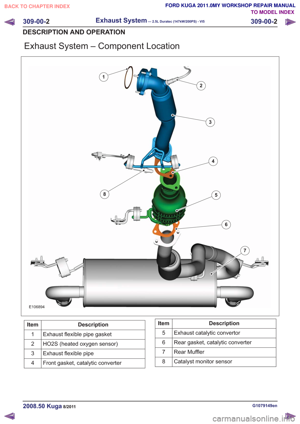
Exhaust System – Component Location
E106894
1
2
3
4
5
6
7
8
Description
Item
Exhaust flexible pipe gasket
1
HO2S (heated oxygen sensor)
2
Exhaust flexible pipe
3
Front gasket, catalytic converter
4Description
Item
Exhaust catalytic convertor
5
Rear gasket, catalytic converter
6
Rear Muffler
7
Catalyst monitor sensor
8
G1079149en2008.50 Kuga8/2011
309-00- 2
Exhaust System— 2.5L Duratec (147kW/200PS) - VI5309-00-
2
DESCRIPTION AND OPERATION
TO MODEL INDEX
BACK TO CHAPTER INDEX
FORD KUGA 2011.0MY WORKSHOP REPAIR MANUAL
Page 1964 of 2057
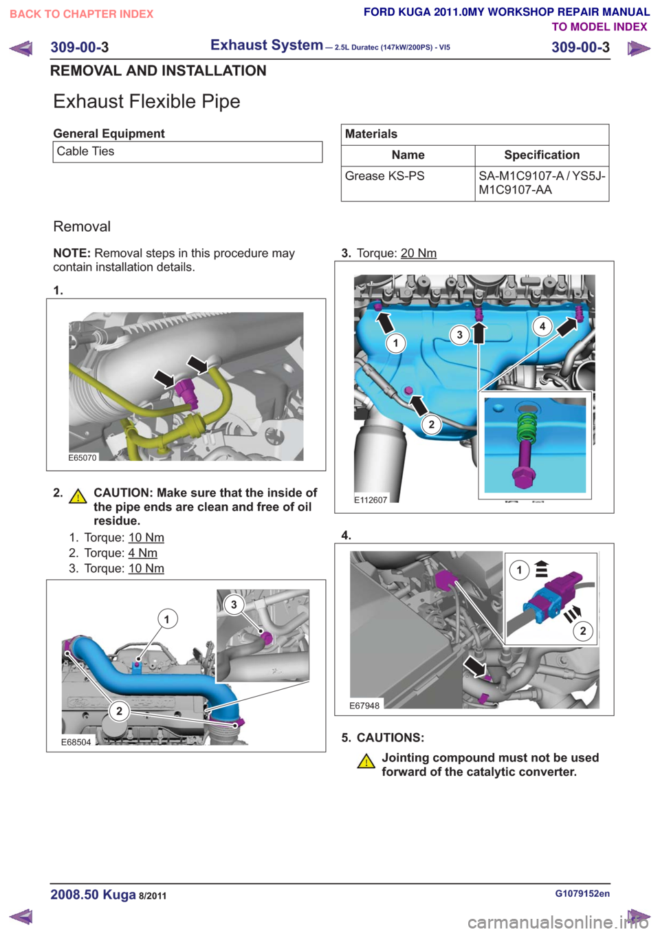
Exhaust Flexible Pipe
General EquipmentCable TiesMaterials
Specification
Name
SA-M1C9107-A / YS5J-
M1C9107-AA
Grease KS-PS
Removal
NOTE:
Removal steps in this procedure may
contain installation details.
1.
E65070
2. CAUTION: Make sure that the inside of the pipe ends are clean and free of oil
residue.
1. Torque: 10Nm
2. Torque: 4Nm
3. Torque: 10Nm
2
1
3
E68504
3.Torque: 20Nm
E112607
1
2
34
4.
E67948
2
1
5. CAUTIONS:
Jointing compound must not be used
forward of the catalytic converter.
G1079152en2008.50 Kuga8/2011
309-00- 3
Exhaust System— 2.5L Duratec (147kW/200PS) - VI5309-00-
3
REMOVAL AND INSTALLATION
TO MODEL INDEX
BACK TO CHAPTER INDEX
FORD KUGA 2011.0MY WORKSHOP REPAIR MANUAL
Page 1965 of 2057
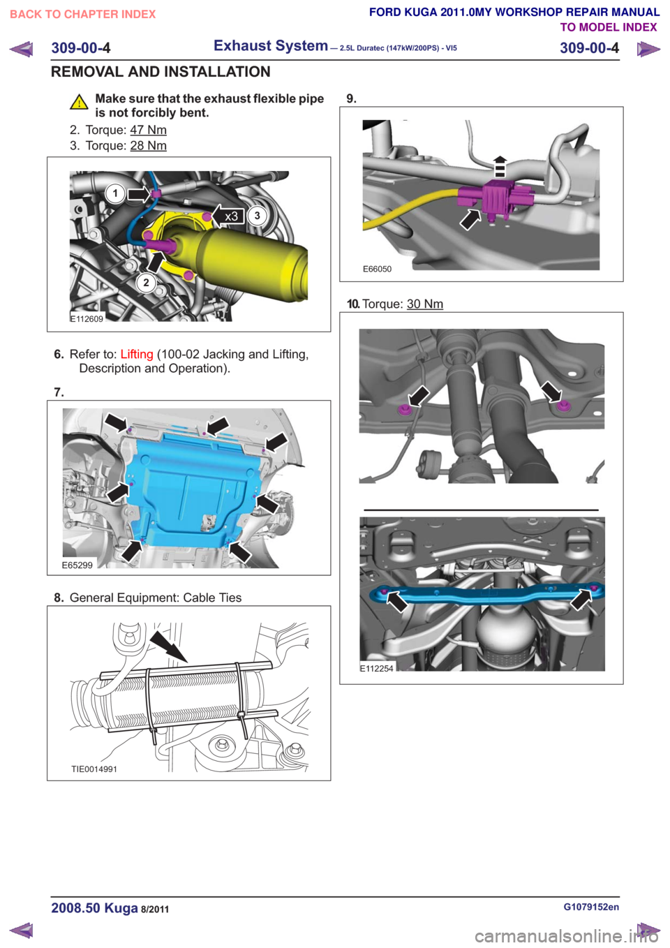
Make sure that the exhaust flexible pipe
is not forcibly bent.
2. Torque: 47
Nm
3. Torque: 28Nm
E112609
x3
1
2
3
6. Refer to: Lifting(100-02 Jacking and Lifting,
Description and Operation).
7.
E65299
8. General Equipment: Cable Ties
TIE0014991
9.
E66050
10.Torque: 30Nm
E112254
G1079152en2008.50 Kuga8/2011
309-00- 4
Exhaust System— 2.5L Duratec (147kW/200PS) - VI5309-00-
4
REMOVAL AND INSTALLATION
TO MODEL INDEX
BACK TO CHAPTER INDEX
FORD KUGA 2011.0MY WORKSHOP REPAIR MANUAL
Page 1966 of 2057
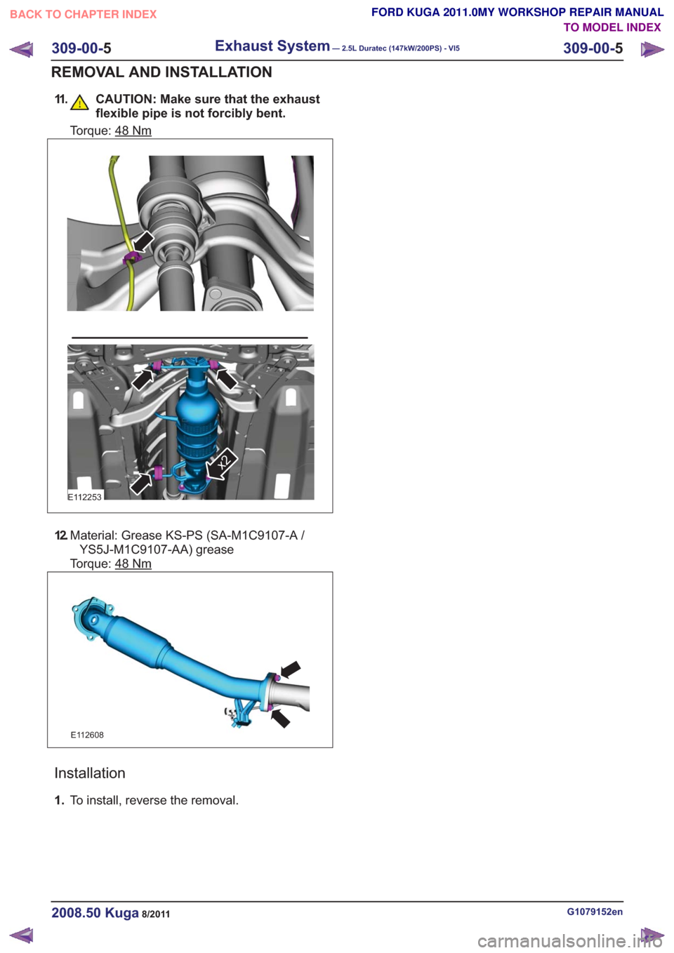
11. CAUTION: Make sure that the exhaustflexible pipe is not forcibly bent.
Torque: 48Nm
E112253
x2
12.Material: Grease KS-PS (SA-M1C9107-A /
YS5J-M1C9107-AA) grease
Torque: 48
Nm
E112608
Installation
1. To install, reverse the removal.
G1079152en2008.50 Kuga8/2011
309-00- 5
Exhaust System— 2.5L Duratec (147kW/200PS) - VI5309-00-
5
REMOVAL AND INSTALLATION
TO MODEL INDEX
BACK TO CHAPTER INDEX
FORD KUGA 2011.0MY WORKSHOP REPAIR MANUAL
Page 1967 of 2057
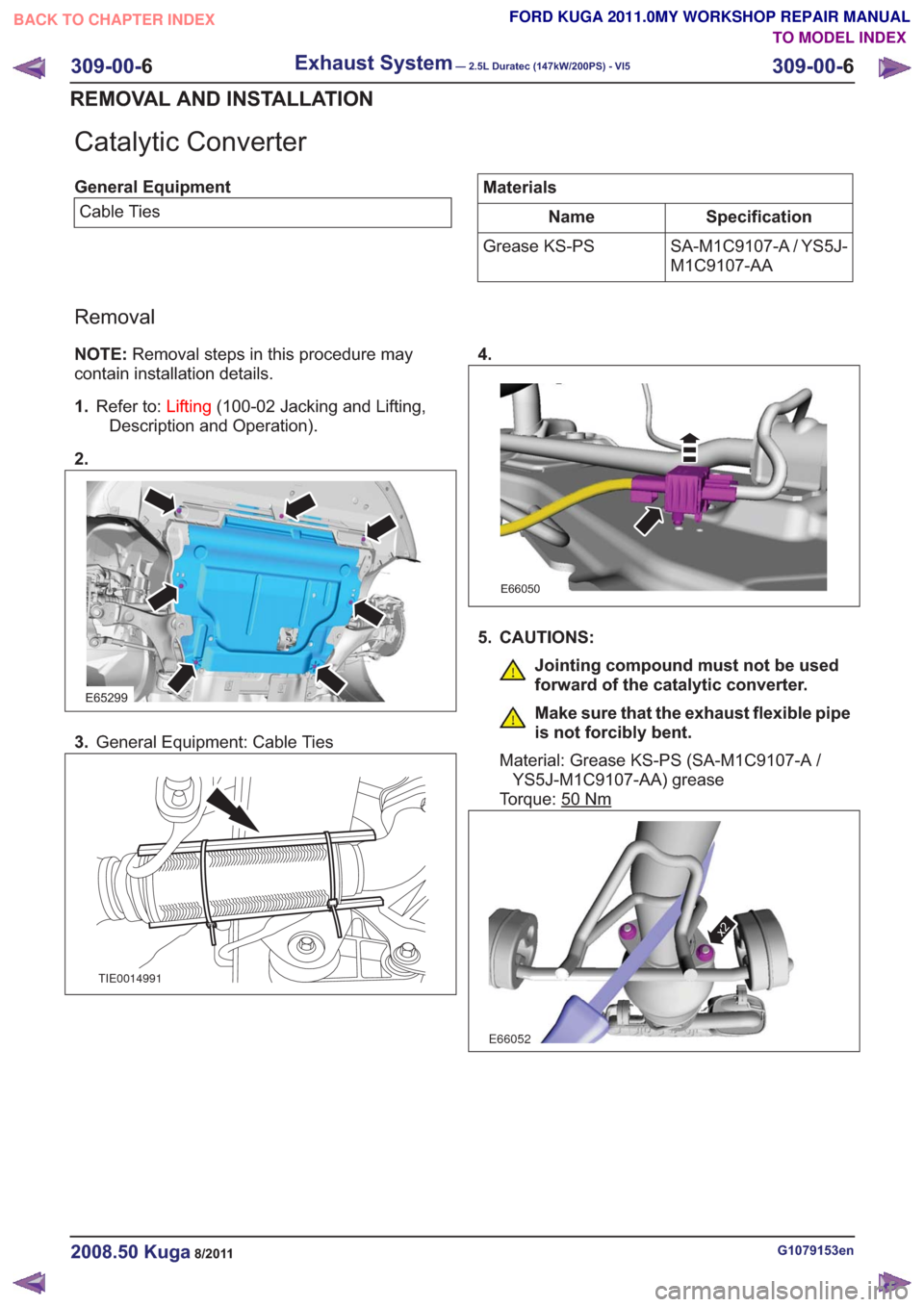
Catalytic Converter
General EquipmentCable TiesMaterials
Specification
Name
SA-M1C9107-A / YS5J-
M1C9107-AA
Grease KS-PS
Removal
NOTE:
Removal steps in this procedure may
contain installation details.
1. Refer to: Lifting(100-02 Jacking and Lifting,
Description and Operation).
2.
E65299
3. General Equipment: Cable Ties
TIE0014991
4.
E66050
5. CAUTIONS:
Jointing compound must not be used
forward of the catalytic converter.
Make sure that the exhaust flexible pipe
is not forcibly bent.
Material: Grease KS-PS (SA-M1C9107-A / YS5J-M1C9107-AA) grease
Torque: 50
Nm
E66052
x2
G1079153en2008.50 Kuga8/2011
309-00- 6
Exhaust System— 2.5L Duratec (147kW/200PS) - VI5309-00-
6
REMOVAL AND INSTALLATION
TO MODEL INDEX
BACK TO CHAPTER INDEX
FORD KUGA 2011.0MY WORKSHOP REPAIR MANUAL
Page 1968 of 2057
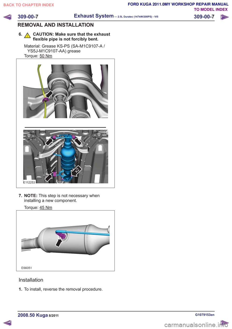
6. CAUTION: Make sure that the exhaustflexible pipe is not forcibly bent.
Material: Grease KS-PS (SA-M1C9107-A /YS5J-M1C9107-AA) grease
Torque: 50
Nm
E112253
x2
7. NOTE: This step is not necessary when
installing a new component.
Torque: 45
Nm
E66051
Installation
1. To install, reverse the removal procedure.
G1079153en2008.50 Kuga8/2011
309-00- 7
Exhaust System— 2.5L Duratec (147kW/200PS) - VI5309-00-
7
REMOVAL AND INSTALLATION
TO MODEL INDEX
BACK TO CHAPTER INDEX
FORD KUGA 2011.0MY WORKSHOP REPAIR MANUAL
Page 1985 of 2057
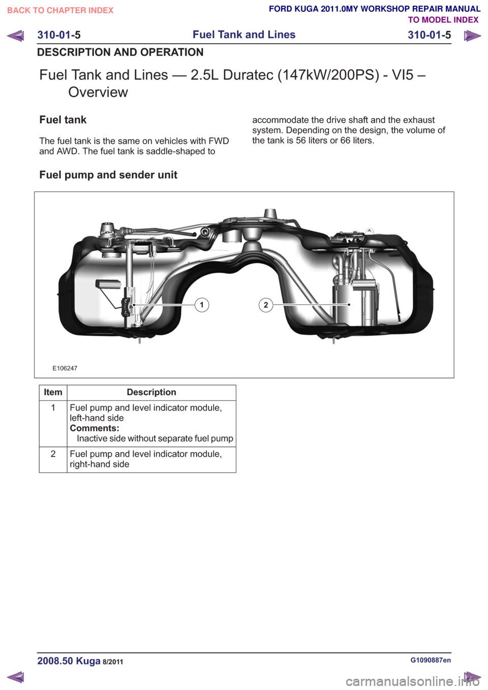
Fuel Tank and Lines — 2.5L Duratec (147kW/200PS) - VI5 –Overview
Fuel tank
The fuel tank is the same on vehicles with FWD
and AWD. The fuel tank is saddle-shaped to accommodate the drive shaft and the exhaust
system. Depending on the design, the volume of
the tank is 56 liters or 66 liters.
Fuel pump and sender unit
E106247
12
Description
Item
Fuel pump and level indicator module,
left-hand side
Comments:Inactive side without separate fuel pump
1
Fuel pump and level indicator module,
right-hand side
2
G1090887en2008.50 Kuga8/2011
310-01-
5
Fuel Tank and Lines
310-01- 5
DESCRIPTION AND OPERATION
TO MODEL INDEX
BACK TO CHAPTER INDEX
FORD KUGA 2011.0MY WORKSHOP REPAIR MANUAL
