Engine control FORD KUGA 2011 1.G Owner's Manual
[x] Cancel search | Manufacturer: FORD, Model Year: 2011, Model line: KUGA, Model: FORD KUGA 2011 1.GPages: 2057
Page 388 of 2057
Module Configuration
Activation
1.
Install the most up-to-date software version in
the integrated diagnostic system (IDS).
2. In IDS, select the "Module reprogramming"
submenu in the "Module programming" menu
tool box and then follow the instructions.
3. Transfer a new software version (if available)
to the powertrain control module (PCM) using
IDS, if a module-reprogramming of the PCM
may be required in the case of engine running
concerns.
4. Following installation of a wheel/tire
combination, for which the tire-tread
circumference does not correspond to that of
standard tires, the tire size must be changed in
the PCM using IDS. Therefore select the
"Programmable parameters" submenu and enter
the corresponding tire size under the "tire size"
menu item. G1158256en
2008.50 Kuga 8/2011 418-01-2
Module Configuration
418-01-2
GENERAL PROCEDURESTO MODEL INDEX
BACK TO CHAPTER INDEX
FORD KUGA 2011.0MY WORKSHOP REPAIR MANUAL
Page 448 of 2057
Description
Item
Passive key (radio remote control with
integrated emergency key)Refer to Component Description: (page
?)
4
RF receiverRefer to Component Description: (page
?)
5
PCM6 Description
Item
Transceiver of passive anti-theft system
(emergency start function)Refer to Component Description: (page
?)
7
Instrument clusterRefer to Component Description: (page
?)
8
System Operation
Passive Anti-theft System
The passive anti-theft system PATS (passive
anti-theft system) is based on an electronic engine
immobiliser.
The driver does not need to intervene in any way
to protect the vehicle, since PATS is automatically
activated when the ignition is switched off.
Component Description
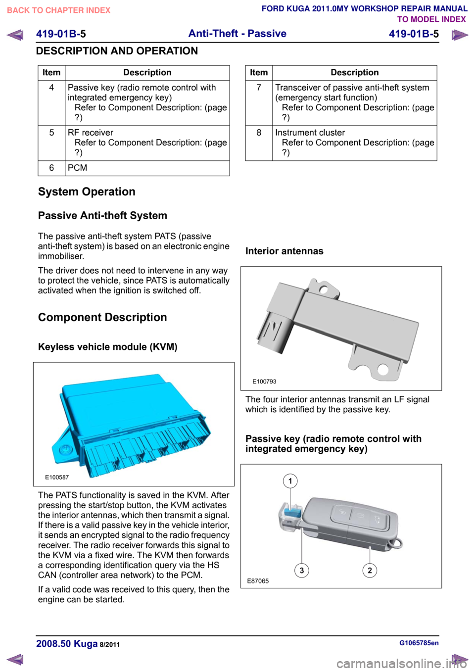
Keyless vehicle module (KVM) The PATS functionality is saved in the KVM. After
pressing the start/stop button, the KVM activates
the interior antennas, which then transmit a signal.
If there is a valid passive key in the vehicle interior,
it sends an encrypted signal to the radio frequency
receiver. The radio receiver forwards this signal to
the KVM via a fixed wire. The KVM then forwards
a corresponding identification query via the HS
CAN (controller area network) to the PCM.
If a valid code was received to this query, then the
engine can be started. Interior antennas
The four interior antennas transmit an LF signal
which is identified by the passive key.
Passive key (radio remote control with
integrated emergency key)
G1065785en
2008.50 Kuga 8/2011 419-01B-5
Anti-Theft - Passive
419-01B-5
DESCRIPTION AND OPERATIONTO MODEL INDEX
BACK TO CHAPTER INDEX
FORD KUGA 2011.0MY WORKSHOP REPAIR MANUALE100587 E100793 E87065132
Page 456 of 2057

Description
Item
HS CAN
1
DLC2
MS CAN
3
Instrument cluster (gateway)
4
Front windshield wiper motors
5
GEM6
Rear window wiper motors
7
Indicator/heated windshield
8
Indicator/heated rear window
9 Description
Item
Mini-liftgate latch motor
10
Liftgate latch motor
11
Electric booster Heater
12
Front wiper windscreen washer pump
13
Rear wiper windscreen washer pump
14
Headlamp
15
Courtesy Lighting
16
Alarm horn
17
System Operation
GEM.
The following functions are controlled or performed
by the GEM at a battery voltage of between 9 and
16 volts:
• Current distribution
• Battery charging (Smart Charge)
• Ignition overload protection
• Headlamp switch-off delay
• Turn signals
• Interior lighting
• Heated windscreen
• Heated rear window and heated external mirrors
• Ambient air temperature
• Brake fluid level
• Automatic headlamps
• Combined rain sensor/light sensor
• Windshield wash/wipe system
• Speed control – reads the speed control switches andtransmits signals on the CAN data bus
• central door locking – transmits signals on the CAN data bus
• Anti-theft
• Electric booster Heater
• Climate control
• Parking brake –(monitors the switch and transmits the signal
on the CAN data bus
• Communication via the medium-speed CAN data bus Component Description
Battery charging (Smart Charge)
In addition to the familiar functions, the Smart
Charge system also performs the following
functions:
•
Automatic deactivation of non-critical high power
electrical consumers when the battery voltage
is low in order to reduce the level of current
drawn.
• Automatic activation of non-critical high power electrical consumers when the battery voltage
is excessively high in order to protect
components which are sensitive to increased
voltages.
The battery charging current is optimized through
continuous calculation of the battery temperature
and monitoring of the alternator output voltage.
The alternator load is signaled to the PCM
(powertrain control module) in order to provide it
with an early indication when an electric component
is to be switched on or off, thereby also providing
information about imminent changes to the amount
of torque demanded by the alternator. By
evaluating this information the PCM is capable of
increasing the stability of the engine under idling.
The two remaining functions of the Smart Charge
system are controlled by the GEM. G1030788en
2008.50 Kuga 8/2011 419-10-6
Multifunction Electronic Modules
419-10-6
DESCRIPTION AND OPERATIONTO MODEL INDEX
BACK TO CHAPTER INDEX
FORD KUGA 2011.0MY WORKSHOP REPAIR MANUAL
Page 1251 of 2057
Rear Drive Axle and Differential – System Operation andComponent Description
System Operation
General Information
The powertrain with all-wheel drive consists of the
following main components:
• engine
• transaxle with front axle differential
• transfer box
• halfshafts and driveshafts
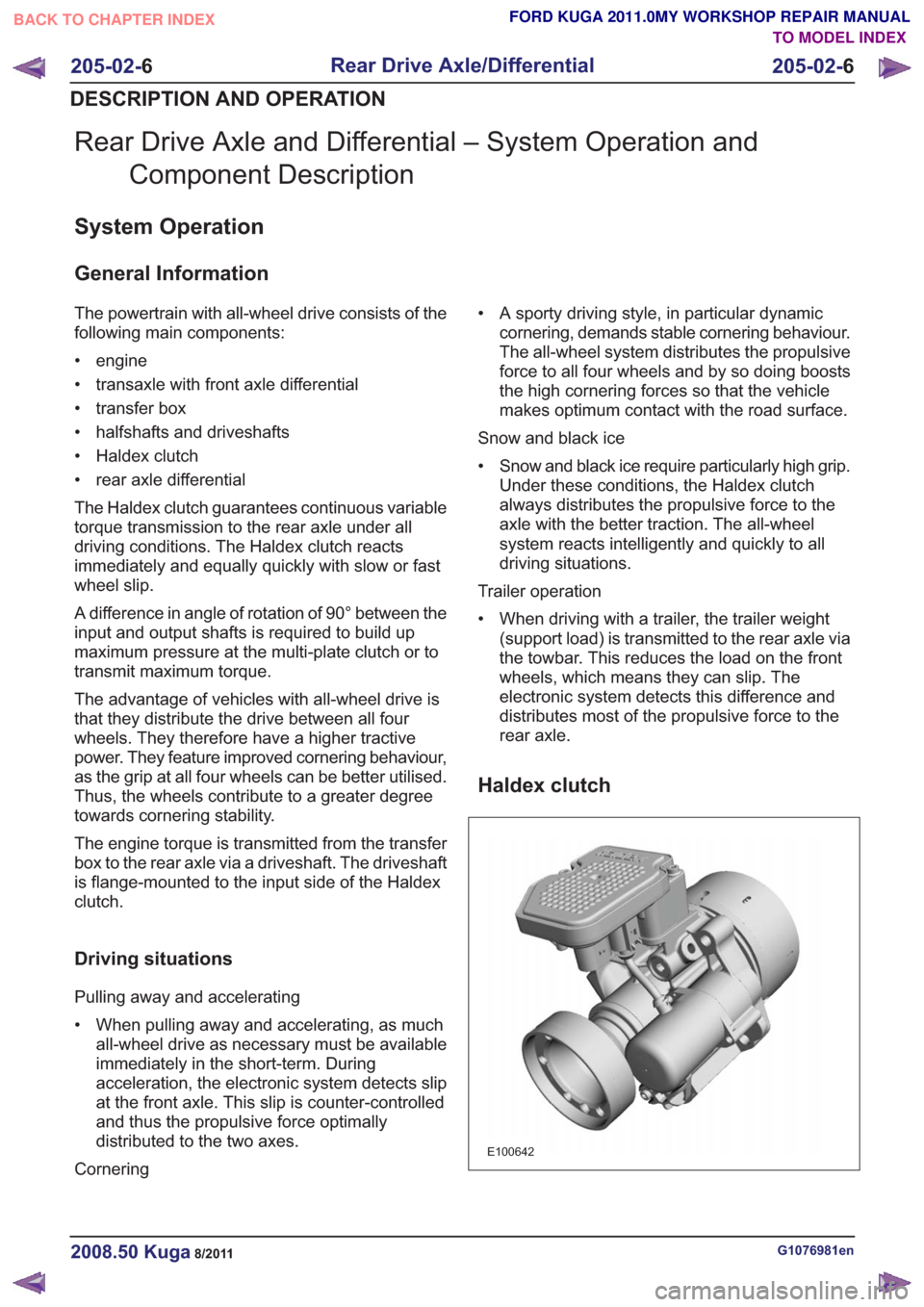
• Haldex clutch
• rear axle differential
The Haldex clutch guarantees continuous variable
torque transmission to the rear axle under all
driving conditions. The Haldex clutch reacts
immediately and equally quickly with slow or fast
wheel slip.
A difference in angle of rotation of 90° between the
input and output shafts is required to build up
maximum pressure at the multi-plate clutch or to
transmit maximum torque.
The advantage of vehicles with all-wheel drive is
that they distribute the drive between all four
wheels. They therefore have a higher tractive
power. They feature improved cornering behaviour,
as the grip at all four wheels can be better utilised.
Thus, the wheels contribute to a greater degree
towards cornering stability.
The engine torque is transmitted from the transfer
box to the rear axle via a driveshaft. The driveshaft
is flange-mounted to the input side of the Haldex
clutch.
Driving situations
Pulling away and accelerating
• When pulling away and accelerating, as muchall-wheel drive as necessary must be available
immediately in the short-term. During
acceleration, the electronic system detects slip
at the front axle. This slip is counter-controlled
and thus the propulsive force optimally
distributed to the two axes.
Cornering • A sporty driving style, in particular dynamic
cornering, demands stable cornering behaviour.
The all-wheel system distributes the propulsive
force to all four wheels and by so doing boosts
the high cornering forces so that the vehicle
makes optimum contact with the road surface.
Snow and black ice
• Snow and black ice require particularly high grip. Under these conditions, the Haldex clutch
always distributes the propulsive force to the
axle with the better traction. The all-wheel
system reacts intelligently and quickly to all
driving situations.
Trailer operation
• When driving with a trailer, the trailer weight (support load) is transmitted to the rear axle via
the towbar. This reduces the load on the front
wheels, which means they can slip. The
electronic system detects this difference and
distributes most of the propulsive force to the
rear axle.
Haldex clutch
E100642
G1076981en2008.50 Kuga8/2011
205-02- 6
Rear Drive Axle/Differential
205-02- 6
DESCRIPTION AND OPERATION
TO MODEL INDEX
BACK TO CHAPTER INDEX
FORD KUGA 2011.0MY WORKSHOP REPAIR MANUAL
Page 1255 of 2057
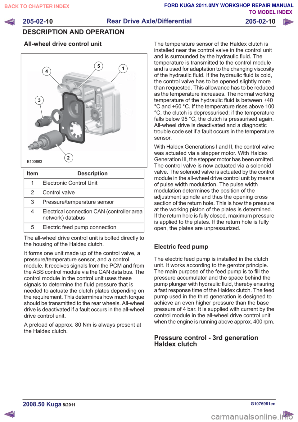
All-wheel drive control unit
E100663
14
3
2
5
Description
Item
Electronic Control Unit
1
Control valve
2
Pressure/temperature sensor
3
Electrical connection CAN (controller area
network) databus
4
Electric feed pump connection
5
The all-wheel drive control unit is bolted directly to
the housing of the Haldex clutch.
It forms one unit made up of the control valve, a
pressure/temperature sensor, and a control
module. It receives signals from the PCM and from
the ABS control module via the CAN data bus. The
control module in the control unit uses these
signals to determine the fluid pressure that is
needed to actuate the clutch plates depending on
the requirement. This determines how much torque
should be transmitted to the rear wheels. All-wheel
drive is deactivated if a fault occurs in the all-wheel
drive control unit.
A preload of approx. 80 Nm is always present at
the Haldex clutch. The temperature sensor of the Haldex clutch is
installed near the control valve in the control unit
and is surrounded by the hydraulic fluid. The
temperature is transmitted to the control module
and is used for adaptation to the changing viscosity
of the hydraulic fluid. If the hydraulic fluid is cold,
the control valve has to be opened slightly more
than requested. This allowance has to be reduced
as the temperature increases. The normal working
temperature of the hydraulic fluid is between +40
°C and +60 °C. If the temperature rises above 100
°C, the clutch is depressurised; if the temperature
falls below 95 °C, the clutch is pressurised again.
All-wheel drive is deactivated and a diagnostic
trouble code set if a fault occurs in the temperature
sensor.
With Haldex Generations I and II, the control valve
was actuated via a stepper motor. With Haldex
Generation III, the stepper motor has been omitted.
The control valve is now actuated via a solenoid
valve. The solenoid valve is actuated by the control
module in the all-wheel drive control unit by means
of pulse width modulation. The pulse width
modulation determines the position of the
adjustment spindle and thus the opening cross
section of the return hole. This is how the pressure
at the working piston of the plates is determined.
If the return hole is fully closed, maximum pressure
is applied to the plates. If the return hole is fully
open, the plates are unpressurized.
Electric feed pump
The electric feed pump is installed in the clutch
unit. It works according to the gerotor principle.
The main purpose of the feed pump is to fill the
pressure accumulator and the space behind the
pump plunger with hydraulic fluid, thereby ensuring
a fast response time of the Haldex clutch. The feed
pump used in the third generation is designed to
achieve an even higher pressure than the base
pressure of 4 bar. It is supplied with current by the
control module in the all-wheel drive control unit
when the engine is running above approx. 400 rpm.
Pressure control - 3rd generation
Haldex clutch
G1076981en2008.50 Kuga8/2011
205-02-
10
Rear Drive Axle/Differential
205-02- 10
DESCRIPTION AND OPERATION
TO MODEL INDEX
BACK TO CHAPTER INDEX
FORD KUGA 2011.0MY WORKSHOP REPAIR MANUAL
Page 1261 of 2057
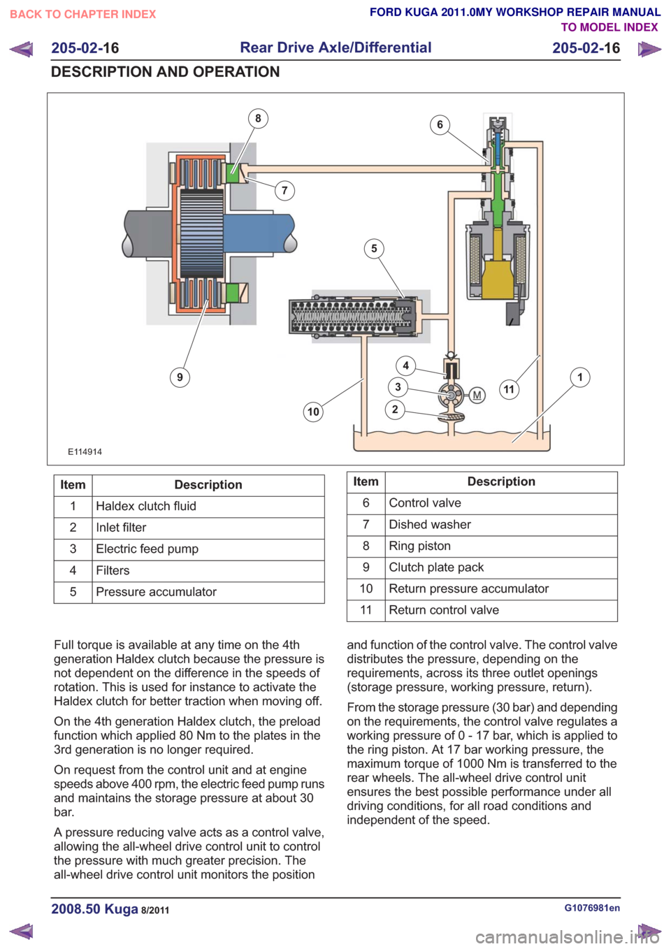
6
7
8
9
10
11
1
2
3
4
5
6
7
8
9
10
11
E114914
Description
Item
Haldex clutch fluid
1
Inlet filter
2
Electric feed pump
3
Filters4
Pressure accumulator
5Description
Item
Control valve
6
Dished washer
7
Ring piston
8
Clutch plate pack
9
Return pressure accumulator
10
Return control valve
11
Full torque is available at any time on the 4th
generation Haldex clutch because the pressure is
not dependent on the difference in the speeds of
rotation. This is used for instance to activate the
Haldex clutch for better traction when moving off.
On the 4th generation Haldex clutch, the preload
function which applied 80 Nm to the plates in the
3rd generation is no longer required.
On request from the control unit and at engine
speeds above 400 rpm, the electric feed pump runs
and maintains the storage pressure at about 30
bar.
A pressure reducing valve acts as a control valve,
allowing the all-wheel drive control unit to control
the pressure with much greater precision. The
all-wheel drive control unit monitors the position and function of the control valve. The control valve
distributes the pressure, depending on the
requirements, across its three outlet openings
(storage pressure, working pressure, return).
From the storage pressure (30 bar) and depending
on the requirements, the control valve regulates a
working pressure of 0 - 17 bar, which is applied to
the ring piston. At 17 bar working pressure, the
maximum torque of 1000 Nm is transferred to the
rear wheels. The all-wheel drive control unit
ensures the best possible performance under all
driving conditions, for all road conditions and
independent of the speed.
G1076981en2008.50 Kuga8/2011
205-02-
16
Rear Drive Axle/Differential
205-02- 16
DESCRIPTION AND OPERATION
TO MODEL INDEX
BACK TO CHAPTER INDEX
FORD KUGA 2011.0MY WORKSHOP REPAIR MANUAL
Page 1354 of 2057
4. Remove the vacuum hose from the brakebooster. Manifold vacuum should be available
at the brake booster end of the hose with the
engine at idle speed and the transaxle in the
NEUTRAL position. Make sure that all unused
vacuum outlets are correctly capped, hose
connectors are correctly secured and vacuum
hoses are in good condition. When it is
established that manifold vacuum is available
to the brake booster, connect the vacuum hose
to the brake booster and repeat Step 3. If no
downward movement of the brake pedal is felt,
install a new brake booster.
5. Operate the engine a minimum of 10 seconds at approximately 1200 rpm. Stop the engine and
let the vehicle stand for 10 minutes. Then, apply
the brake pedal with approximately 89 N (20 lb)
force. The pedal feel (brake application) should
be the same as that noted with the engine
operating. If the brake pedal feels hard (no
power assist), install a new vacuum check valve
and then repeat the test. If the brake pedal still
feels hard, install a new brake booster. If the
brake pedal movement feels spongy, bleed the
brake system. REFER to: (206-00 Brake System
- General Information)
Brake System Bleeding (General Procedures),
Brake System Pressure Bleeding (General
Procedures),
Component Bleeding (General Procedures).
Brake Master Cylinder
Usually, the first and strongest indicator of anything
wrong with the braking system is a feeling through
the brake pedal. In diagnosing the condition of the
brake master cylinder, check pedal feel as
evidence of a brake concern. Check for the red
brake warning indicator illumination and the fluid
level in the master cylinder reservoir.
Normal Conditions
The following conditions are considered normal
and are not indications that the brake master
cylinder is in need of service.
– Modern brake systems are not designed to
produce as hard a pedal effort as in the past.
Complaints of light pedal efforts should be compared to pedal efforts of another vehicle, of
the same model and year.
– During normal operation of the brake pedal, the fluid level in the reservoir will rise during brake
pedal application and fall during release. The
net fluid level (i.e., after brake pedal application
and release) will remain unchanged.
– A trace of brake fluid will exists on the brake booster shell below the master cylinder
mounting flange. This results from the normal
lubricating action of the master cylinder bore
end seal.
– The fluid level will fall with brake shoe and lining wear.
Abnormal Conditions
NOTE: Prior to performing any diagnosis, make
sure the brake system warning indicator is
functional.
Changes in brake pedal feel or travel are indicators
that something could be wrong with the braking
system. The diagnostic procedure and techniques
use brake pedal feel, warning indicator illumination
and low brake fluid level as indicators in diagnosing
braking system concerns. The following conditions
are considered abnormal and indicate that the
brake master cylinder is in need of service.
– The brake pedal goes down fast. This could be caused by an external or internal leak.
– The brake pedal eases down slowly. This could be caused by an external or internal leak.
– The brake pedal is low and or feels spongy. This condition may be caused by no fluid in the brake
master cylinder reservoir, reservoir cap vent
holes clogged or air in the hydraulic system.
– The brake pedal effort is excessive. This may be caused by a bind or obstruction in the pedal
or linkage, clogged fluid control valve or
insufficient booster vacuum.
– The rear brakes lock up during light pedal force. This may be caused by incorrect tire pressures,
grease or fluid on the brake shoes and linings,
damaged brake shoes and linings, incorrectly
adjusted parking brake, or damaged or
contaminated brake pressure control valves.
– The brake pedal effort is erratic. This condition could be caused by a brake booster malfunction,
extreme caliper piston knock back or incorrectly
installed brake shoes and linings.
– The red brake warning indicator is ON. This may be caused by low fluid level, ignition wire routing
G1058975en2008.50 Kuga8/2011
206-00- 18
Brake System - General Information
206-00- 18
DIAGNOSIS AND TESTING
TO MODEL INDEX
BACK TO CHAPTER INDEX
FORD KUGA 2011.0MY WORKSHOP REPAIR MANUAL
Page 1425 of 2057
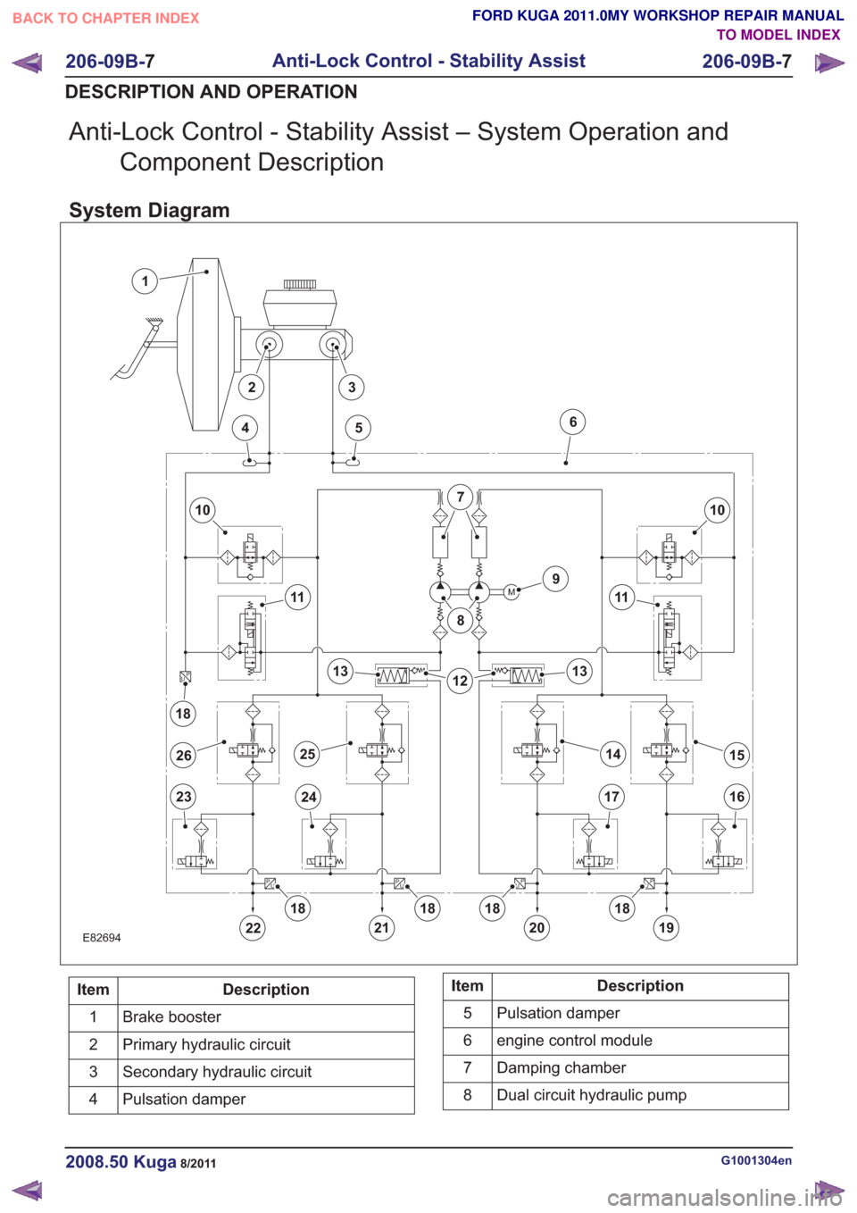
Anti-Lock Control - Stability Assist – System Operation andComponent Description
System Diagram
E82694
M
P
UP
U
P
U
P
U
P
U
1
10
22
23
456
7
8
9
11
1213
1415
1617
18
2324
13
11
10
19
2526
2120
181818
18
Description
Item
Brake booster
1
Primary hydraulic circuit
2
Secondary hydraulic circuit
3
Pulsation damper
4Description
Item
Pulsation damper
5
engine control module
6
Damping chamber
7
Dual circuit hydraulic pump
8
G1001304en2008.50 Kuga8/2011
206-09B- 7
Anti-Lock Control - Stability Assist
206-09B- 7
DESCRIPTION AND OPERATION
TO MODEL INDEX
BACK TO CHAPTER INDEX
FORD KUGA 2011.0MY WORKSHOP REPAIR MANUAL
Page 1428 of 2057
Description
Item
Battery
1
Battery junction box (BJB) in the engine
compartment
2
Generic electronic module (GEM)
3
Powertrain Control Module (PCM)
4
Instrument cluster
5
Data link connector (DLC)
6
Steering Wheel Rotation Sensor
7
ABS/ESP module or hydraulic control unit
(HCU)
8Description
Item
Combined yaw rate sensor and lateral
acceleration sensor / longitudinal
acceleration sensor
9
Front wheel sensor
10
Rear wheel sensor
11
Rear wheel sensor
12
Front wheel sensor
13
ESP switch
14
Rear brakes
15
Front brake
16
The ABS monitors the different wheel speeds of
the vehicle with the aid of wheel speed sensors.
Using the data from all of the wheel speed sensors,
the ABS module calculates the so-called reference
speed, which is a measure of the actual road
speed. The ABS module compares the individual
circumferential wheel speeds with this reference
speed when the driver initiates braking. If one or
more of the circumferential wheel speeds deviates
too far from the reference speed, this means that
slip at the affected wheels is so great that steering
stability of the vehicle is no longer ensured. The
ABS module actuates electro-mechanical valves
which influence the brake pressure at the relevant
wheels.
Like the traction control system (TCS), the ESP
system uses a large proportion of the ABS
components. In addition, there are sensors which
pick up the steering angle, the acceleration forces
acting on the vehicle and the yaw rate or yaw
moment. The sensors transmit these signals to the
combined ABS/ESP module. Using the wheel
speed and steering angle data, the ABS/ESP
module calculates the direction of travel planned
by the driver and determines the corresponding
speed-dependent lateral acceleration and yaw
moment. These values are compared with those
actual measured. If the actual lateral acceleration
and the yaw moment deviate excessively from the
target values (unstable driving characteristics), the
ABS/ESP module actuates individual brakes
selectively via the HCU (hydraulic control unit). In
addition, the engine speed is reduced by
intervention in the engine management system.
How the system works for understeer: In the
event of understeer, brake intervention occurs at
the wheels on the inside of the curve. The rear
wheel is braked heavily, so that a high amount of slip is caused. In this way, the cornering force of
the rear axle is heavily reduced and the centrifugal
force that now becomes effective turns the rear of
the vehicle back into the curve. The front wheel is
not braked as hard. The braking force that is
transmitted via the front wheel to the road surface
generates a torque with the aid of the lever arm
(vertical tire force to the vehicle's centre of gravity),
which supports the yaw moment of the vehicle.
Both measures together result in the vehicle
reverting back to the curved path intended by the
driver.
How the system works for oversteer:
In the
event of oversteer the wheels on the outside of the
curve are braked. This time, the front wheel is
subjected to a high level of slip so that the
cornering force at the front axle is reduced. The
rear wheel is not braked as heavily and, together
with the effective lever arm, results in a reduction
in the vehicle yaw moment. Both measures
together result in the vehicle being stabilized and
reverting back to the curved path intended by the
driver.
If ESP control occurs, possible ABS interventions
will be overridden as the ESP works at higher slip
rates than the ABS.
Emergency brake assist (EBA): The emergency
brake assist helps drivers in emergency braking
situations by automatically applying the brakes with
the maximum possible braking force.
If the brake pedal is pressed very suddenly, the
ABS module increases the hydraulic pressure to
all of the brakes until the threshold for ABS
intervention is reached. This applies the maximum
braking effort for the available traction. The ABS
control unit monitors inputs from the brake pedal
switch and from the pressure sensor within the
G1001304en2008.50 Kuga8/2011
206-09B- 10
Anti-Lock Control - Stability Assist
206-09B- 10
DESCRIPTION AND OPERATION
TO MODEL INDEX
BACK TO CHAPTER INDEX
FORD KUGA 2011.0MY WORKSHOP REPAIR MANUAL
Page 1429 of 2057
HCU to check for sudden actuation of the brakes.
With the brake pedal pressed, the ABS module
triggers emergency braking if the rate of increase
of hydraulic pressure exceeds the predetermined
limit.
If the brake pedal is pressed so hard that the ABS
becomes active on the front wheels then the ABS
control unit increases the pressure to the rear
wheel brakes up to the ABS intervention threshold.
EBA operation continues until the driver releases
the brake pedal sufficiently for the hydraulic
pressure in the HCU to drop below a threshold
value stored in the ABS module.
Trailer stability control:If the vehicle is ordered
with a trailer coupling then the Trailer Stability
Control function is integrated in the ESP. The ESP
detects snaking when driving with a trailer and
reduces the speed of the vehicle and trailer through
adapted braking and, if necessary, by also reducing
the engine output until the snaking movement of
the trailer is corrected.
Roll-over protection: The ESP dynamically
determines the tipping tendency of the vehicle and
works in conjunction with the EBA system to
prevent the vehicle from tipping over during
dynamic maneuvers like lane changing or while
negotiating bends.
Emergency brake light: The emergency brake
light automatically switches on the hazard flasher
system to warn drivers of other vehicles that
emergency braking is being initiated. Based on a
defined delay value, the ABS/ESP module sends
a signal to the generic electronic module (GEM)
via the CAN data bus. The GEM activates the
hazard flasher system, that then flashes 7 times.
Prerequisites for activation of the emergency brake
light are:
• The speed is higher than 50 km/h.
• The brake pedal is being actuated.
• The deceleration is greater than 9 m/s².
To prevent activation on snow or ice, for example,
the following prerequisites must be met:
• The speed is higher than 50 km/h.
• The brake pedal is being actuated.
• ABS regulation takes place.
• The deceleration is greater than 6 m/s².
Tire pressure monitoring system: The tire
pressure monitoring system used in the Kuga is
able to detect loss of air in a tire at an early stage
and warn the driver. Because it can only compare
the behaviour of the tyres with each other, it is not possible to draw conclusions about the absolute
tyre pressure. It is also not possible to monitor the
spare tyre pressure. In order for the system to
operate correctly, the tyre pressures must be
regularly checked and corrected and the system
subsequently initialised (see below).
The tire pressure monitoring system used here,
depending on the equipment level, is built into the
anti-lock braking system (ABS) as an extra function
and therefore does not have its own sensors.
The ABS module measures the loss of pressure
in the tyres by calculation using the wheel speed
sensors of the ABS system. If a tyre loses
pressure, its diameter decreases and the speed of
the wheel therefore increases. If the ABS module
detects such a loss in pressure, it sends a signal
to the instrument cluster via the CAN bus and a
warning message is displayed in the message
centre. The warning threshold depends among
other things on the dimension of the tyres being
used, the vehicle operating conditions and the
status at the last initialisation. Since neither the
absolute tyre pressure nor the position of the tyre
is known, the pressure of all the tyres must be
checked and the system re-initialised after a tyre
pressure warning. If necessary, the cause of the
loss of pressure must be investigated.
Regular tyre pressure checks are still necessary.
The system must be initialised after a tyre is
changed, winter or summer tyres fitted, the
pressures corrected or adjusted to suit the vehicle
load. This can be done by the driver using the
driver information system. For further information,
see: Owner’s Manual.
Component Description
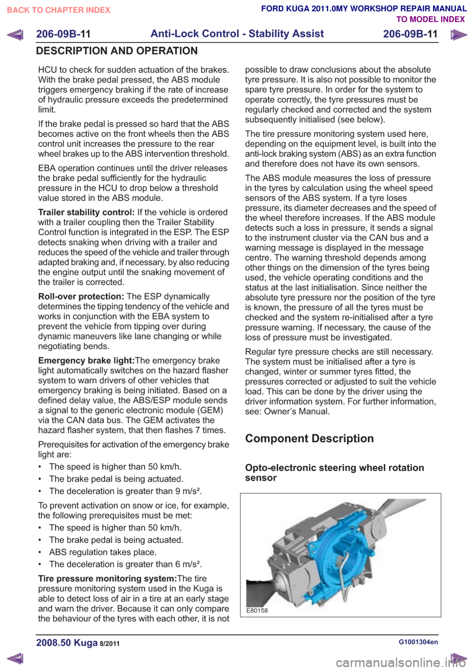
Opto-electronic steering wheel rotation
sensor
E80158
G1001304en2008.50 Kuga8/2011
206-09B-
11
Anti-Lock Control - Stability Assist
206-09B- 11
DESCRIPTION AND OPERATION
TO MODEL INDEX
BACK TO CHAPTER INDEX
FORD KUGA 2011.0MY WORKSHOP REPAIR MANUAL