junction box FORD KUGA 2011 1.G Owner's Manual
[x] Cancel search | Manufacturer: FORD, Model Year: 2011, Model line: KUGA, Model: FORD KUGA 2011 1.GPages: 2057
Page 1428 of 2057
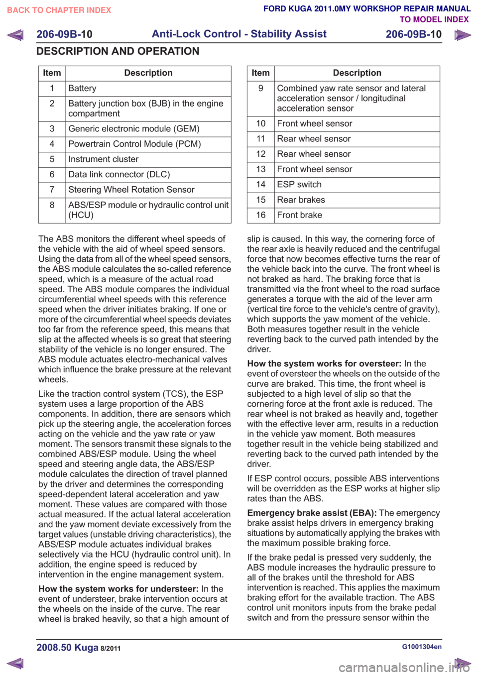
Description
Item
Battery
1
Battery junction box (BJB) in the engine
compartment
2
Generic electronic module (GEM)
3
Powertrain Control Module (PCM)
4
Instrument cluster
5
Data link connector (DLC)
6
Steering Wheel Rotation Sensor
7
ABS/ESP module or hydraulic control unit
(HCU)
8Description
Item
Combined yaw rate sensor and lateral
acceleration sensor / longitudinal
acceleration sensor
9
Front wheel sensor
10
Rear wheel sensor
11
Rear wheel sensor
12
Front wheel sensor
13
ESP switch
14
Rear brakes
15
Front brake
16
The ABS monitors the different wheel speeds of
the vehicle with the aid of wheel speed sensors.
Using the data from all of the wheel speed sensors,
the ABS module calculates the so-called reference
speed, which is a measure of the actual road
speed. The ABS module compares the individual
circumferential wheel speeds with this reference
speed when the driver initiates braking. If one or
more of the circumferential wheel speeds deviates
too far from the reference speed, this means that
slip at the affected wheels is so great that steering
stability of the vehicle is no longer ensured. The
ABS module actuates electro-mechanical valves
which influence the brake pressure at the relevant
wheels.
Like the traction control system (TCS), the ESP
system uses a large proportion of the ABS
components. In addition, there are sensors which
pick up the steering angle, the acceleration forces
acting on the vehicle and the yaw rate or yaw
moment. The sensors transmit these signals to the
combined ABS/ESP module. Using the wheel
speed and steering angle data, the ABS/ESP
module calculates the direction of travel planned
by the driver and determines the corresponding
speed-dependent lateral acceleration and yaw
moment. These values are compared with those
actual measured. If the actual lateral acceleration
and the yaw moment deviate excessively from the
target values (unstable driving characteristics), the
ABS/ESP module actuates individual brakes
selectively via the HCU (hydraulic control unit). In
addition, the engine speed is reduced by
intervention in the engine management system.
How the system works for understeer: In the
event of understeer, brake intervention occurs at
the wheels on the inside of the curve. The rear
wheel is braked heavily, so that a high amount of slip is caused. In this way, the cornering force of
the rear axle is heavily reduced and the centrifugal
force that now becomes effective turns the rear of
the vehicle back into the curve. The front wheel is
not braked as hard. The braking force that is
transmitted via the front wheel to the road surface
generates a torque with the aid of the lever arm
(vertical tire force to the vehicle's centre of gravity),
which supports the yaw moment of the vehicle.
Both measures together result in the vehicle
reverting back to the curved path intended by the
driver.
How the system works for oversteer:
In the
event of oversteer the wheels on the outside of the
curve are braked. This time, the front wheel is
subjected to a high level of slip so that the
cornering force at the front axle is reduced. The
rear wheel is not braked as heavily and, together
with the effective lever arm, results in a reduction
in the vehicle yaw moment. Both measures
together result in the vehicle being stabilized and
reverting back to the curved path intended by the
driver.
If ESP control occurs, possible ABS interventions
will be overridden as the ESP works at higher slip
rates than the ABS.
Emergency brake assist (EBA): The emergency
brake assist helps drivers in emergency braking
situations by automatically applying the brakes with
the maximum possible braking force.
If the brake pedal is pressed very suddenly, the
ABS module increases the hydraulic pressure to
all of the brakes until the threshold for ABS
intervention is reached. This applies the maximum
braking effort for the available traction. The ABS
control unit monitors inputs from the brake pedal
switch and from the pressure sensor within the
G1001304en2008.50 Kuga8/2011
206-09B- 10
Anti-Lock Control - Stability Assist
206-09B- 10
DESCRIPTION AND OPERATION
TO MODEL INDEX
BACK TO CHAPTER INDEX
FORD KUGA 2011.0MY WORKSHOP REPAIR MANUAL
Page 1465 of 2057
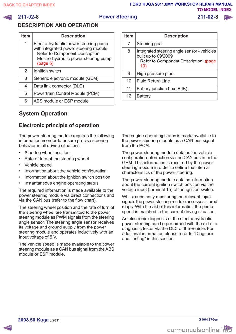
Description
Item
Electro-hydraulic power steering pump
with integrated power steering moduleRefer to Component Description:
Electro-hydraulic power steering pump
(page5)
1
Ignition switch
2
Generic electronic module (GEM)
3
Data link connector (DLC)
4
Powertrain Control Module (PCM)
5
ABS module or ESP module
6Description
Item
Steering gear
7
Integrated steering angle sensor - vehicles
built up to 09/2009RefertoComponentDescription:(page
10)
8
High pressure pipe
9
Fluid Return Line
10
Battery junction box (BJB)
11
Battery
12
System Operation
Electronic principle of operation
The power steering module requires the following
information in order to ensure precise steering
behavior in all driving situations:
• Steering wheel position
• Rate of turn of the steering wheel
• Vehicle speed
• Information about the vehicle configuration
• Information about the ignition switch position
• Instantaneous engine operating status
The required information is made available to the
power steering module via direct connections and
via the CAN bus (refer to the flow chart).
The steering wheel position and the rate of turn of
the steering wheel are transmitted to the power
steering module as PWM signals from the steering
angle sensor. The steering angle sensor receives
its voltage and ground supply from the power
steering module and operates inductively with an
input voltage of 5 V.
The vehicle speed is made available to the power
steering module as a CAN bus signal from the ABS
module or ESP module. The engine operating status is made available to
the power steering module as a CAN bus signal
from the PCM.
The power steering module obtains the vehicle
configuration information via the CAN bus from the
GEM. This information is required by the power
steering module in order to define the internal
characteristics of the power steering.
The power steering module obtains information
about the current ignition switch position via the
voltage input (terminal 15) of the ignition switch.
Whilst constantly monitoring the relevant input
signals the power steering module accesses stored
maps. With the aid of this information the pump
speed is matched to the current driving situation.
An electronic diagnosis of the electro-hydraulic
power steering can be performed with the aid of a
diagnostic tester via the DLC of the vehicle. For
additional information please refer to "Diagnosis
and Testing" in this section.
G1001270en2008.50 Kuga8/2011
211-02-
8
Power Steering
211-02- 8
DESCRIPTION AND OPERATION
TO MODEL INDEX
BACK TO CHAPTER INDEX
FORD KUGA 2011.0MY WORKSHOP REPAIR MANUAL
Page 1526 of 2057
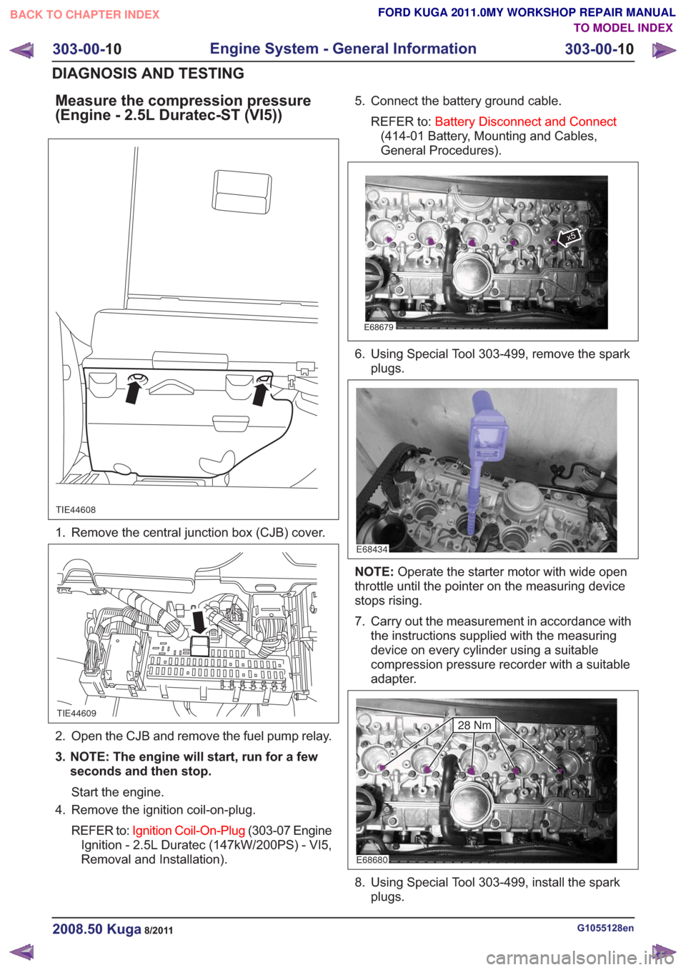
Measure the compression pressure
(Engine - 2.5L Duratec-ST (VI5))
TIE44608
1. Remove the central junction box (CJB) cover.
TIE44609
2. Open the CJB and remove the fuel pump relay.
3. NOTE: The engine will start, run for a fewseconds and then stop.
Start the engine.
4. Remove the ignition coil-on-plug.
REFER to: Ignition Coil-On-Plug (303-07 Engine
Ignition - 2.5L Duratec (147kW/200PS) - VI5,
Removal and Installation). 5. Connect the battery ground cable.
REFER to: Battery Disconnect and Connect
(414-01 Battery, Mounting and Cables,
General Procedures).
E68679
x5
6. Using Special Tool 303-499, remove the spark plugs.
E68434
NOTE: Operate the starter motor with wide open
throttle until the pointer on the measuring device
stops rising.
7. Carry out the measurement in accordance with the instructions supplied with the measuring
device on every cylinder using a suitable
compression pressure recorder with a suitable
adapter.
E68680
28 Nm
8. Using Special Tool 303-499, install the sparkplugs.
G1055128en2008.50 Kuga8/2011
303-00- 10
Engine System - General Information
303-00- 10
DIAGNOSIS AND TESTING
TO MODEL INDEX
BACK TO CHAPTER INDEX
FORD KUGA 2011.0MY WORKSHOP REPAIR MANUAL
Page 1753 of 2057
Starting System
Refer toWiring Diagrams Section 303-06, for
schematic and connector information.
General Equipment
Ford diagnostic equipment
Inspection and Verification
1. Verify the customer concern.
2. Visually inspect for obvious signs of electrical damage.
Visual Inspection Chart
Electrical
• Fuse(s)
• Wiring harness
• Electrical connector(s)
• Relay
• Switch(es)
• Battery junction box (BJB)
• Engine junction box (EJB)
• Central junction box (CJB)
• Keyless vehicle module (KVM) (if equipped)
• Battery
• Starter motor
• Powertrain Control Module (PCM)
3. If an obvious cause for an observed or reported concern is found, correct the cause (if possible)
before proceeding to the next step.
4. If the cause is not visually evident, verify the symptom and refer to the diagnostictab within
the Ford diagnostic equipment .
G1183444en2008.50 Kuga8/2011
303-06-9
Starting System— 2.5L Duratec (147kW/200PS) - VI5303-06-
9
DIAGNOSIS AND TESTING
TO MODEL INDEX
BACK TO CHAPTER INDEX
FORD KUGA 2011.0MY WORKSHOP REPAIR MANUAL
Page 1791 of 2057
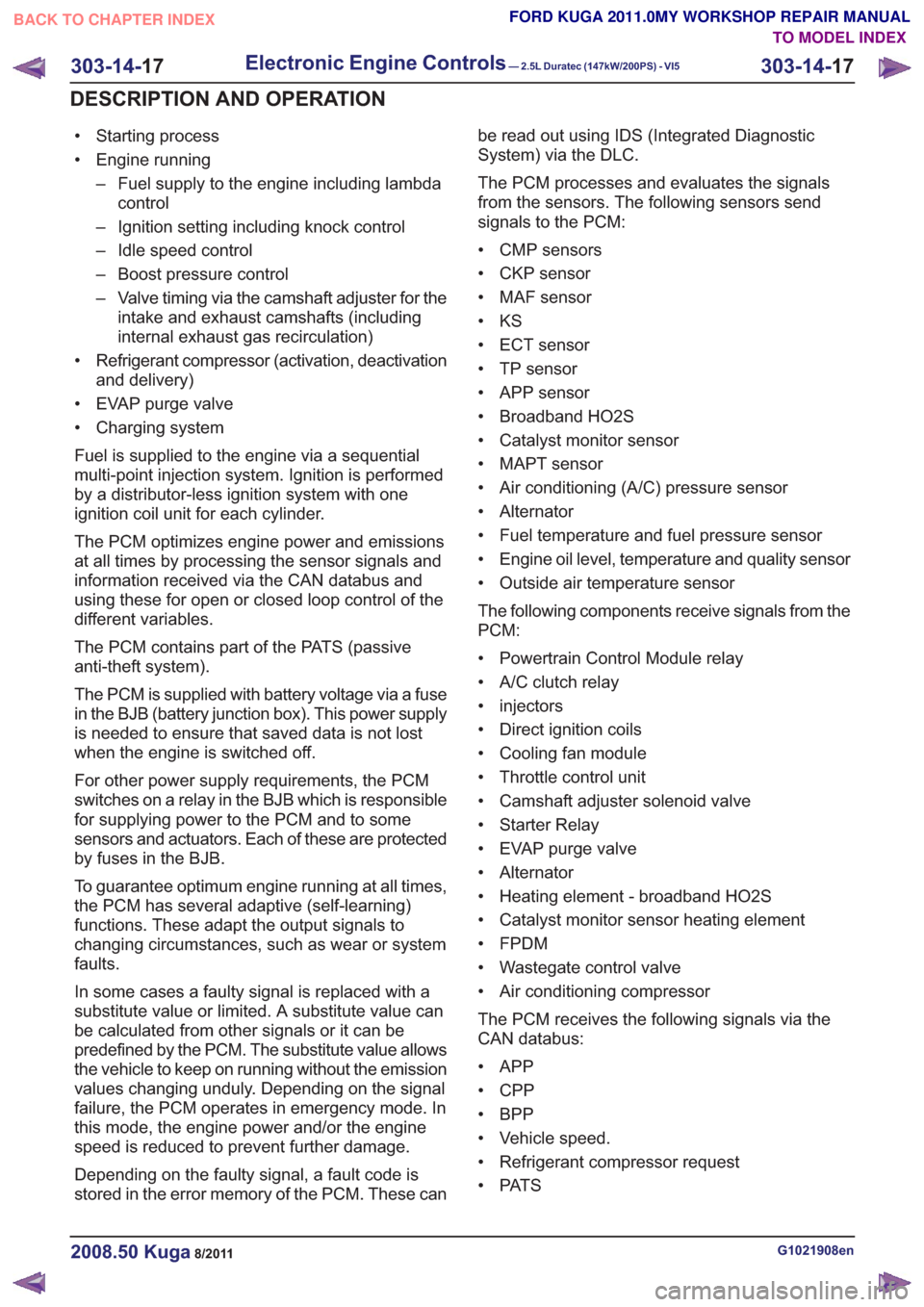
• Starting process
• Engine running– Fuel supply to the engine including lambdacontrol
– Ignition setting including knock control
– Idle speed control
– Boost pressure control
– Valve timing via the camshaft adjuster for the intake and exhaust camshafts (including
internal exhaust gas recirculation)
• Refrigerant compressor (activation, deactivation and delivery)
• EVAP purge valve
• Charging system
Fuel is supplied to the engine via a sequential
multi-point injection system. Ignition is performed
by a distributor-less ignition system with one
ignition coil unit for each cylinder.
The PCM optimizes engine power and emissions
at all times by processing the sensor signals and
information received via the CAN databus and
using these for open or closed loop control of the
different variables.
The PCM contains part of the PATS (passive
anti-theft system).
The PCM is supplied with battery voltage via a fuse
in the BJB (battery junction box). This power supply
is needed to ensure that saved data is not lost
when the engine is switched off.
For other power supply requirements, the PCM
switches on a relay in the BJB which is responsible
for supplying power to the PCM and to some
sensors and actuators. Each of these are protected
by fuses in the BJB.
To guarantee optimum engine running at all times,
the PCM has several adaptive (self-learning)
functions. These adapt the output signals to
changing circumstances, such as wear or system
faults.
In some cases a faulty signal is replaced with a
substitute value or limited. A substitute value can
be calculated from other signals or it can be
predefined by the PCM. The substitute value allows
the vehicle to keep on running without the emission
values changing unduly. Depending on the signal
failure, the PCM operates in emergency mode. In
this mode, the engine power and/or the engine
speed is reduced to prevent further damage.
Depending on the faulty signal, a fault code is
stored in the error memory of the PCM. These can be read out using IDS (Integrated Diagnostic
System) via the DLC.
The PCM processes and evaluates the signals
from the sensors. The following sensors send
signals to the PCM:
• CMP sensors
• CKP sensor
• MAF sensor
•KS
• ECT sensor
• TP sensor
• APP sensor
• Broadband HO2S
• Catalyst monitor sensor
• MAPT sensor
• Air conditioning (A/C) pressure sensor
• Alternator
• Fuel temperature and fuel pressure sensor
• Engine oil level, temperature and quality sensor
• Outside air temperature sensor
The following components receive signals from the
PCM:
• Powertrain Control Module relay
• A/C clutch relay
• injectors
• Direct ignition coils
• Cooling fan module
• Throttle control unit
• Camshaft adjuster solenoid valve
• Starter Relay
• EVAP purge valve
• Alternator
• Heating element - broadband HO2S
• Catalyst monitor sensor heating element
• FPDM
• Wastegate control valve
• Air conditioning compressor
The PCM receives the following signals via the
CAN databus:
• APP
•CPP
• BPP
• Vehicle speed.
• Refrigerant compressor request
• PAT S
G1021908en2008.50 Kuga8/2011
303-14-
17
Electronic Engine Controls— 2.5L Duratec (147kW/200PS) - VI5303-14-
17
DESCRIPTION AND OPERATION
TO MODEL INDEX
BACK TO CHAPTER INDEX
FORD KUGA 2011.0MY WORKSHOP REPAIR MANUAL
Page 2010 of 2057
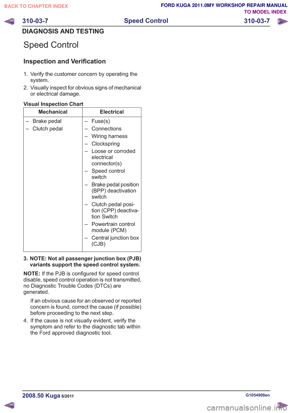
Speed Control
Inspection and Verification
1. Verify the customer concern by operating thesystem.
2. Visually inspect for obvious signs of mechanical or electrical damage.
Visual Inspection Chart
Electrical
Mechanical
– Fuse(s)
– Connections
– Wiring harness
– Clockspring
– Loose or corrodedelectrical
connector(s)
– Speed control switch
– Brake pedal position (BPP) deactivation
switch
– Clutch pedal posi- tion (CPP) deactiva-
tion Switch
– Powertrain control module (PCM)
– Central junction box (CJB)
– Brake pedal
– Clutch pedal
3. NOTE: Not all passenger junction box (PJB) variants support the speed control system.
NOTE: If the PJB is configured for speed control
disable, speed control operation is not transmitted,
no Diagnostic Trouble Codes (DTCs) are
generated.
If an obvious cause for an observed or reported
concern is found, correct the cause (if possible)
before proceeding to the next step.
4. If the cause is not visually evident, verify the symptom and refer to the diagnostic tab within
the Ford approved diagnostic tool.
G1054908en2008.50 Kuga8/2011
310-03- 7
Speed Control
310-03- 7
DIAGNOSIS AND TESTING
TO MODEL INDEX
BACK TO CHAPTER INDEX
FORD KUGA 2011.0MY WORKSHOP REPAIR MANUAL
Page 2015 of 2057
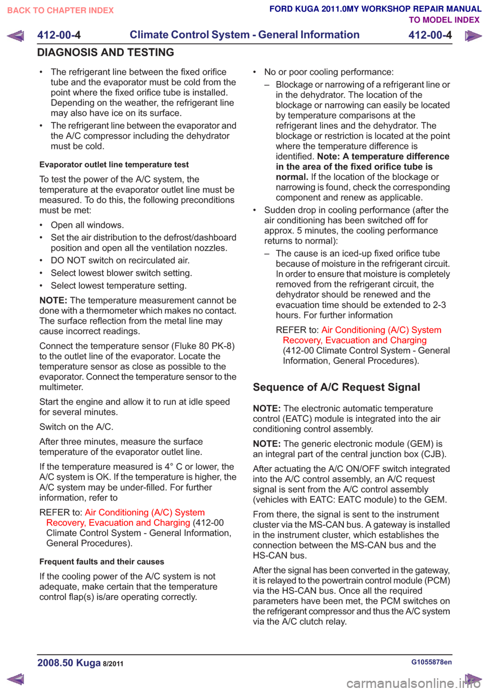
• The refrigerant line between the fixed orificetube and the evaporator must be cold from the
point where the fixed orifice tube is installed.
Depending on the weather, the refrigerant line
may also have ice on its surface.
• The refrigerant line between the evaporator and the A/C compressor including the dehydrator
must be cold.
Evaporator outlet line temperature test
To test the power of the A/C system, the
temperature at the evaporator outlet line must be
measured. To do this, the following preconditions
must be met:
• Open all windows.
• Set the air distribution to the defrost/dashboardposition and open all the ventilation nozzles.
• DO NOT switch on recirculated air.
• Select lowest blower switch setting.
• Select lowest temperature setting.
NOTE: The temperature measurement cannot be
done with a thermometer which makes no contact.
The surface reflection from the metal line may
cause incorrect readings.
Connect the temperature sensor (Fluke 80 PK-8)
to the outlet line of the evaporator. Locate the
temperature sensor as close as possible to the
evaporator. Connect the temperature sensor to the
multimeter.
Start the engine and allow it to run at idle speed
for several minutes.
Switch on the A/C.
After three minutes, measure the surface
temperature of the evaporator outlet line.
If the temperature measured is 4° C or lower, the
A/C system is OK. If the temperature is higher, the
A/C system may be under-filled. For further
information, refer to
REFER to: Air Conditioning (A/C) System
Recovery, Evacuation and Charging (412-00
Climate Control System - General Information,
General Procedures).
Frequent faults and their causes
If the cooling power of the A/C system is not
adequate, make certain that the temperature
control flap(s) is/are operating correctly. • No or poor cooling performance:
– Blockage or narrowing of a refrigerant line orin the dehydrator. The location of the
blockage or narrowing can easily be located
by temperature comparisons at the
refrigerant lines and the dehydrator. The
blockage or restriction is located at the point
where the temperature difference is
identified. Note: A temperature difference
in the area of the fixed orifice tube is
normal. If the location of the blockage or
narrowing is found, check the corresponding
component and renew as applicable.
• Sudden drop in cooling performance (after the air conditioning has been switched off for
approx. 5 minutes, the cooling performance
returns to normal):
– The cause is an iced-up fixed orifice tubebecause of moisture in the refrigerant circuit.
In order to ensure that moisture is completely
removed from the refrigerant circuit, the
dehydrator should be renewed and the
evacuation time should be extended to 2-3
hours. For further information
REFER to: Air Conditioning (A/C) System
Recovery, Evacuation and Charging
(412-00 Climate Control System - General
Information, General Procedures).
Sequence of A/C Request Signal
NOTE: The electronic automatic temperature
control (EATC) module is integrated into the air
conditioning control assembly.
NOTE: The generic electronic module (GEM) is
an integral part of the central junction box (CJB).
After actuating the A/C ON/OFF switch integrated
into the A/C control assembly, an A/C request
signal is sent from the A/C control assembly
(vehicles with EATC: EATC module) to the GEM.
From there, the signal is sent to the instrument
cluster via the MS-CAN bus. A gateway is installed
in the instrument cluster, which establishes the
connection between the MS-CAN bus and the
HS-CAN bus.
After the signal has been converted in the gateway,
it is relayed to the powertrain control module (PCM)
via the HS-CAN bus. Once all the required
parameters have been met, the PCM switches on
the refrigerant compressor and thus the A/C system
via the A/C clutch relay.
G1055878en2008.50 Kuga8/2011
412-00- 4
Climate Control System - General Information
412-00- 4
DIAGNOSIS AND TESTING
TO MODEL INDEX
BACK TO CHAPTER INDEX
FORD KUGA 2011.0MY WORKSHOP REPAIR MANUAL