ESP FORD KUGA 2011 1.G Service Manual
[x] Cancel search | Manufacturer: FORD, Model Year: 2011, Model line: KUGA, Model: FORD KUGA 2011 1.GPages: 2057
Page 1466 of 2057
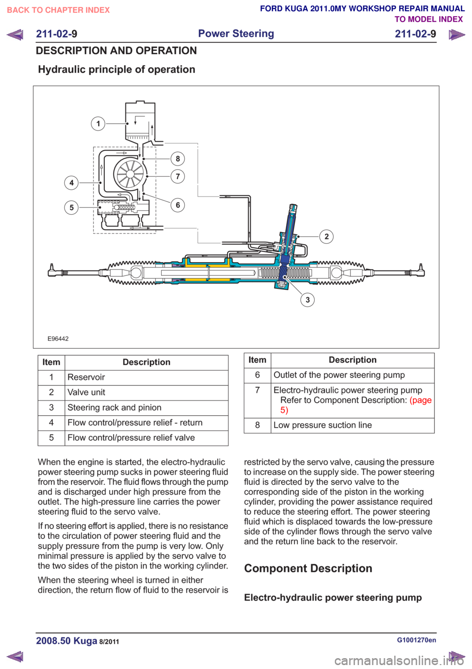
Hydraulic principle of operation
E96442
3
4
5
7
8
6
1
2
Description
Item
Reservoir
1
Valve unit
2
Steering rack and pinion
3
Flow control/pressure relief - return
4
Flow control/pressure relief valve
5Description
Item
Outlet of the power steering pump
6
Electro-hydraulic power steering pumpRefertoComponentDescription:(page
5)
7
Low pressure suction line
8
When the engine is started, the electro-hydraulic
power steering pump sucks in power steering fluid
from the reservoir. The fluid flows through the pump
and is discharged under high pressure from the
outlet. The high-pressure line carries the power
steering fluid to the servo valve.
If no steering effort is applied, there is no resistance
to the circulation of power steering fluid and the
supply pressure from the pump is very low. Only
minimal pressure is applied by the servo valve to
the two sides of the piston in the working cylinder.
When the steering wheel is turned in either
direction, the return flow of fluid to the reservoir is restricted by the servo valve, causing the pressure
to increase on the supply side. The power steering
fluid is directed by the servo valve to the
corresponding side of the piston in the working
cylinder, providing the power assistance required
to reduce the steering effort. The power steering
fluid which is displaced towards the low-pressure
side of the cylinder flows through the servo valve
and the return line back to the reservoir.
Component Description
Electro-hydraulic power steering pump
G1001270en2008.50 Kuga8/2011
211-02-
9
Power Steering
211-02- 9
DESCRIPTION AND OPERATION
TO MODEL INDEX
BACK TO CHAPTER INDEX
FORD KUGA 2011.0MY WORKSHOP REPAIR MANUAL
Page 1546 of 2057
Description
Item
Exhaust camshaft
1
intake camshaft
2
Valve cover
3
CMP Sensor - intake camshaft
4Description
Item
Intake camshaft reference mark
5
Exhaust camshaft reference mark
6
CMP Sensor - exhaust camshaft
7
CAUTION: Before removal, mark the
camshafts as the intake and exhaust
camshafts can be mixed up.
A reference mark for the CMP sensor is machined
into each camshaft. When the camshafts are set
precisely to the timing marks, the machined mark
on the exhaust camshaft is located roughly at the
5 o'clock position and the machined mark on the
intake camshaft is located at 8 o'clock.
When changing the toothed belts it is not necessary
to dismantle the camshaft adjustment units. A
special tool prevents the VCT control units from
turning during the adjustment process by locking
the two VCT control units to one another.
A further special tool is needed to fix the camshafts
in the adjustment position. The special tool
engages in corresponding recesses for the
reference marks on the CMP sensors. Each camshaft is fixed in place using four bearing
caps and the bearing cap VVT. The bearing caps
must not be changed around and must always be
fitted in their original positions.
The VCT control units for the intake and exhaust
camshafts are moved into the locked base position
when the engine is stopped through the
engagement of a spring-loaded locking pin. The
movement to the locked base position is assisted
by the tensile force of the timing belt for the intake
VCT control unit. With the exhaust VCT control
unit, a spring inside the control unit additionally
assists in reaching the locked base position. The
intake VCT control unit is in the "retarded timing"
position and the exhaust VCT control unit is in the
"advanced timing" position when in the locked base
position. The lock is hydraulically released when
the engine is started depending on the oil pressure.
The mechanical valve tappets are maintenance
free.
G1092773en2008.50 Kuga8/2011
303-01-
13
Engine— 2.5L Duratec (147kW/200PS) - VI5303-01-
13
DESCRIPTION AND OPERATION
TO MODEL INDEX
BACK TO CHAPTER INDEX
FORD KUGA 2011.0MY WORKSHOP REPAIR MANUAL
Page 1723 of 2057
Recirculated air valve
E97052
43
2
1
Description
Item
Recirculated air valve
1
Vacuum hose to intake manifold
2
Air ingress
3
Air discharge
4
If the throttle valve is closed quickly, the moving
air column hits the throttle valve. The air column
is reversed, flows back onto the rotating impeller
of the TC and powerfully decelerates it. A
recirculated air valve is installed to prevent this
deceleration of the impeller and thus allow the TC
to respond faster. The recirculated air valve is
controlled via a vacuum line which is connected to
the intake manifold. When the throttle valve is
suddenly closed, a high vacuum occurs in the
intake manifold. This opens the recirculated air
valve and the compressed air is returned to a point
before the compressor. This causes the speed of
the turbocharger to drop less rapidly and the boost
pressure can build up more rapidly when the
accelerator pedal is pressed again.
Component Description
Wastegate control valve
1
2
3
E98852
Description
Item
from turbocharger (boost pressure)
1
from turbocharger (atmospheric pressure)
2
to boost pressure regulator (control
pressure)
3
The wastegate control valve operates as a cycle
valve. The pressure acting on the membrane in
the boost pressure regulator is controlled by
appropriate pulsing of the wastegate control valve.
The pressure acting on the membrane in the boost
pressure regulator is reduced when the wastegate
control valve opens.
The operating voltage of the wastegate control
valve is 12V.
The internal resistance of the wastegate control
valve is 28.5 ± 1.5 Ohms.
The operating states are:
• De-energised: gate open between 1 and 3 – Boost pressure high > wastegate controlvalve closed > boost pressure regulator open
> turbine receives restricted exhaust gas
flow.
• Energised: gate open between 2 and 3 – Boost pressure low > wastegate control valveopen > boost pressure regulator closed >
turbine receives full exhaust gas flow.
G1032426en2008.50 Kuga8/2011
303-04B- 7
Fuel Charging and Controls - Turbocharger
—
2.5L Duratec (147kW/200PS) - VI5
303-04B- 7
DESCRIPTION AND OPERATION
TO MODEL INDEX
BACK TO CHAPTER INDEX
FORD KUGA 2011.0MY WORKSHOP REPAIR MANUAL
Page 1740 of 2057
alignment. INSTALL a new accessory drive belt
tensioner as necessary.
REFER to:Accessory Drive Belt Tensioner
(303-05 Accessory Drive - 2.5L Duratec
(147kW/200PS) - VI5, Removal and
Installation).
or
REFER to: Air Conditioning (A/C) Compressor
Belt Tensioner (303-05 Accessory Drive - 2.5L
Duratec (147kW/200PS) - VI5, Removal and
Installation).
TEST the system for normal operation.
5. If the accessory drive belt tensioner meets the above criteria, proceed to test the accessory
drive belt tensioner dynamically. If the accessory
drive belt tensioner does not meet the above
criteria, INSTALL a new accessory drive belt
tensioner.
REFER to: Accessory Drive Belt Tensioner
(303-05 Accessory Drive - 2.5L Duratec
(147kW/200PS) - VI5, Removal and
Installation).
or
REFER to: Air Conditioning (A/C) Compressor
Belt Tensioner (303-05 Accessory Drive - 2.5L
Duratec (147kW/200PS) - VI5, Removal and
Installation).
TEST the system for normal operation.
Accessory Drive Belt Tensioner - Dynamic
Check
The accessory drive belt tensioner may be checked
dynamically as follows:
1. With the engine running, observe the accessory drive belt tensioner movement. The accessory
drive belt tensioner should move (respond)
when the engine is accelerated rapidly or when
the A/C clutch cycles ON and OFF (the degree
of movement can be up to 4 mm). If the
accessory drive belt tensioner movement is not
constant without engine acceleration or A/C
clutch cycling, a pulley or shaft is possibly bent,
out of round, or the damping mechanism inside
the accessory drive belt tensioner may be
damaged. INSTALL a new accessory drive belt
tensioner as necessary.
REFER to: Accessory Drive Belt Tensioner
(303-05 Accessory Drive - 2.5L Duratec
(147kW/200PS) - VI5, Removal and
Installation). or
REFER to:
Air Conditioning (A/C) Compressor
Belt Tensioner (303-05 Accessory Drive - 2.5L
Duratec (147kW/200PS) - VI5, Removal and
Installation).
TEST the system for normal operation.
2. Excessive accessory drive belt rideout (uneven depth of grooves in the accessory drive belt)
may cause excessive accessory drive belt
tensioner movement. Check the condition by
installing a new accessory drive belt.
REFER to: Accessory Drive Belt (303-05
Accessory Drive - 2.5L Duratec
(147kW/200PS) - VI5, Removal and
Installation).
and/or
REFER to: Air Conditioning (A/C) Compressor
Belt (303-05 Accessory Drive - 2.5L Duratec
(147kW/200PS) - VI5, Removal and
Installation).
TEST the system for normal operation.
G1183443en2008.50 Kuga8/2011
303-05- 10
Accessory Drive— 2.5L Duratec (147kW/200PS) - VI5303-05-
10
DIAGNOSIS AND TESTING
TO MODEL INDEX
BACK TO CHAPTER INDEX
FORD KUGA 2011.0MY WORKSHOP REPAIR MANUAL
Page 1768 of 2057

Intake Air Distribution and Filtering
Inspection and Verification
1. Verify the customer concern.
2. Visually inspect for obvious signs of mechanicalor electrical damage.
Visual Inspection Chart
Electrical
Mechanical
– Mass air flow (MAF)sensor
– Manifold absolute pressure (MAP)
sensor
– Electrical connector(s)
– Air cleaner element
– Air cleaner intake
pipe
– Air cleaner outlet pipe
– Charge air cooler
– Charge air cooler intake pipe
– Charge air cooler outlet pipe 3. If an obvious cause for an observed or reported
concern is found, correct the cause (if possible)
before proceeding to the next step.
4. If the cause is not visually evident, verify the symptom and refer to the Symptom Chart.
Symptom Chart
Action
Possible Sources
Symptom
• CHECK the pipe(s) for securityand leaks to atmosphere.
INSTALL new intake air
components as necessary.
TEST the system for normal
operation.
• Detached air cleaner pipe(s).
• Detached turbocharger pipe(s).
• Detached charge air cooler
pipe(s).
• Excessive intake air noise
• REFER to:Engine Emission
Control (303-08 Engine
Emission Control - 2.5L
Duratec (147kW/200PS) -
VI5, Diagnosis and Testing).
• Blocked or damaged PCV
pipe(s)/hose(s).
• Blocked or damaged crankcase vent oil separator.
• Oil in the air intake system
• REFER to:Turbocharger(303-
04 Fuel Charging and
Controls - Turbocharger -
2.5L Duratec (147kW/200PS)
- VI5, Diagnosis and Testing).
• Turbocharger.
• CHECK the air intake pipesplash shield for correct install-
ation and alignment.
REPAIR/INSTALL the air intake
pipe splash shield as neces-
sary. TEST the system for
normal operation.
• Air intake pipe splash shield.
• Water in the air cleaner
G1183447en2008.50 Kuga8/2011
303-12- 4
Intake Air Distribution and Filtering
— 2.5L Duratec
(147kW/200PS) - VI5
303-12- 4
DIAGNOSIS AND TESTING
TO MODEL INDEX
BACK TO CHAPTER INDEX
FORD KUGA 2011.0MY WORKSHOP REPAIR MANUAL
Page 1791 of 2057
• Starting process
• Engine running– Fuel supply to the engine including lambdacontrol
– Ignition setting including knock control
– Idle speed control
– Boost pressure control
– Valve timing via the camshaft adjuster for the intake and exhaust camshafts (including
internal exhaust gas recirculation)
• Refrigerant compressor (activation, deactivation and delivery)
• EVAP purge valve
• Charging system
Fuel is supplied to the engine via a sequential
multi-point injection system. Ignition is performed
by a distributor-less ignition system with one
ignition coil unit for each cylinder.
The PCM optimizes engine power and emissions
at all times by processing the sensor signals and
information received via the CAN databus and
using these for open or closed loop control of the
different variables.
The PCM contains part of the PATS (passive
anti-theft system).
The PCM is supplied with battery voltage via a fuse
in the BJB (battery junction box). This power supply
is needed to ensure that saved data is not lost
when the engine is switched off.
For other power supply requirements, the PCM
switches on a relay in the BJB which is responsible
for supplying power to the PCM and to some
sensors and actuators. Each of these are protected
by fuses in the BJB.
To guarantee optimum engine running at all times,
the PCM has several adaptive (self-learning)
functions. These adapt the output signals to
changing circumstances, such as wear or system
faults.
In some cases a faulty signal is replaced with a
substitute value or limited. A substitute value can
be calculated from other signals or it can be
predefined by the PCM. The substitute value allows
the vehicle to keep on running without the emission
values changing unduly. Depending on the signal
failure, the PCM operates in emergency mode. In
this mode, the engine power and/or the engine
speed is reduced to prevent further damage.
Depending on the faulty signal, a fault code is
stored in the error memory of the PCM. These can be read out using IDS (Integrated Diagnostic
System) via the DLC.
The PCM processes and evaluates the signals
from the sensors. The following sensors send
signals to the PCM:
• CMP sensors
• CKP sensor
• MAF sensor
•KS
• ECT sensor
• TP sensor
• APP sensor
• Broadband HO2S
• Catalyst monitor sensor
• MAPT sensor
• Air conditioning (A/C) pressure sensor
• Alternator
• Fuel temperature and fuel pressure sensor
• Engine oil level, temperature and quality sensor
• Outside air temperature sensor
The following components receive signals from the
PCM:
• Powertrain Control Module relay
• A/C clutch relay
• injectors
• Direct ignition coils
• Cooling fan module
• Throttle control unit
• Camshaft adjuster solenoid valve
• Starter Relay
• EVAP purge valve
• Alternator
• Heating element - broadband HO2S
• Catalyst monitor sensor heating element
• FPDM
• Wastegate control valve
• Air conditioning compressor
The PCM receives the following signals via the
CAN databus:
• APP
•CPP
• BPP
• Vehicle speed.
• Refrigerant compressor request
• PAT S
G1021908en2008.50 Kuga8/2011
303-14-
17
Electronic Engine Controls— 2.5L Duratec (147kW/200PS) - VI5303-14-
17
DESCRIPTION AND OPERATION
TO MODEL INDEX
BACK TO CHAPTER INDEX
FORD KUGA 2011.0MY WORKSHOP REPAIR MANUAL
Page 1793 of 2057
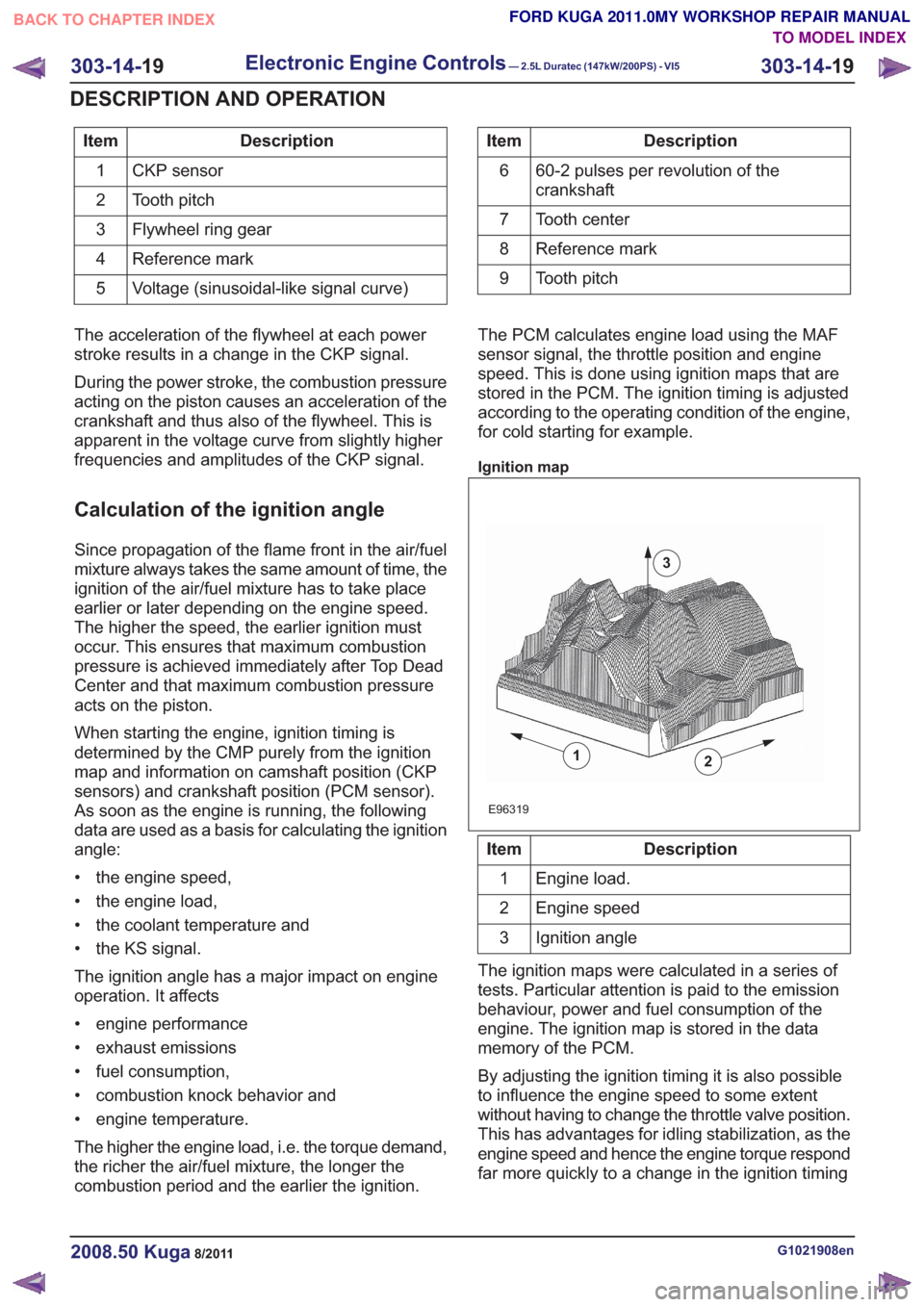
Description
Item
CKP sensor
1
Tooth pitch
2
Flywheel ring gear
3
Reference mark
4
Voltage (sinusoidal-like signal curve)
5Description
Item
60-2 pulses per revolution of the
crankshaft
6
Tooth center
7
Reference mark
8
Tooth pitch
9
The acceleration of the flywheel at each power
stroke results in a change in the CKP signal.
During the power stroke, the combustion pressure
acting on the piston causes an acceleration of the
crankshaft and thus also of the flywheel. This is
apparent in the voltage curve from slightly higher
frequencies and amplitudes of the CKP signal.
Calculation of the ignition angle
Since propagation of the flame front in the air/fuel
mixture always takes the same amount of time, the
ignition of the air/fuel mixture has to take place
earlier or later depending on the engine speed.
The higher the speed, the earlier ignition must
occur. This ensures that maximum combustion
pressure is achieved immediately after Top Dead
Center and that maximum combustion pressure
acts on the piston.
When starting the engine, ignition timing is
determined by the CMP purely from the ignition
map and information on camshaft position (CKP
sensors) and crankshaft position (PCM sensor).
As soon as the engine is running, the following
data are used as a basis for calculating the ignition
angle:
• the engine speed,
• the engine load,
• the coolant temperature and
• the KS signal.
The ignition angle has a major impact on engine
operation. It affects
• engine performance
• exhaust emissions
• fuel consumption,
• combustion knock behavior and
• engine temperature.
The higher the engine load, i.e. the torque demand,
the richer the air/fuel mixture, the longer the
combustion period and the earlier the ignition. The PCM calculates engine load using the MAF
sensor signal, the throttle position and engine
speed. This is done using ignition maps that are
stored in the PCM. The ignition timing is adjusted
according to the operating condition of the engine,
for cold starting for example.
Ignition map
2
E96319
1
3
Description
Item
Engine load.
1
Engine speed
2
Ignition angle
3
The ignition maps were calculated in a series of
tests. Particular attention is paid to the emission
behaviour, power and fuel consumption of the
engine. The ignition map is stored in the data
memory of the PCM.
By adjusting the ignition timing it is also possible
to influence the engine speed to some extent
without having to change the throttle valve position.
This has advantages for idling stabilization, as the
engine speed and hence the engine torque respond
far more quickly to a change in the ignition timing
G1021908en2008.50 Kuga8/2011
303-14- 19
Electronic Engine Controls— 2.5L Duratec (147kW/200PS) - VI5303-14-
19
DESCRIPTION AND OPERATION
TO MODEL INDEX
BACK TO CHAPTER INDEX
FORD KUGA 2011.0MY WORKSHOP REPAIR MANUAL
Page 1794 of 2057
than to a change in the throttle valve position. The
ignition timing also changes much more quickly.
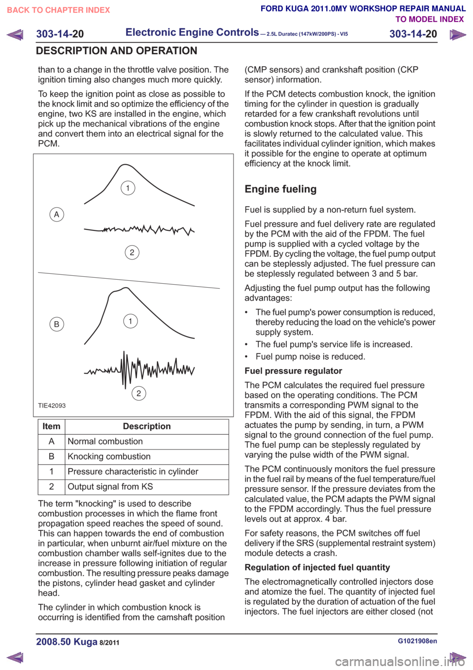
To keep the ignition point as close as possible to
the knock limit and so optimize the efficiency of the
engine, two KS are installed in the engine, which
pick up the mechanical vibrations of the engine
and convert them into an electrical signal for the
PCM.
TIE42093
1
2
A
B1
2
Description
Item
Normal combustion
A
Knocking combustion
B
Pressure characteristic in cylinder
1
Output signal from KS
2
The term "knocking" is used to describe
combustion processes in which the flame front
propagation speed reaches the speed of sound.
This can happen towards the end of combustion
in particular, when unburnt air/fuel mixture on the
combustion chamber walls self-ignites due to the
increase in pressure following initiation of regular
combustion. The resulting pressure peaks damage
the pistons, cylinder head gasket and cylinder
head.
The cylinder in which combustion knock is
occurring is identified from the camshaft position (CMP sensors) and crankshaft position (CKP
sensor) information.
If the PCM detects combustion knock, the ignition
timing for the cylinder in question is gradually
retarded for a few crankshaft revolutions until
combustion knock stops. After that the ignition point
is slowly returned to the calculated value. This
facilitates individual cylinder ignition, which makes
it possible for the engine to operate at optimum
efficiency at the knock limit.
Engine fueling
Fuel is supplied by a non-return fuel system.
Fuel pressure and fuel delivery rate are regulated
by the PCM with the aid of the FPDM. The fuel
pump is supplied with a cycled voltage by the
FPDM. By cycling the voltage, the fuel pump output
can be steplessly adjusted. The fuel pressure can
be steplessly regulated between 3 and 5 bar.
Adjusting the fuel pump output has the following
advantages:
• The fuel pump's power consumption is reduced,
thereby reducing the load on the vehicle's power
supply system.
• The fuel pump's service life is increased.
• Fuel pump noise is reduced.
Fuel pressure regulator
The PCM calculates the required fuel pressure
based on the operating conditions. The PCM
transmits a corresponding PWM signal to the
FPDM. With the aid of this signal, the FPDM
actuates the pump by sending, in turn, a PWM
signal to the ground connection of the fuel pump.
The fuel pump can be steplessly regulated by
varying the pulse width of the PWM signal.
The PCM continuously monitors the fuel pressure
in the fuel rail by means of the fuel temperature/fuel
pressure sensor. If the pressure deviates from the
calculated value, the PCM adapts the PWM signal
to the FPDM accordingly. Thus the fuel pressure
levels out at approx. 4 bar.
For safety reasons, the PCM switches off fuel
delivery if the SRS (supplemental restraint system)
module detects a crash.
Regulation of injected fuel quantity
The electromagnetically controlled injectors dose
and atomize the fuel. The quantity of injected fuel
is regulated by the duration of actuation of the fuel
injectors. The fuel injectors are either closed (not
G1021908en2008.50 Kuga8/2011
303-14- 20
Electronic Engine Controls— 2.5L Duratec (147kW/200PS) - VI5303-14-
20
DESCRIPTION AND OPERATION
TO MODEL INDEX
BACK TO CHAPTER INDEX
FORD KUGA 2011.0MY WORKSHOP REPAIR MANUAL
Page 1795 of 2057
actuated) or opened (actuated). Each cylinder has
its own injector. The injection is accurately dosed
and takes place at a time determined by the PCM.
Injection takes place immediately in front of the
intake valves of the cylinder. The injectors are
actuated ground side via end-stages integrated
into the PCM and using the signal calculated by
the engine management system. Power is supplied
via the Powertrain Control Module relay in the BJB.
The injected fuel quantity depends on the opening
time, the fuel pressure and the diameter of the
nozzle holes.
The fuel metering is determined via open or
closed-loop control.
The open control loop differs from the closed
control loop in that the lambda control is
deactivated.
The PCM switches from closed to open-loop control
if the HO2S cools down to below 600°C or fails, as
well as when accelerating, coasting and at full load.
Regulation of injected fuel quantity via the PCM
involves:
• controlling the fuel pump,
• calculating the required quantity of fuel forengine starting,
• observance of the desired air/fuel ratio,
• calculating air mass,
• and calculating the fuel quantity for the different operating states and corresponding fuel
adjustment measures.
Open loop control
Open loop control is used primarily for fuel
injection, as long as the signals of the HO2S are
not involved in the calculation of the PCM.
The two most important reasons that make it
absolutely essential to run the engine without
lambda control (open-loop control) are the following
operating conditions:
• Cold engine (starting, warm-up phase)
• Full-load operation (WOT (wide open throttle))
Under these operating conditions the engine needs
a rich air/fuel mixture with lambda values below λ
= 1 in order to achieve optimum running or
optimum performance.
It is possible to keep this unregulated range very
small by using a broadband HO2S.
Closed-loop control
Closed loop control ensures strict control of
exhaust emissions in conjunction with the TWC (three-way catalytic converter) and economical fuel
consumption. With closed loop control, the signals
from the HO2S are analyzed by the PCM and the
engine always runs in the optimum range of λ = 1.
In addition to the normal HO2S, the signal from the
monitoring sensor for the catalytic converter is also
included in the control. The lambda control is
optimized on the basis of this data.
Certain factors such as wear, component
tolerances or more minor defects such as air leaks
in the intake system are compensated for by
lambda control. If the deviation occurs for a longer
period of time, this is recorded by the adaptive
(self-learning) function of lambda control. In this
instance, the entire map is shifted by the
corresponding amount, to enable control to
commence once again from the virtual baseline.
These adaptive settings are stored in the PCM and
are also used in open-loop control conditions.
If the adaptive value is too high or too low, an error
is stored in the fault memory of the PCM.
Oxygen sensor (HO2S) and catalyst monitor
sensor
A broadband HO2S is used as the HO2S. The
HO2S is located in front of the TWC. The catalyst
monitor sensor is located in the center of the TWC
so that it can detect any deterioration in the
cleaning performance of the TWC more quickly.
The HO2S measures the residual amount of
oxygen in the exhaust before the TWC.
The catalyst monitor sensor measures the amount
of oxygen in the exhaust gas after or in the TWC.
Both the HO2S and the catalyst monitor sensor
transmit these data to the PCM.
The broadband HO2S works at temperatures of
between 650°C and 900 °C. If the temperature
rises above 1000°C, the oxygen sensor will be
irreparably damaged.
To reach optimum operating temperature as quickly
as possible, an electrically-heated oxygen sensor
is installed. The heating also serves to maintain a
suitable operating temperature while coasting, for
example, when no hot gases are flowing past the
oxygen sensor.
The heating element in the HO2S is a PTC
(positive temperature coefficient) resistor. The
heating element is supplied with battery voltage as
soon as the Powertrain Control Module relay
engages. The HO2S is earthed via the PCM. As
the heating current is high when the element is
cold, it is limited via PWM in the PCM until a certain
G1021908en2008.50 Kuga8/2011
303-14-
21
Electronic Engine Controls— 2.5L Duratec (147kW/200PS) - VI5303-14-
21
DESCRIPTION AND OPERATION
TO MODEL INDEX
BACK TO CHAPTER INDEX
FORD KUGA 2011.0MY WORKSHOP REPAIR MANUAL
Page 1796 of 2057
current value is reached. The PCM then
permanently connects the heating element to earth.
The catalyst monitor sensor is used by the PCM
to measure the oxygen content in the exhaust gas
in the TWC. If all the conditions for catalyst
diagnostics are met, based on this information the
PCM can check that the TWC is working
satisfactorily. The information is also used to
improve the air/fuel mixture adjustment.
The catalyst monitor sensor is similar in function
to an HO2S. The signal transmitted by the catalyst
monitor sensor changes sharply if the oxygen
content in the exhaust gas changes. For this
reason, catalyst monitor sensors are also called
"jump lambda sensors".
Fuel tank purging
The EVAP purge valve is only actuated by the PCM
if the coolant temperature is at least 60°C.
Actuation is done ground side by means of a PWM
signal. This makes it possible to have the full range
of opening widths, from fully closed to fully open.
The PCM determines from the operating conditions
when and how wide to open the EVAP tank purge
valve. If the EVAP purge valve is opened, the
engine sucks in ambient air through the activated
charcoal in the evaporative emission canister as
a result of the vacuum in the intake manifold. In
this way the adsorbed hydrocarbons are led to the
combustion chamber of the engine.
The EVAP tank purge valve is not actuated and
system cleaning is interrupted if the engine
switches to idle and/or a closed-loop control
process is initiated.
Power (battery voltage) is supplied via the
Powertrain Control Module relay in the BJB. The
solenoid coil resistance is between 17 and 24 ohms
at 20°C.
Engine speed control
The APP sensor provides the PCM with information
about the driver's request for acceleration.
The throttle control unit receives a corresponding
input signal from the PCM. An electric motor then
moves the throttle valve shaft by means of a set
of gears. The position of the throttle is continuously
recorded by the TP sensor. Information on throttle
position is processed and monitored by the PCM.
The TP sensor comprises two potentiometers.
These work in opposite ways to each other. In one
potentiometer, the resistance increases when the
throttle is opened, in the other it decreases. Thisallows the operation of the potentiometers to be
checked. The signal from the TP sensor is
amplified in the lower range (idle to a quarter open)
by the PCM to enable more precise control of the
throttle in this range. This is necessary because
the engine is very sensitive to changes in throttle
angle in this throttle opening range.
With the throttle valve position kept constant, the
ignition angle and the injected fuel quantity are
then varied to meet the torque demands.
Depending on the operating state of the engine, a
change in the position of the throttle flap may not
be necessary when the APP sensor changes.
If a fault develops in the throttle control unit, a
standby function is executed. This standby function
allows a slight opening of the throttle flap, so that
enough air passes through to allow limited engine
operation. For this purpose, there is a throttle flap
adjustment screw on the throttle housing. The
return spring closes the throttle flap until the stop
of the toothed segment touches the stop screw. In
this way a defined throttle flap gap is formed for
limp home mode.
The stop screw has a spring loaded pin, which
holds the throttle flap open for limp home mode.
In normal operating mode, this spring loaded pin
is pushed in by the force of the electric motor when
the throttle flap must be closed past the limp home
position (e.g. for idle speed control or overrun
shutoff).
Oil monitoring
The engine does not have an oil pressure
switch.
The oil level and oil quality are calculated.
Calculating the engine oil level
The oil level is determined by continuous
measurement of the capacitance (i.e. the ability to
store an electrical charge) between the two
capacitive elements of the engine oil
level/temperature/quality sensor. The different oil
levels cause the capacitance between the elements
to change. The data are recorded by the PCM and
converted into an oil level value. Temporary
fluctuations in oil level are automatically filtered out
by the PCM.
Calculating oil quality
The PCM calculates the oil quality from the oil level
measurement and the oil temperature measured
by the sensor, plus the engine speed and the
average fuel consumption. The driver is informed
about when an oil change is due.
G1021908en2008.50 Kuga8/2011
303-14- 22
Electronic Engine Controls— 2.5L Duratec (147kW/200PS) - VI5303-14-
22
DESCRIPTION AND OPERATION
TO MODEL INDEX
BACK TO CHAPTER INDEX
FORD KUGA 2011.0MY WORKSHOP REPAIR MANUAL