open FORD KUGA 2011 1.G Service Manual
[x] Cancel search | Manufacturer: FORD, Model Year: 2011, Model line: KUGA, Model: FORD KUGA 2011 1.GPages: 2057
Page 1261 of 2057
6
7
8
9
10
11
1
2
3
4
5
6
7
8
9
10
11
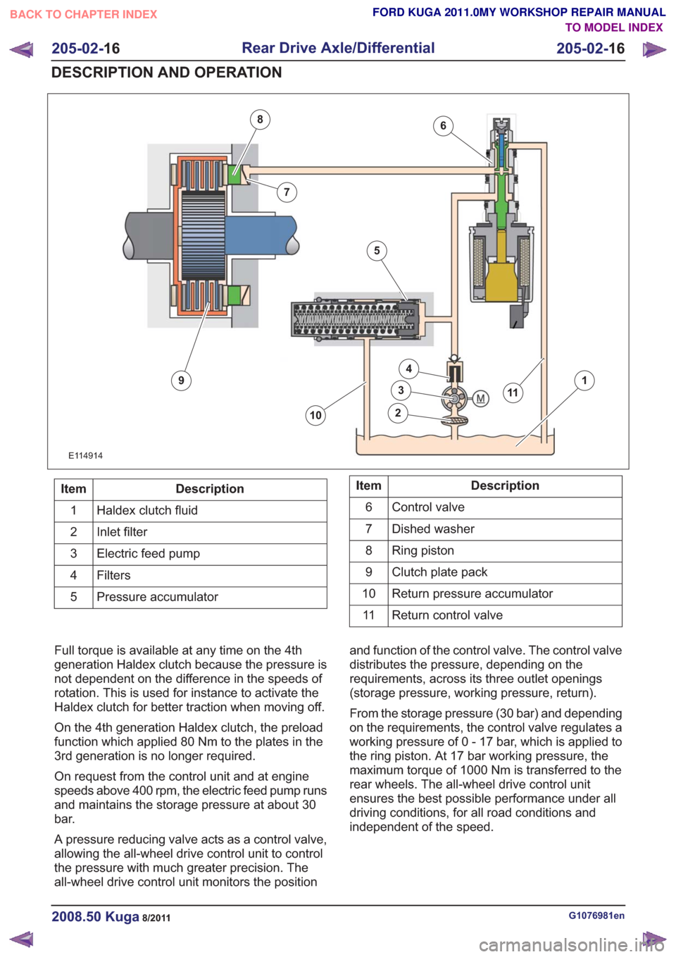
E114914
Description
Item
Haldex clutch fluid
1
Inlet filter
2
Electric feed pump
3
Filters4
Pressure accumulator
5Description
Item
Control valve
6
Dished washer
7
Ring piston
8
Clutch plate pack
9
Return pressure accumulator
10
Return control valve
11
Full torque is available at any time on the 4th
generation Haldex clutch because the pressure is
not dependent on the difference in the speeds of
rotation. This is used for instance to activate the
Haldex clutch for better traction when moving off.
On the 4th generation Haldex clutch, the preload
function which applied 80 Nm to the plates in the
3rd generation is no longer required.
On request from the control unit and at engine
speeds above 400 rpm, the electric feed pump runs
and maintains the storage pressure at about 30
bar.
A pressure reducing valve acts as a control valve,
allowing the all-wheel drive control unit to control
the pressure with much greater precision. The
all-wheel drive control unit monitors the position and function of the control valve. The control valve
distributes the pressure, depending on the
requirements, across its three outlet openings
(storage pressure, working pressure, return).
From the storage pressure (30 bar) and depending
on the requirements, the control valve regulates a
working pressure of 0 - 17 bar, which is applied to
the ring piston. At 17 bar working pressure, the
maximum torque of 1000 Nm is transferred to the
rear wheels. The all-wheel drive control unit
ensures the best possible performance under all
driving conditions, for all road conditions and
independent of the speed.
G1076981en2008.50 Kuga8/2011
205-02-
16
Rear Drive Axle/Differential
205-02- 16
DESCRIPTION AND OPERATION
TO MODEL INDEX
BACK TO CHAPTER INDEX
FORD KUGA 2011.0MY WORKSHOP REPAIR MANUAL
Page 1377 of 2057
Front Brake Flexible Hose
Removal
CAUTION:
Refer to:Brake System Health and Safety
Precautions (100-00 General Information,
Description and Operation).
NOTE: Removal steps in this procedure may
contain installation details. 1.
Refer to: Wheel and Tire (204-04 Wheels and
Tires, Removal and Installation).
2. WARNINGS:
Make sure that no load is placed on the
brake hose.
Be prepared to collect escaping fluid.
CAUTION: Make sure that all openings
are sealed.
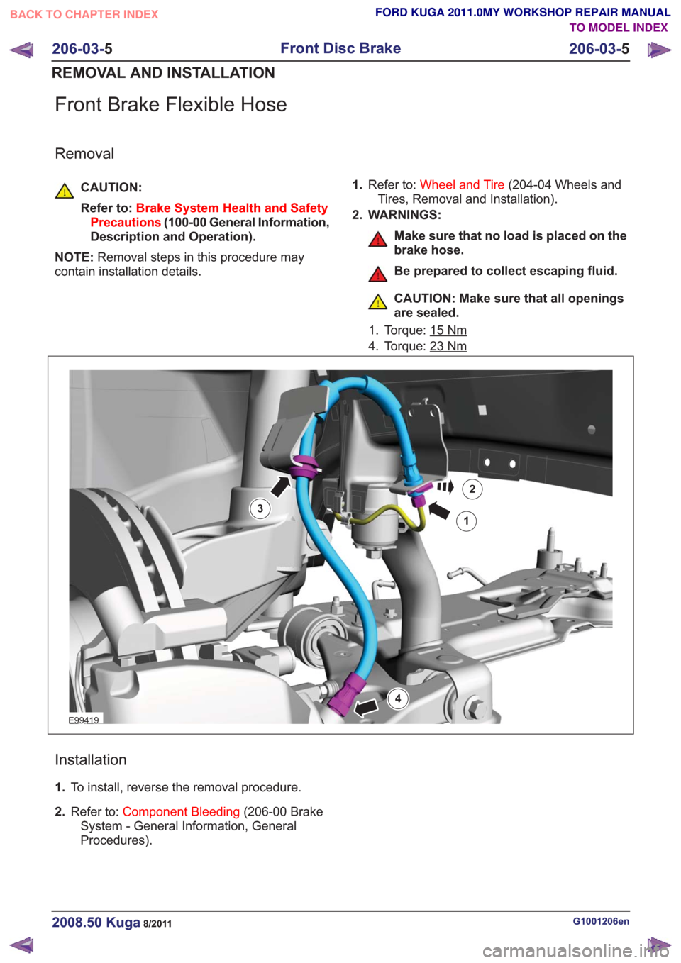
1. Torque: 15
Nm
4. Torque: 23Nm
E99419
1
2
3
4
Installation
1. To install, reverse the removal procedure.
2. Refer to: Component Bleeding (206-00 Brake
System - General Information, General
Procedures).
G1001206en2008.50 Kuga8/2011
206-03- 5
Front Disc Brake
206-03- 5
REMOVAL AND INSTALLATION
TO MODEL INDEX
BACK TO CHAPTER INDEX
FORD KUGA 2011.0MY WORKSHOP REPAIR MANUAL
Page 1381 of 2057
Brake Caliper(12 253 0)
General EquipmentHose Clamp(s)
Materials
Specification
Name
WSS-M6C57-A2
Brake Fluid - Super
DOT4
Removal
NOTE: Removal steps in this procedure may
contain installation details.
1. Refer to: Brake System Health and Safety
Precautions (100-00 General Information,
Description and Operation).
2. Refer to: Wheel and Tire (204-04 Wheels and
Tires, Removal and Installation).
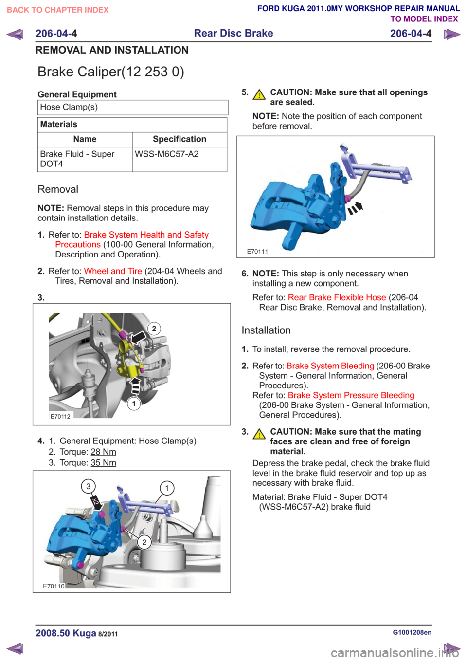
3.
E70112
1
2
4. General Equipment: Hose Clamp(s)
1.
2. Torque: 28
Nm
3. Torque: 35Nm
E70110
1
2
x2
3
5. CAUTION: Make sure that all openings
are sealed.
NOTE: Note the position of each component
before removal.
E70111
6. NOTE: This step is only necessary when
installing a new component.
Refer to: Rear Brake Flexible Hose (206-04
Rear Disc Brake, Removal and Installation).
Installation
1. To install, reverse the removal procedure.
2. Refer to: Brake System Bleeding (206-00 Brake
System - General Information, General
Procedures).
Refer to: Brake System Pressure Bleeding
(206-00 Brake System - General Information,
General Procedures).
3.
CAUTION: Make sure that the mating
faces are clean and free of foreign
material.
Depress the brake pedal, check the brake fluid
level in the brake fluid reservoir and top up as
necessary with brake fluid.
Material: Brake Fluid - Super DOT4 (WSS-M6C57-A2) brake fluid
G1001208en2008.50 Kuga8/2011
206-04- 4
Rear Disc Brake
206-04- 4
REMOVAL AND INSTALLATION
TO MODEL INDEX
BACK TO CHAPTER INDEX
FORD KUGA 2011.0MY WORKSHOP REPAIR MANUAL
Page 1382 of 2057

Rear Brake Flexible Hose
Removal
CAUTION:
Refer to:Brake System Health and Safety
Precautions (100-00 General Information,
Description and Operation).
NOTE: Removal steps in this procedure may
contain installation details. 1.
Refer to: Wheel and Tire (204-04 Wheels and
Tires, Removal and Installation).
2. WARNINGS:
Make sure that no load is placed on the
brake hose.
Be prepared to collect escaping fluid.
CAUTION: Make sure that all openings
are sealed.
1. Torque: 15
Nm
E99425
1
2
3
G1001210en2008.50 Kuga8/2011
206-04- 5
Rear Disc Brake
206-04- 5
REMOVAL AND INSTALLATION
TO MODEL INDEX
BACK TO CHAPTER INDEX
FORD KUGA 2011.0MY WORKSHOP REPAIR MANUAL
Page 1402 of 2057
Brake Master Cylinder — 2.5L Duratec (147kW/200PS) -VI5(12 343 0)
Removal
NOTE: Removal steps in this procedure may
contain installation details.
1. Refer to: Brake System Health and Safety
Precautions (100-00 General Information,
Description and Operation).
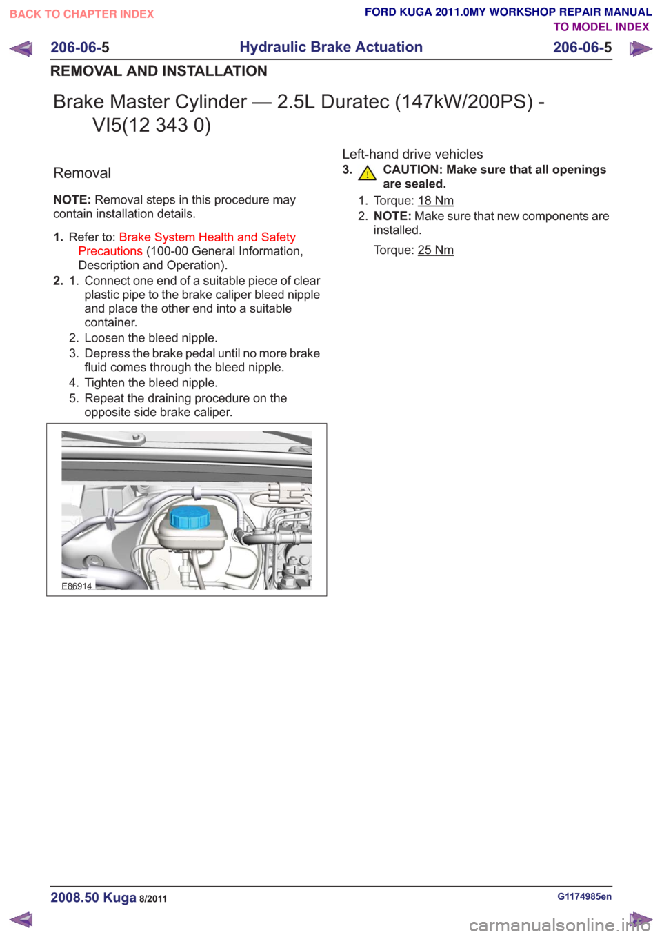
2. Connect one end of a suitable piece of clear
plastic pipe to the brake caliper bleed nipple
1.
and place the other end into a suitable
container.
2. Loosen the bleed nipple.
3. Depress the brake pedal until no more brake fluid comes through the bleed nipple.
4. Tighten the bleed nipple.
5. Repeat the draining procedure on the opposite side brake caliper.
E86914
Left-hand drive vehicles
3. CAUTION: Make sure that all openings are sealed.
1. Torque: 18Nm
2.NOTE: Make sure that new components are
installed.
Torque: 25
Nm
G1174985en2008.50 Kuga8/2011
206-06- 5
Hydraulic Brake Actuation
206-06- 5
REMOVAL AND INSTALLATION
TO MODEL INDEX
BACK TO CHAPTER INDEX
FORD KUGA 2011.0MY WORKSHOP REPAIR MANUAL
Page 1403 of 2057
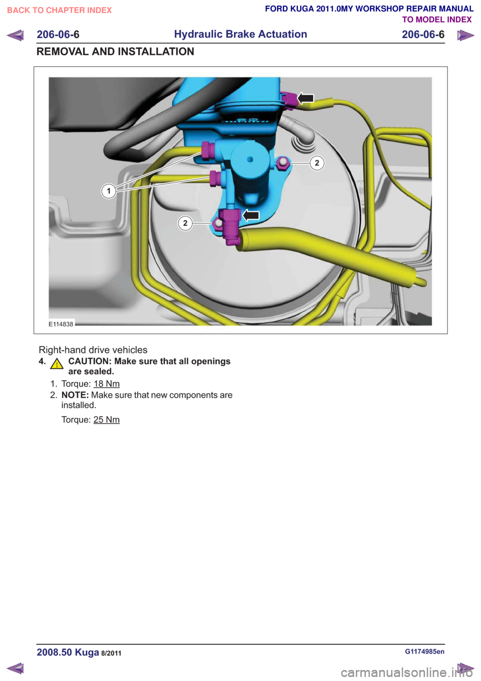
E114838
1
2
2
Right-hand drive vehicles
4. CAUTION: Make sure that all openingsare sealed.
1. Torque: 18Nm
2.NOTE: Make sure that new components are
installed.
Torque: 25
Nm
G1174985en2008.50 Kuga8/2011
206-06- 6
Hydraulic Brake Actuation
206-06- 6
REMOVAL AND INSTALLATION
TO MODEL INDEX
BACK TO CHAPTER INDEX
FORD KUGA 2011.0MY WORKSHOP REPAIR MANUAL
Page 1426 of 2057
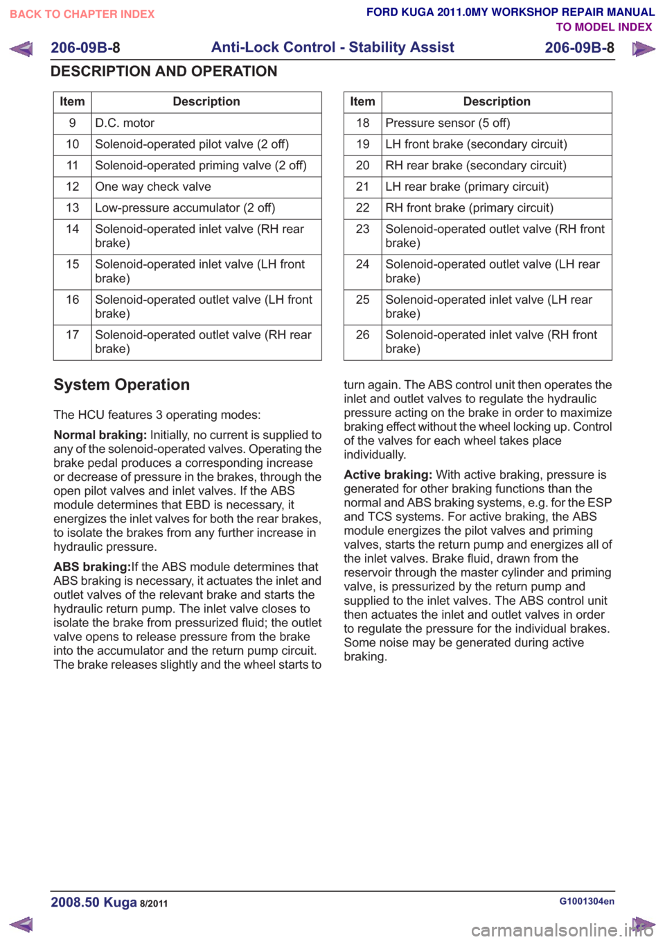
Description
Item
D.C. motor
9
Solenoid-operated pilot valve (2 off)
10
Solenoid-operated priming valve (2 off)
11
One way check valve
12
Low-pressure accumulator (2 off)
13
Solenoid-operated inlet valve (RH rear
brake)
14
Solenoid-operated inlet valve (LH front
brake)
15
Solenoid-operated outlet valve (LH front
brake)
16
Solenoid-operated outlet valve (RH rear
brake)
17Description
Item
Pressure sensor (5 off)
18
LH front brake (secondary circuit)
19
RH rear brake (secondary circuit)
20
LH rear brake (primary circuit)
21
RH front brake (primary circuit)
22
Solenoid-operated outlet valve (RH front
brake)
23
Solenoid-operated outlet valve (LH rear
brake)
24
Solenoid-operated inlet valve (LH rear
brake)
25
Solenoid-operated inlet valve (RH front
brake)
26
System Operation
The HCU features 3 operating modes:
Normal braking:
Initially, no current is supplied to
any of the solenoid-operated valves. Operating the
brake pedal produces a corresponding increase
or decrease of pressure in the brakes, through the
open pilot valves and inlet valves. If the ABS
module determines that EBD is necessary, it
energizes the inlet valves for both the rear brakes,
to isolate the brakes from any further increase in
hydraulic pressure.
ABS braking: If the ABS module determines that
ABS braking is necessary, it actuates the inlet and
outlet valves of the relevant brake and starts the
hydraulic return pump. The inlet valve closes to
isolate the brake from pressurized fluid; the outlet
valve opens to release pressure from the brake
into the accumulator and the return pump circuit.
The brake releases slightly and the wheel starts to turn again. The ABS control unit then operates the
inlet and outlet valves to regulate the hydraulic
pressure acting on the brake in order to maximize
braking effect without the wheel locking up. Control
of the valves for each wheel takes place
individually.
Active braking:
With active braking, pressure is
generated for other braking functions than the
normal and ABS braking systems, e.g. for the ESP
and TCS systems. For active braking, the ABS
module energizes the pilot valves and priming
valves, starts the return pump and energizes all of
the inlet valves. Brake fluid, drawn from the
reservoir through the master cylinder and priming
valve, is pressurized by the return pump and
supplied to the inlet valves. The ABS control unit
then actuates the inlet and outlet valves in order
to regulate the pressure for the individual brakes.
Some noise may be generated during active
braking.
G1001304en2008.50 Kuga8/2011
206-09B- 8
Anti-Lock Control - Stability Assist
206-09B- 8
DESCRIPTION AND OPERATION
TO MODEL INDEX
BACK TO CHAPTER INDEX
FORD KUGA 2011.0MY WORKSHOP REPAIR MANUAL
Page 1471 of 2057
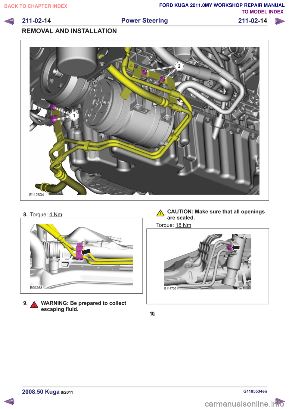
E112634
2
1
8.Torque: 4Nm
E99258
9. WARNING: Be prepared to collect
escaping fluid.
CAUTION: Make sure that all openings
are sealed.
Torque: 18
Nm
E114705
10.
G1185534en2008.50 Kuga8/2011
211-02- 14
Power Steering
211-02- 14
REMOVAL AND INSTALLATION
TO MODEL INDEX
BACK TO CHAPTER INDEX
FORD KUGA 2011.0MY WORKSHOP REPAIR MANUAL
Page 1479 of 2057
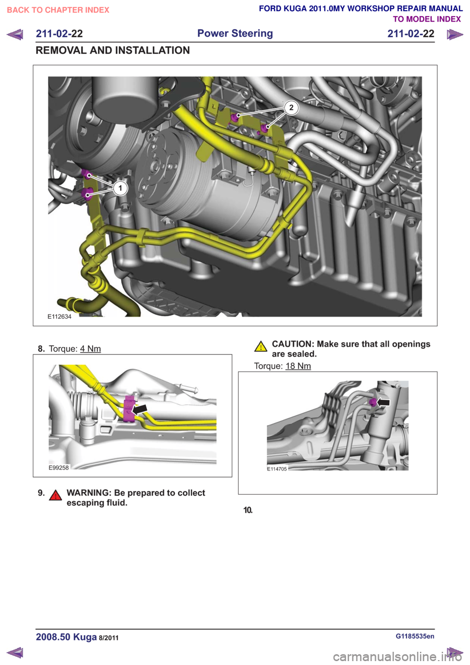
E112634
2
1
8.Torque: 4Nm
E99258
9. WARNING: Be prepared to collect
escaping fluid.
CAUTION: Make sure that all openings
are sealed.
Torque: 18
Nm
E114705
10.
G1185535en2008.50 Kuga8/2011
211-02- 22
Power Steering
211-02- 22
REMOVAL AND INSTALLATION
TO MODEL INDEX
BACK TO CHAPTER INDEX
FORD KUGA 2011.0MY WORKSHOP REPAIR MANUAL
Page 1484 of 2057
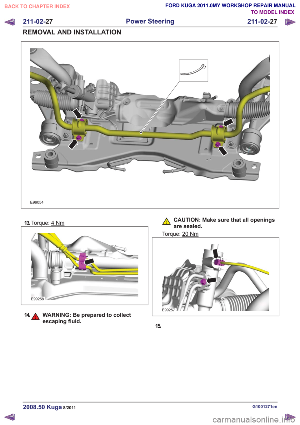
E99054
13.Torque: 4Nm
E99258
14. WARNING: Be prepared to collect
escaping fluid.
CAUTION: Make sure that all openings
are sealed.
Torque: 20
Nm
E99257
15.
G1001271en2008.50 Kuga8/2011
211-02- 27
Power Steering
211-02- 27
REMOVAL AND INSTALLATION
TO MODEL INDEX
BACK TO CHAPTER INDEX
FORD KUGA 2011.0MY WORKSHOP REPAIR MANUAL