rain sensor FORD KUGA 2011 1.G Service Manual
[x] Cancel search | Manufacturer: FORD, Model Year: 2011, Model line: KUGA, Model: FORD KUGA 2011 1.GPages: 2057
Page 1999 of 2057

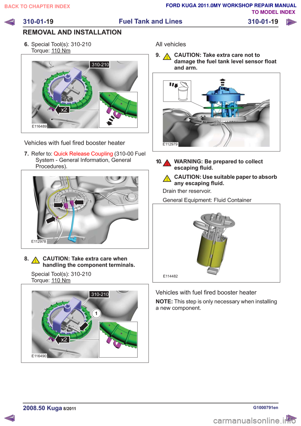
6.Special Tool(s): 310-210
Torque: 1
10Nm
310-210
x2
310-210
x2
E116489
Vehicles with fuel fired booster heater
7.Refer to: Quick Release Coupling (310-00 Fuel
System - General Information, General
Procedures).
E112978
8. CAUTION: Take extra care when handling the component terminals.
Special Tool(s): 310-210
Torque: 1
10Nm
310-210
x2
310-210
x2
E116490
1
All vehicles
9. CAUTION: Take extra care not todamage the fuel tank level sensor float
and arm.
E112979
10. WARNING: Be prepared to collectescaping fluid.
CAUTION: Use suitable paper to absorb
any escaping fluid.
Drain ther reservoir.
General Equipment: Fluid Container
E114482
Vehicles with fuel fired booster heater
NOTE: This step is only necessary when installing
a new component.
G1000791en2008.50 Kuga8/2011
310-01- 19
Fuel Tank and Lines
310-01- 19
REMOVAL AND INSTALLATION
TO MODEL INDEX
BACK TO CHAPTER INDEX
FORD KUGA 2011.0MY WORKSHOP REPAIR MANUAL
Page 2015 of 2057

• The refrigerant line between the fixed orificetube and the evaporator must be cold from the
point where the fixed orifice tube is installed.
Depending on the weather, the refrigerant line
may also have ice on its surface.
• The refrigerant line between the evaporator and the A/C compressor including the dehydrator
must be cold.
Evaporator outlet line temperature test
To test the power of the A/C system, the
temperature at the evaporator outlet line must be
measured. To do this, the following preconditions
must be met:
• Open all windows.
• Set the air distribution to the defrost/dashboardposition and open all the ventilation nozzles.
• DO NOT switch on recirculated air.
• Select lowest blower switch setting.
• Select lowest temperature setting.
NOTE: The temperature measurement cannot be
done with a thermometer which makes no contact.
The surface reflection from the metal line may
cause incorrect readings.
Connect the temperature sensor (Fluke 80 PK-8)
to the outlet line of the evaporator. Locate the
temperature sensor as close as possible to the
evaporator. Connect the temperature sensor to the
multimeter.
Start the engine and allow it to run at idle speed
for several minutes.
Switch on the A/C.
After three minutes, measure the surface
temperature of the evaporator outlet line.
If the temperature measured is 4° C or lower, the
A/C system is OK. If the temperature is higher, the
A/C system may be under-filled. For further
information, refer to
REFER to: Air Conditioning (A/C) System
Recovery, Evacuation and Charging (412-00
Climate Control System - General Information,
General Procedures).
Frequent faults and their causes
If the cooling power of the A/C system is not
adequate, make certain that the temperature
control flap(s) is/are operating correctly. • No or poor cooling performance:
– Blockage or narrowing of a refrigerant line orin the dehydrator. The location of the
blockage or narrowing can easily be located
by temperature comparisons at the
refrigerant lines and the dehydrator. The
blockage or restriction is located at the point
where the temperature difference is
identified. Note: A temperature difference
in the area of the fixed orifice tube is
normal. If the location of the blockage or
narrowing is found, check the corresponding
component and renew as applicable.
• Sudden drop in cooling performance (after the air conditioning has been switched off for
approx. 5 minutes, the cooling performance
returns to normal):
– The cause is an iced-up fixed orifice tubebecause of moisture in the refrigerant circuit.
In order to ensure that moisture is completely
removed from the refrigerant circuit, the
dehydrator should be renewed and the
evacuation time should be extended to 2-3
hours. For further information
REFER to: Air Conditioning (A/C) System
Recovery, Evacuation and Charging
(412-00 Climate Control System - General
Information, General Procedures).
Sequence of A/C Request Signal
NOTE: The electronic automatic temperature
control (EATC) module is integrated into the air
conditioning control assembly.
NOTE: The generic electronic module (GEM) is
an integral part of the central junction box (CJB).
After actuating the A/C ON/OFF switch integrated
into the A/C control assembly, an A/C request
signal is sent from the A/C control assembly
(vehicles with EATC: EATC module) to the GEM.
From there, the signal is sent to the instrument
cluster via the MS-CAN bus. A gateway is installed
in the instrument cluster, which establishes the
connection between the MS-CAN bus and the
HS-CAN bus.
After the signal has been converted in the gateway,
it is relayed to the powertrain control module (PCM)
via the HS-CAN bus. Once all the required
parameters have been met, the PCM switches on
the refrigerant compressor and thus the A/C system
via the A/C clutch relay.
G1055878en2008.50 Kuga8/2011
412-00- 4
Climate Control System - General Information
412-00- 4
DIAGNOSIS AND TESTING
TO MODEL INDEX
BACK TO CHAPTER INDEX
FORD KUGA 2011.0MY WORKSHOP REPAIR MANUAL
Page 2045 of 2057

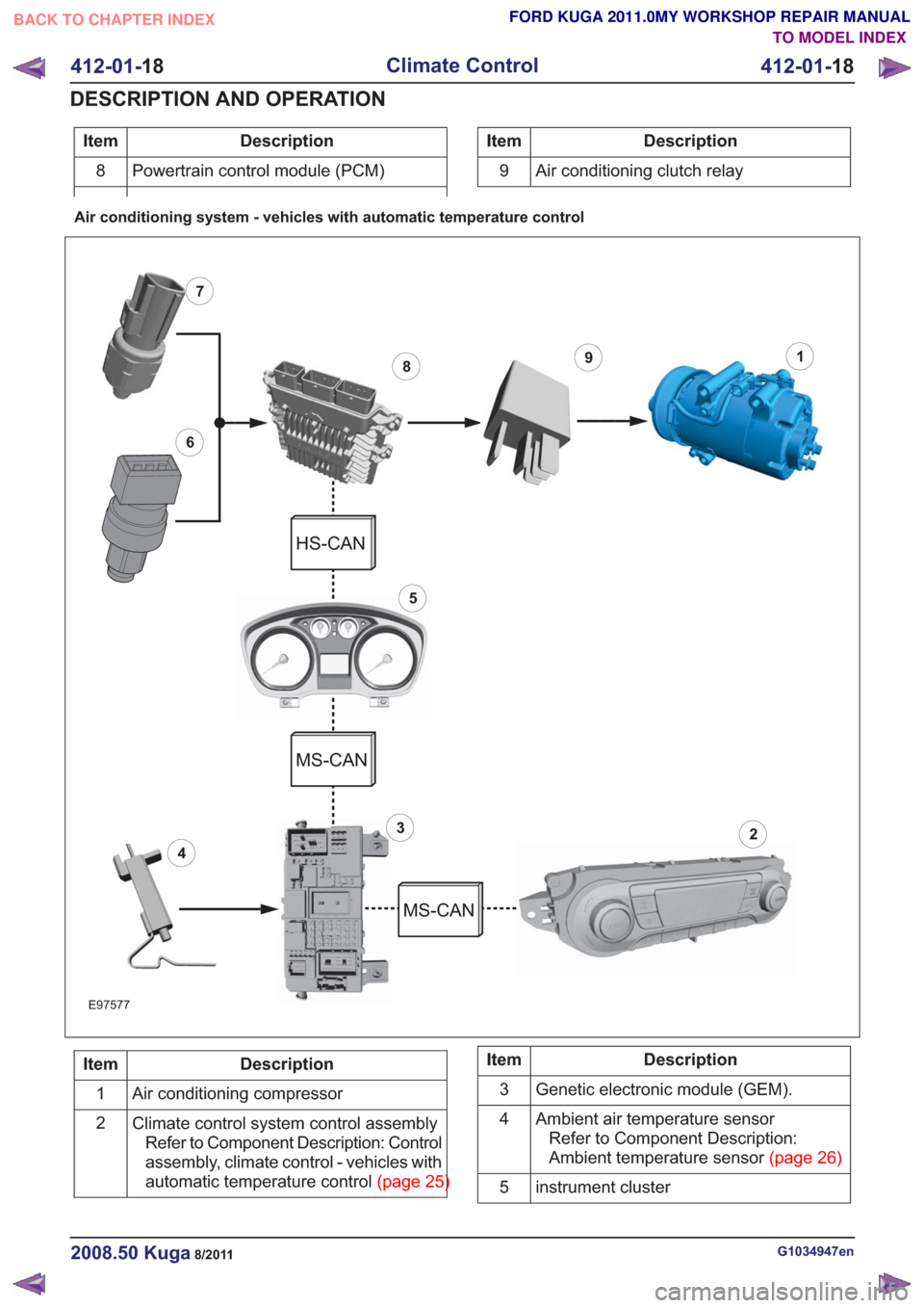
Description
Item
Powertrain control module (PCM)
8Description
Item
9 Air conditioning clutch relay
Air conditioning system - vehicles with automatic temperature control
18
6
7
3
9
5
2
4
E97577
HS-CAN
MS-CAN
MS-CAN
Description
Item
Air conditioning compressor
1
Climate control system control assemblyRefer to Component Description: Control
assembly, climate control - vehicles with
automatictemperaturecontrol(page25)
2Description
Item
Genetic electronic module (GEM).
3
Ambient air temperature sensorRefer to Component Description:
Ambienttemperaturesensor(page26)
4
instrument cluster
5
G1034947en2008.50 Kuga8/2011
412-01- 18
Climate Control
412-01- 18
DESCRIPTION AND OPERATION
TO MODEL INDEX
BACK TO CHAPTER INDEX
FORD KUGA 2011.0MY WORKSHOP REPAIR MANUAL