rain sensor FORD KUGA 2011 1.G Owner's Manual
[x] Cancel search | Manufacturer: FORD, Model Year: 2011, Model line: KUGA, Model: FORD KUGA 2011 1.GPages: 2057
Page 1703 of 2057
Action
Possible Sources
Symptom
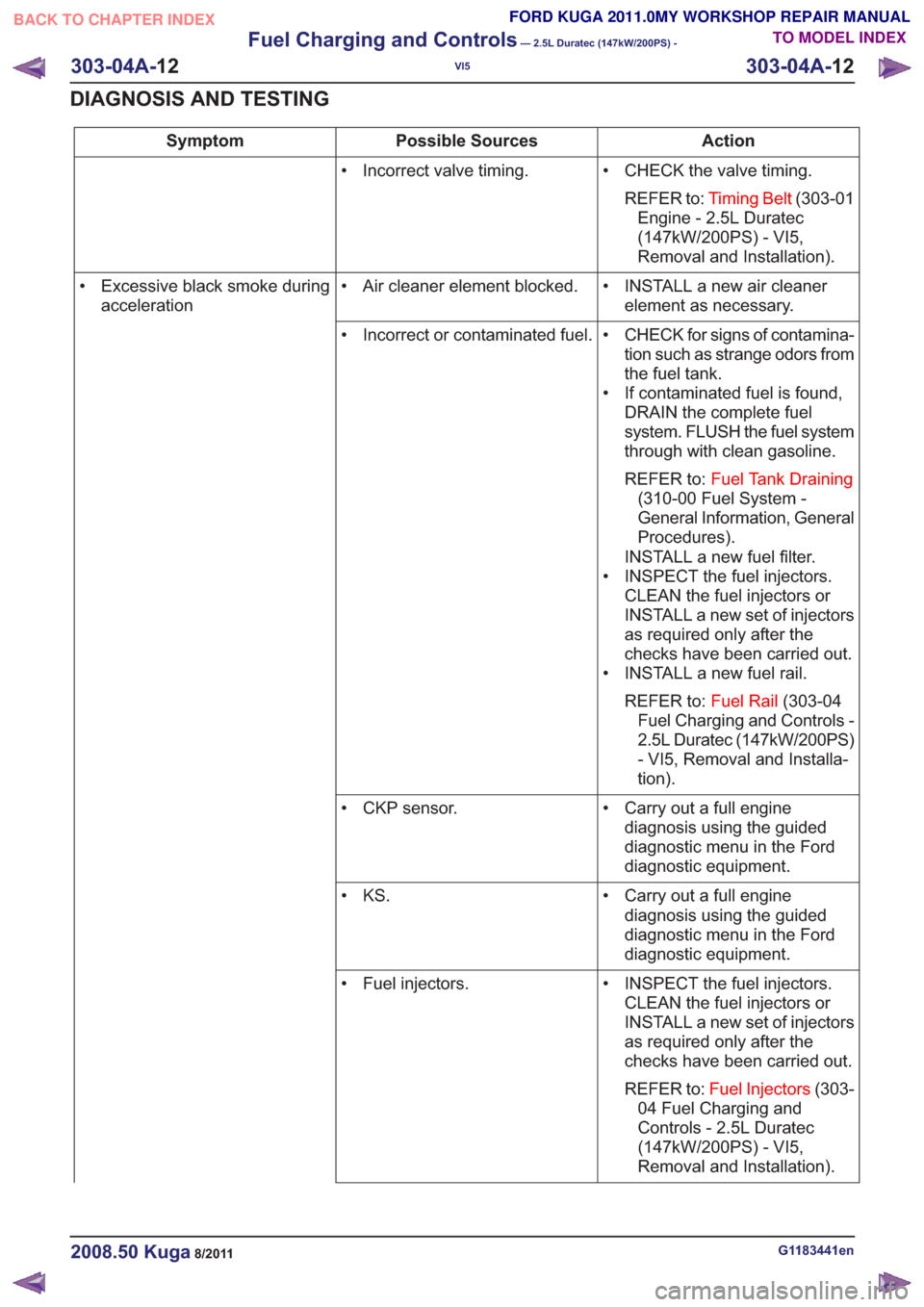
• CHECK the valve timing.REFER to: Timing Belt (303-01
Engine - 2.5L Duratec
(147kW/200PS) - VI5,
Removal and Installation).
• Incorrect valve timing.
• INSTALL a new air cleanerelement as necessary.
• Air cleaner element blocked.
• Excessive black smoke during
acceleration
• CHECK for signs of contamina-tion such as strange odors from
the fuel tank.
• If contaminated fuel is found, DRAIN the complete fuel
system. FLUSH the fuel system
through with clean gasoline.
REFER to: Fuel Tank Draining
(310-00 Fuel System -
General Information, General
Procedures).
INSTALL a new fuel filter.
• INSPECT the fuel injectors. CLEAN the fuel injectors or
INSTALL a new set of injectors
as required only after the
checks have been carried out.
• INSTALL a new fuel rail.
REFER to: Fuel Rail(303-04
Fuel Charging and Controls -
2.5L Duratec (147kW/200PS)
- VI5, Removal and Installa-
tion).
• Incorrect or contaminated fuel.
• Carry out a full enginediagnosis using the guided
diagnostic menu in the Ford
diagnostic equipment.
• CKP sensor.
• Carry out a full enginediagnosis using the guided
diagnostic menu in the Ford
diagnostic equipment.
• KS.
• INSPECT the fuel injectors.CLEAN the fuel injectors or
INSTALL a new set of injectors
as required only after the
checks have been carried out.
REFER to: Fuel Injectors (303-
04 Fuel Charging and
Controls - 2.5L Duratec
(147kW/200PS) - VI5,
Removal and Installation).
• Fuel injectors.
G1183441en2008.50 Kuga8/2011
303-04A-
12
Fuel Charging and Controls
— 2.5L Duratec (147kW/200PS) -
VI5
303-04A- 12
DIAGNOSIS AND TESTING
TO MODEL INDEX
BACK TO CHAPTER INDEX
FORD KUGA 2011.0MY WORKSHOP REPAIR MANUAL
Page 1707 of 2057
Action
Possible Sources
Symptom
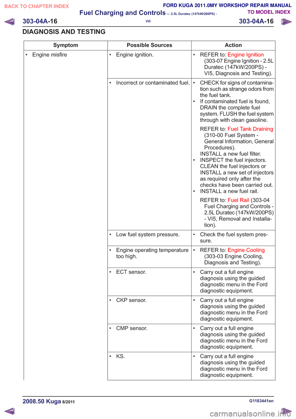
• REFER to:Engine Ignition
(303-07 Engine Ignition - 2.5L
Duratec (147kW/200PS) -
VI5, Diagnosis and Testing).
• Engine ignition.
• Engine misfire
• CHECK for signs of contamina-tion such as strange odors from
the fuel tank.
• If contaminated fuel is found, DRAIN the complete fuel
system. FLUSH the fuel system
through with clean gasoline.
REFER to: Fuel Tank Draining
(310-00 Fuel System -
General Information, General
Procedures).
INSTALL a new fuel filter.
• INSPECT the fuel injectors. CLEAN the fuel injectors or
INSTALL a new set of injectors
as required only after the
checks have been carried out.
• INSTALL a new fuel rail.
REFER to: Fuel Rail(303-04
Fuel Charging and Controls -
2.5L Duratec (147kW/200PS)
- VI5, Removal and Installa-
tion).
• Incorrect or contaminated fuel.
• Check the fuel system pres-sure.
• Low fuel system pressure.
• REFER to:Engine Cooling
(303-03 Engine Cooling,
Diagnosis and Testing).
• Engine operating temperature
too high.
• Carry out a full enginediagnosis using the guided
diagnostic menu in the Ford
diagnostic equipment.
• ECT sensor.
• Carry out a full enginediagnosis using the guided
diagnostic menu in the Ford
diagnostic equipment.
• CKP sensor.
• Carry out a full enginediagnosis using the guided
diagnostic menu in the Ford
diagnostic equipment.
• CMP sensor.
• Carry out a full enginediagnosis using the guided
diagnostic menu in the Ford
diagnostic equipment.
• KS.
G1183441en2008.50 Kuga8/2011
303-04A-
16
Fuel Charging and Controls
— 2.5L Duratec (147kW/200PS) -
VI5
303-04A- 16
DIAGNOSIS AND TESTING
TO MODEL INDEX
BACK TO CHAPTER INDEX
FORD KUGA 2011.0MY WORKSHOP REPAIR MANUAL
Page 1709 of 2057
Action
Possible Sources
Symptom
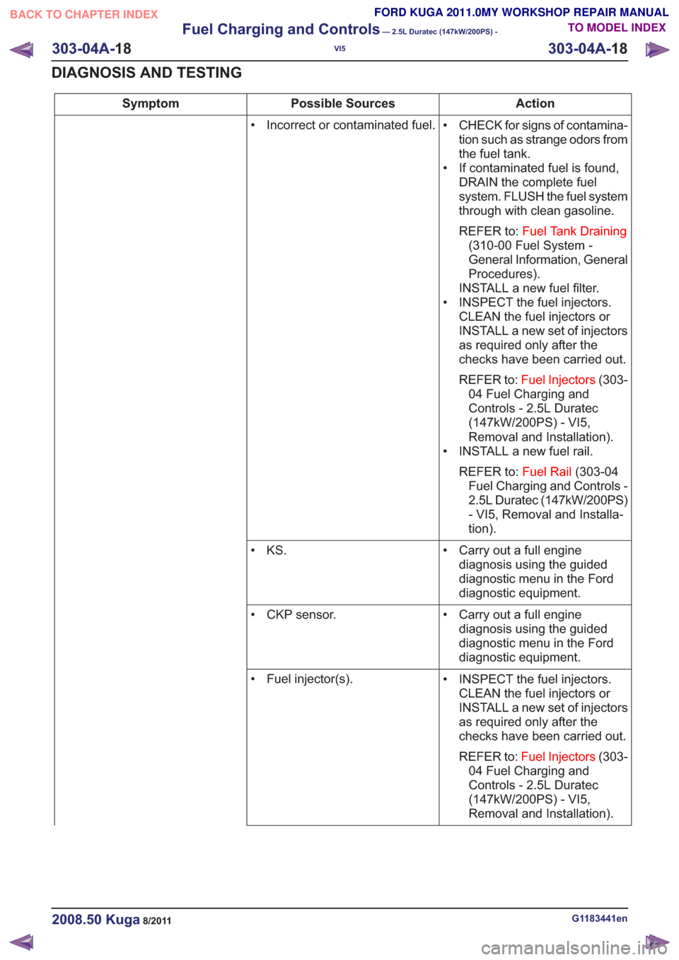
• CHECK for signs of contamina-tion such as strange odors from
the fuel tank.
• If contaminated fuel is found, DRAIN the complete fuel
system. FLUSH the fuel system
through with clean gasoline.
REFER to: Fuel Tank Draining
(310-00 Fuel System -
General Information, General
Procedures).
INSTALL a new fuel filter.
• INSPECT the fuel injectors. CLEAN the fuel injectors or
INSTALL a new set of injectors
as required only after the
checks have been carried out.
REFER to: Fuel Injectors (303-
04 Fuel Charging and
Controls - 2.5L Duratec
(147kW/200PS) - VI5,
Removal and Installation).
• INSTALL a new fuel rail.
REFER to: Fuel Rail(303-04
Fuel Charging and Controls -
2.5L Duratec (147kW/200PS)
- VI5, Removal and Installa-
tion).
• Incorrect or contaminated fuel.
• Carry out a full enginediagnosis using the guided
diagnostic menu in the Ford
diagnostic equipment.
• KS.
• Carry out a full enginediagnosis using the guided
diagnostic menu in the Ford
diagnostic equipment.
• CKP sensor.
• INSPECT the fuel injectors.CLEAN the fuel injectors or
INSTALL a new set of injectors
as required only after the
checks have been carried out.
REFER to: Fuel Injectors (303-
04 Fuel Charging and
Controls - 2.5L Duratec
(147kW/200PS) - VI5,
Removal and Installation).
• Fuel injector(s).
G1183441en2008.50 Kuga8/2011
303-04A-
18
Fuel Charging and Controls
— 2.5L Duratec (147kW/200PS) -
VI5
303-04A- 18
DIAGNOSIS AND TESTING
TO MODEL INDEX
BACK TO CHAPTER INDEX
FORD KUGA 2011.0MY WORKSHOP REPAIR MANUAL
Page 1722 of 2057
Description
Item
PWM (pulse width modulation) signal
Comments:from PCM (powertrain control module)
5
Atmospheric pressure
6
Turbocharger boost pressure.
7
from air filter
8
Intake air
9Description
Item
Recirculated air valveRefertoComponentDescription:(page
7)
10
Vacuum line, recirculated air valve
11
to intake manifold
12
Throttle plate
13
Compressor
14
Turbine
15
System Operation
Turbocharger(s)
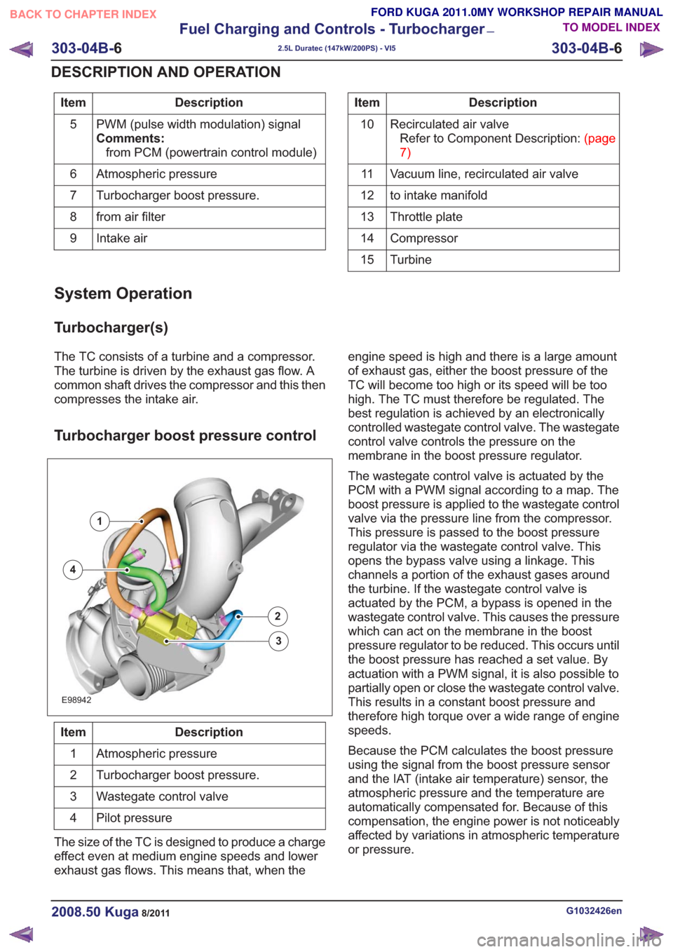
The TC consists of a turbine and a compressor.
The turbine is driven by the exhaust gas flow. A
common shaft drives the compressor and this then
compresses the intake air.
Turbocharger boost pressure control
E98942
1
2
3
4
Description
Item
Atmospheric pressure
1
Turbocharger boost pressure.
2
Wastegate control valve
3
Pilot pressure
4
The size of the TC is designed to produce a charge
effect even at medium engine speeds and lower
exhaust gas flows. This means that, when the engine speed is high and there is a large amount
of exhaust gas, either the boost pressure of the
TC will become too high or its speed will be too
high. The TC must therefore be regulated. The
best regulation is achieved by an electronically
controlled wastegate control valve. The wastegate
control valve controls the pressure on the
membrane in the boost pressure regulator.
The wastegate control valve is actuated by the
PCM with a PWM signal according to a map. The
boost pressure is applied to the wastegate control
valve via the pressure line from the compressor.
This pressure is passed to the boost pressure
regulator via the wastegate control valve. This
opens the bypass valve using a linkage. This
channels a portion of the exhaust gases around
the turbine. If the wastegate control valve is
actuated by the PCM, a bypass is opened in the
wastegate control valve. This causes the pressure
which can act on the membrane in the boost
pressure regulator to be reduced. This occurs until
the boost pressure has reached a set value. By
actuation with a PWM signal, it is also possible to
partially open or close the wastegate control valve.
This results in a constant boost pressure and
therefore high torque over a wide range of engine
speeds.
Because the PCM calculates the boost pressure
using the signal from the boost pressure sensor
and the IAT (intake air temperature) sensor, the
atmospheric pressure and the temperature are
automatically compensated for. Because of this
compensation, the engine power is not noticeably
affected by variations in atmospheric temperature
or pressure.
G1032426en2008.50 Kuga8/2011
303-04B-
6
Fuel Charging and Controls - Turbocharger
—
2.5L Duratec (147kW/200PS) - VI5
303-04B- 6
DESCRIPTION AND OPERATION
TO MODEL INDEX
BACK TO CHAPTER INDEX
FORD KUGA 2011.0MY WORKSHOP REPAIR MANUAL
Page 1767 of 2057
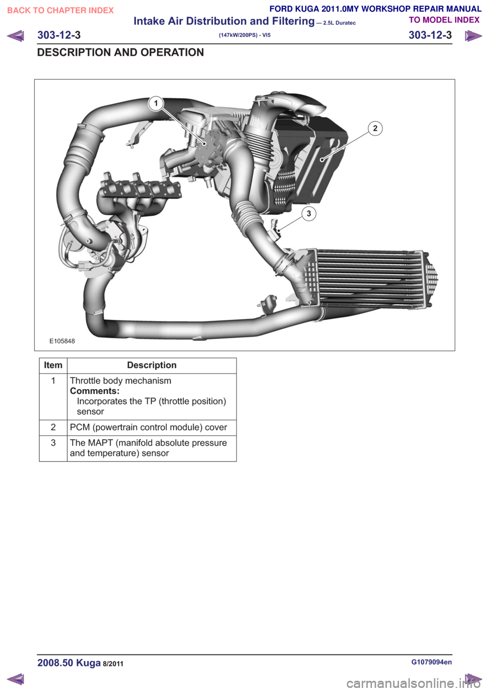
E105848
1
2
3
Description
Item
Throttle body mechanism
Comments:Incorporates the TP (throttle position)
sensor
1
PCM (powertrain control module) cover
2
The MAPT (manifold absolute pressure
and temperature) sensor
3
G1079094en2008.50 Kuga8/2011
303-12-
3
Intake Air Distribution and Filtering
— 2.5L Duratec
(147kW/200PS) - VI5
303-12- 3
DESCRIPTION AND OPERATION
TO MODEL INDEX
BACK TO CHAPTER INDEX
FORD KUGA 2011.0MY WORKSHOP REPAIR MANUAL
Page 1775 of 2057
SECTION 303-14 Electronic Engine Controls— 2.5L Duratec
(147kW/200PS) - VI5
VEHICLE APPLICATION: 2008.50 Kuga
PA G E
CONTENTS
DESCRIPTION AND OPERATION
303-14-3
Electronic Engine Controls (Component Location) .............................................................
303-14-7
Electronic Engine Controls (Overview) ........................................................................\
.......
303-14-7
General overview ........................................................................\
........................................
303-14-8
Powertrain Control Module (PCM) ........................................................................\
..............
303-14-8
Knock Sensor ........................................................................\
.............................................
303-14-8
Camshaft Position (CMP) Sensor ........................................................................\
...............
303-14-9
Crankshaft Position (CKP) sensor ........................................................................\
..............
303-14-9
Camshaft adjuster solenoid valve........................................................................\
...............
303-14-9
Manifold absolute pressure and temperature sensor .........................................................
303-14-9
Accelerator pedal position (APP) sensor ........................................................................\
....
303-14-10
Throttle control unit ........................................................................\
.....................................
303-14-10
Engine Coolant Temperature (ECT) sensor.......................................................................
303-14-10
Ignition coil-on-plug ........................................................................\
....................................
303-14-12
Electronic Engine Controls (System Operation and Component Description) ...................
303-14-12
System Diagram ........................................................................\
.........................................
303-14-16
System Operation ........................................................................\
.......................................
303-14-18
Speed and TDC recording ........................................................................\
......................
303-14-19
Calculation of the ignition angle ........................................................................\
..............
303-14-20
Engine fueling ........................................................................\
.........................................
303-14-22
Engine speed control ........................................................................\
..............................
303-14-22
Oil monitoring ........................................................................\
..........................................
303-14-23
Calculation of valve timing adjustment angle..................................................................
303-14-23
Boost pressure control ........................................................................\
............................
303-14-24
Starting process ........................................................................\
......................................
303-14-24
Alternator control (Smart Charge) ........................................................................\
...........
303-14-24
Component Description ........................................................................\
..............................
303-14-24
CKP sensor ........................................................................\
.............................................
303-14-25
Broadband HO2S ........................................................................\
...................................
303-14-26
VCT (variable camshaft timing) solenoids ......................................................................
303-14-27
MAF sensor ........................................................................\
.............................................
303-14-28
APP sensor ........................................................................\
.............................................
303-14-29
CPP sensor ........................................................................\
.............................................
303-14-29
BPP switches ........................................................................\
..........................................
303-14-30
Air conditioning (A/C) pressure sensor ........................................................................\
...
303-14-30
Throttle
control unit ........................................................................\
.................................
303-14-31
ECT sensor ........................................................................\
.............................................
303-14-31
Cooling fan module ........................................................................\
.................................
303-14-32
injectors........................................................................\
...................................................
303-14-32
Ignition coil-on-plug ........................................................................\
.................................
303-14-33
Fuel pressure/fuel temperature sensor ........................................................................\
...
303-14-33
Wastegate control valve ........................................................................\
..........................
303-14-34
Engine oil level, temperature and quality sensor ............................................................
303-14-1
Electronic Engine Controls— 2.5L Duratec (147kW/200PS) - VI5303-14-
1
.
TO MODEL INDEX
BACK TO CHAPTER INDEX
PAGE 1 OF 2
FORD KUGA 2011.0MY WORKSHOP REPAIR MANUAL
Page 1776 of 2057
303-14-34
Exterior aor temperature sensor ........................................................................\
.............
DIAGNOSIS AND TESTING 303-14-35
Electronic Engine Controls ........................................................................\
.........................
303-14-35
Inspection and Verification ........................................................................\
..........................
REMOVAL AND INSTALLATION 303-14-36
(29 232 0)
Camshaft Position (CMP) Sensor ...................................................................
303-14-37
(29 219 0)
Catalyst Monitor Sensor ........................................................................\
.........
303-14-38
(29 230 0)
Crankshaft Position (CKP) Sensor .................................................................
303-14-40
(29 220 0)
Heated Oxygen Sensor (HO2S) .....................................................................
303-14-41
(29 222 0)
Knock Sensor (KS) ........................................................................\
.................
303-14-42
(29 226 0)
Mass Air Flow (MAF) Sensor ........................................................................\
..
303-14-43
(29 200 0)
Powertrain Control Module (PCM) .................................................................
303-14-45
(29 233 0)
Variable Valve Timing (VVT) Oil Control Solenoid ..........................................
303-14-46
(33 502 0)
Brake Pedal Position (BPP) Switch ................................................................
303-14-47
(33 503 0)
Clutch Pedal Position (CPP) Switch ...............................................................
303-14-2
Electronic Engine Controls— 2.5L Duratec (147kW/200PS) - VI5303-14-
2
.
TO MODEL INDEX
BACK TO CHAPTER INDEX
PAGE 2 OF 2
FORD KUGA 2011.0MY WORKSHOP REPAIR MANUAL
Page 1778 of 2057
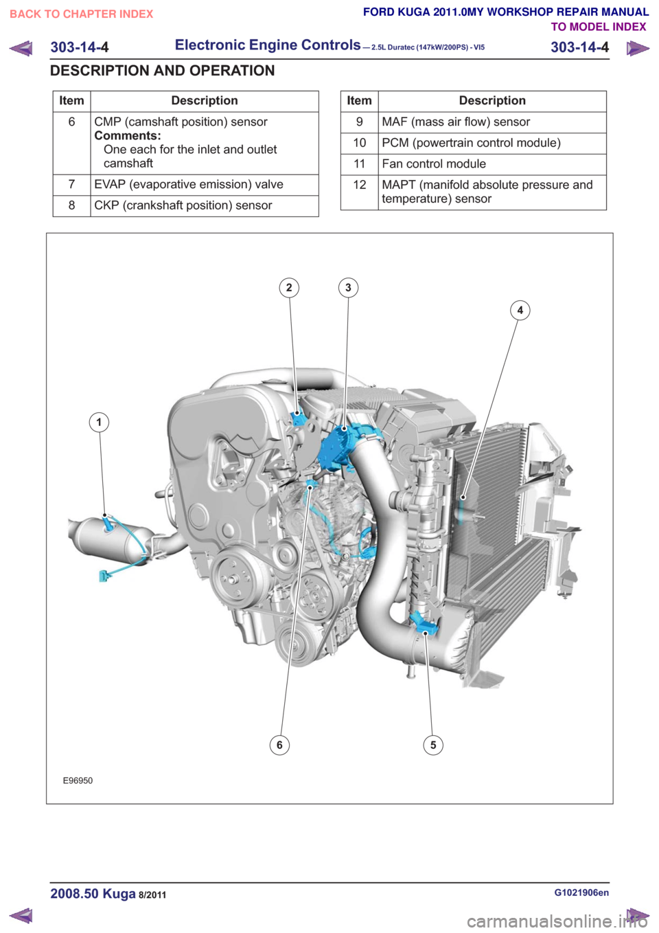
Description
Item
CMP (camshaft position) sensor
Comments:One each for the inlet and outlet
camshaft
6
EVAP (evaporative emission) valve
7
CKP (crankshaft position) sensor
8Description
Item
MAF (mass air flow) sensor
9
PCM (powertrain control module)
10
Fan control module
11
MAPT (manifold absolute pressure and
temperature) sensor
12
E96950
1
23
4
56
G1021906en2008.50 Kuga8/2011
303-14-
4
Electronic Engine Controls— 2.5L Duratec (147kW/200PS) - VI5303-14-
4
DESCRIPTION AND OPERATION
TO MODEL INDEX
BACK TO CHAPTER INDEX
FORD KUGA 2011.0MY WORKSHOP REPAIR MANUAL
Page 1782 of 2057
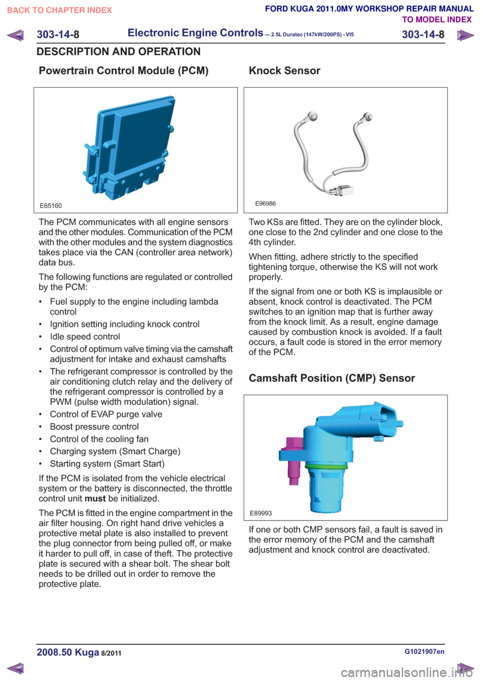
Powertrain Control Module (PCM)
E65160
The PCM communicates with all engine sensors
and the other modules. Communication of the PCM
with the other modules and the system diagnostics
takes place via the CAN (controller area network)
data bus.
The following functions are regulated or controlled
by the PCM:
• Fuel supply to the engine including lambdacontrol
• Ignition setting including knock control
• Idle speed control
• Control of optimum valve timing via the camshaft adjustment for intake and exhaust camshafts
• The refrigerant compressor is controlled by the air conditioning clutch relay and the delivery of
the refrigerant compressor is controlled by a
PWM (pulse width modulation) signal.
• Control of EVAP purge valve
• Boost pressure control
• Control of the cooling fan
• Charging system (Smart Charge)
• Starting system (Smart Start)
If the PCM is isolated from the vehicle electrical
system or the battery is disconnected, the throttle
control unit mustbe initialized.
The PCM is fitted in the engine compartment in the
air filter housing. On right hand drive vehicles a
protective metal plate is also installed to prevent
the plug connector from being pulled off, or make
it harder to pull off, in case of theft. The protective
plate is secured with a shear bolt. The shear bolt
needs to be drilled out in order to remove the
protective plate.
Knock Sensor
E96986
Two KSs are fitted. They are on the cylinder block,
one close to the 2nd cylinder and one close to the
4th cylinder.
When fitting, adhere strictly to the specified
tightening torque, otherwise the KS will not work
properly.
If the signal from one or both KS is implausible or
absent, knock control is deactivated. The PCM
switches to an ignition map that is further away
from the knock limit. As a result, engine damage
caused by combustion knock is avoided. If a fault
occurs, a fault code is stored in the error memory
of the PCM.
Camshaft Position (CMP) Sensor
E89993
If one or both CMP sensors fail, a fault is saved in
the error memory of the PCM and the camshaft
adjustment and knock control are deactivated.
G1021907en2008.50 Kuga8/2011
303-14- 8
Electronic Engine Controls— 2.5L Duratec (147kW/200PS) - VI5303-14-
8
DESCRIPTION AND OPERATION
TO MODEL INDEX
BACK TO CHAPTER INDEX
FORD KUGA 2011.0MY WORKSHOP REPAIR MANUAL
Page 1790 of 2057
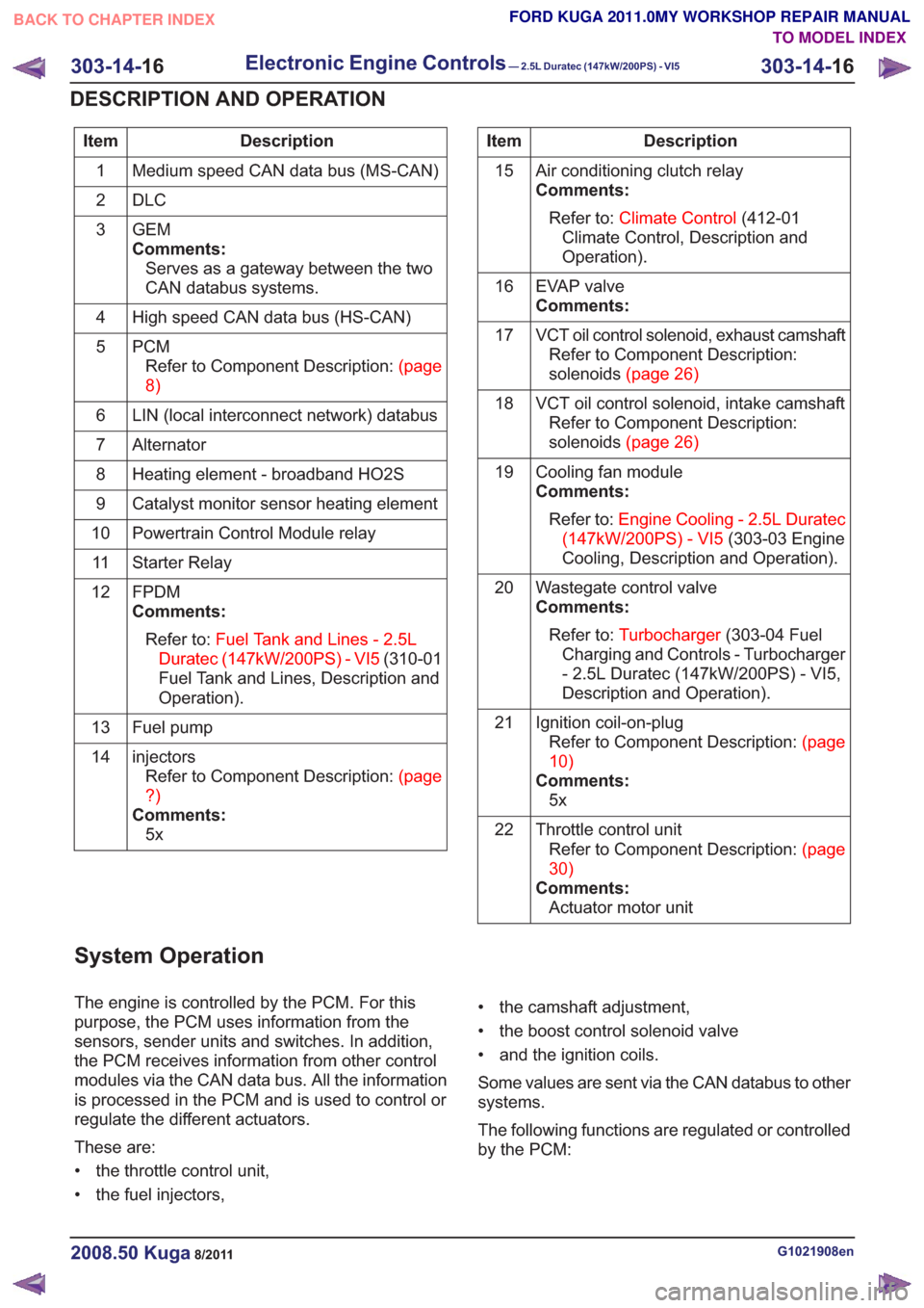
Description
Item
Medium speed CAN data bus (MS-CAN)
1
DLC
2
GEM
Comments:Serves as a gateway between the two
CAN databus systems.
3
High speed CAN data bus (HS-CAN)
4
PCMRefertoComponentDescription:(page
8)
5
LIN (local interconnect network) databus
6
Alternator
7
Heating element - broadband HO2S
8
Catalyst monitor sensor heating element
9
Powertrain Control Module relay
10
Starter Relay
11
FPDM
Comments:Refer to: Fuel Tank and Lines - 2.5L
Duratec (147kW/200PS) - VI5 (310-01
Fuel Tank and Lines, Description and
Operation).
12
Fuel pump
13
injectorsRefertoComponentDescription:(page
?)
Comments: 5x
14Description
Item
Air conditioning clutch relay
Comments:Refer to: Climate Control (412-01
Climate Control, Description and
Operation).
15
EVAP valve
Comments:
16
VCT oil control solenoid, exhaust camshaftRefer to Component Description:
solenoids(page26)
17
VCT oil control solenoid, intake camshaftRefer to Component Description:
solenoids(page26)
18
Cooling fan module
Comments:Refer to: Engine Cooling - 2.5L Duratec
(147kW/200PS) - VI5 (303-03 Engine
Cooling, Description and Operation).
19
Wastegate control valve
Comments:Refer to: Turbocharger (303-04 Fuel
Charging and Controls - Turbocharger
- 2.5L Duratec (147kW/200PS) - VI5,
Description and Operation).
20
Ignition coil-on-plugRefertoComponentDescription:(page
10)
Comments: 5x
21
Throttle control unitRefertoComponentDescription:(page
30)
Comments: Actuator motor unit
22
System Operation
The engine is controlled by the PCM. For this
purpose, the PCM uses information from the
sensors, sender units and switches. In addition,
the PCM receives information from other control
modules via the CAN data bus. All the information
is processed in the PCM and is used to control or
regulate the different actuators.
These are:
• the throttle control unit,
• the fuel injectors, • the camshaft adjustment,
• the boost control solenoid valve
• and the ignition coils.
Some values are sent via the CAN databus to other
systems.
The following functions are regulated or controlled
by the PCM:
G1021908en2008.50 Kuga8/2011
303-14-
16
Electronic Engine Controls— 2.5L Duratec (147kW/200PS) - VI5303-14-
16
DESCRIPTION AND OPERATION
TO MODEL INDEX
BACK TO CHAPTER INDEX
FORD KUGA 2011.0MY WORKSHOP REPAIR MANUAL