differential FORD KUGA 2011 1.G Repair Manual
[x] Cancel search | Manufacturer: FORD, Model Year: 2011, Model line: KUGA, Model: FORD KUGA 2011 1.GPages: 2057
Page 1295 of 2057
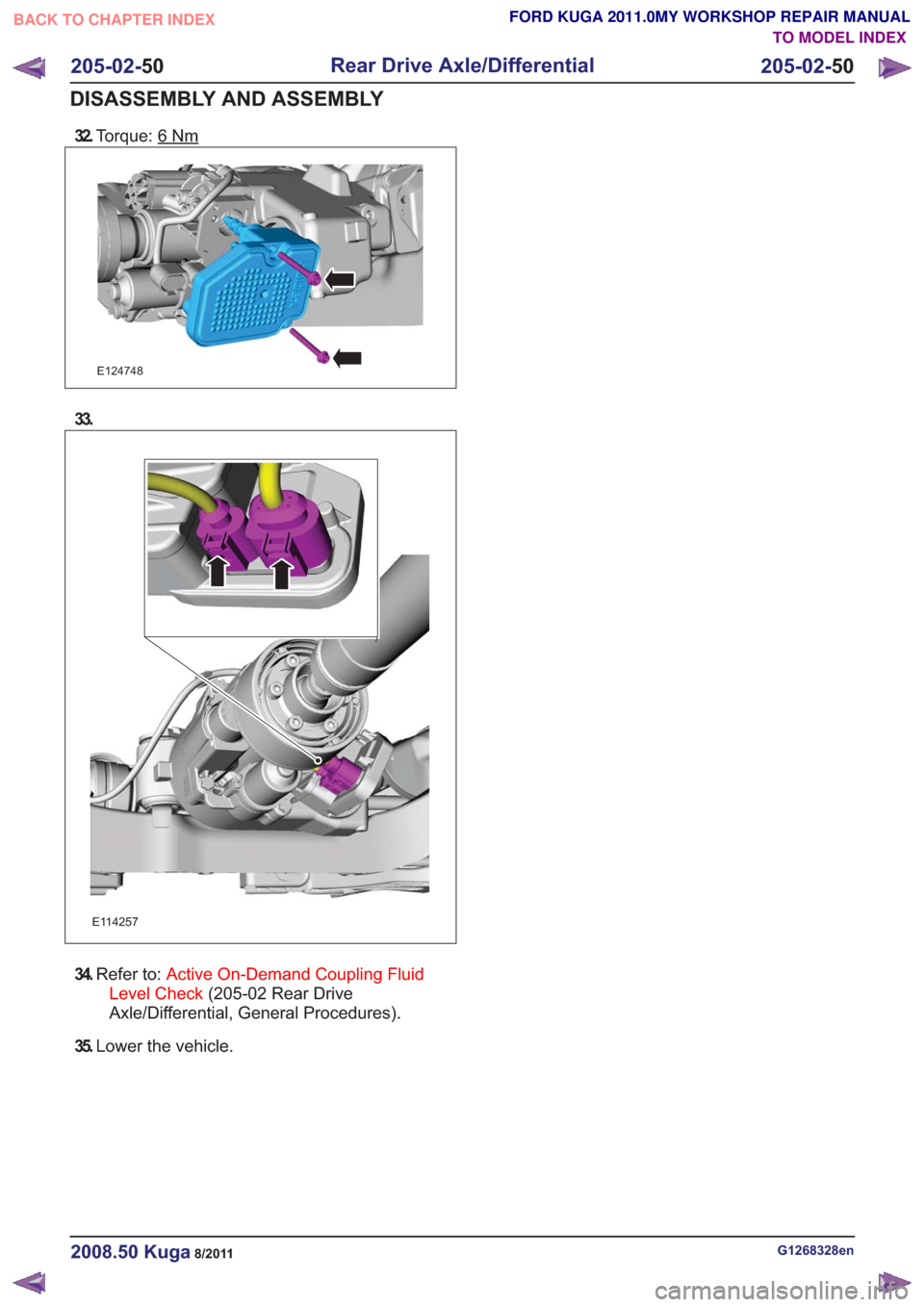
32.Torque: 6Nm
E124748
33.
E114257
34.Refer to: Active On-Demand Coupling Fluid
Level Check (205-02 Rear Drive
Axle/Differential, General Procedures).
35. Lower the vehicle.
G1268328en2008.50 Kuga8/2011
205-02- 50
Rear Drive Axle/Differential
205-02- 50
DISASSEMBLY AND ASSEMBLY
TO MODEL INDEX
BACK TO CHAPTER INDEX
FORD KUGA 2011.0MY WORKSHOP REPAIR MANUAL
Page 1299 of 2057
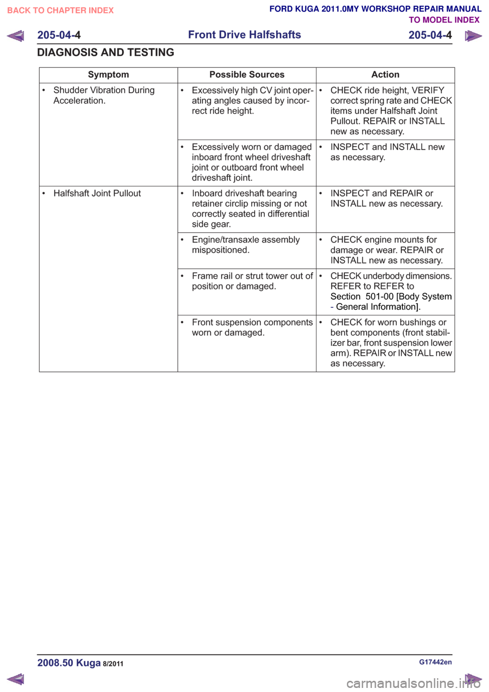
Action
Possible Sources
Symptom
• CHECK ride height, VERIFYcorrect spring rate and CHECK
items under Halfshaft Joint
Pullout. REPAIR or INSTALL
new as necessary.
• Excessively high CV joint oper-
ating angles caused by incor-
rect ride height.
• Shudder Vibration During
Acceleration.
• INSPECT and INSTALL newas necessary.
• Excessively worn or damaged
inboard front wheel driveshaft
joint or outboard front wheel
driveshaft joint.
• INSPECT and REPAIR orINSTALL new as necessary.
• Inboard driveshaft bearing
retainer circlip missing or not
correctly seated in differential
side gear.
• Halfshaft Joint Pullout
• CHECK engine mounts fordamage or wear. REPAIR or
INSTALL new as necessary.
• Engine/transaxle assembly
mispositioned.
• CHECK underbody dimensions.REFER to REFER to
Section 501-00 [Body System
-General Information] .
• Frame rail or strut tower out of
position or damaged.
• CHECK for worn bushings orbent components (front stabil-
izer bar, front suspension lower
arm). REPAIR or INSTALL new
as necessary.
• Front suspension components
worn or damaged.
G17442en2008.50 Kuga8/2011
205-04- 4
Front Drive Halfshafts
205-04- 4
DIAGNOSIS AND TESTING
TO MODEL INDEX
BACK TO CHAPTER INDEX
FORD KUGA 2011.0MY WORKSHOP REPAIR MANUAL
Page 1326 of 2057
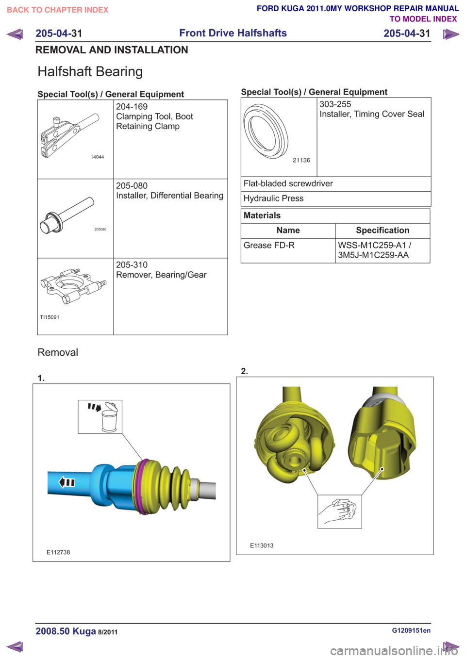
Halfshaft Bearing
Special Tool(s) / General Equipment204-169
Clamping Tool, Boot
Retaining Clamp
14044
205-080
Installer, Differential Bearing
205080
205-310
Remover, Bearing/Gear
TI15091
Special Tool(s) / General Equipment303-255
Installer, Timing Cover Seal
21136
Flat-bladed screwdriver
Hydraulic Press
Materials
Specification
Name
WSS-M1C259-A1 /
3M5J-M1C259-AA
Grease FD-R
Removal
1.
E112738
2.
E113013
G1209151en2008.50 Kuga8/2011
205-04-
31
Front Drive Halfshafts
205-04- 31
REMOVAL AND INSTALLATION
TO MODEL INDEX
BACK TO CHAPTER INDEX
FORD KUGA 2011.0MY WORKSHOP REPAIR MANUAL
Page 1336 of 2057

15.On both sides.
Refer to: Wheel and Tire (204-04 Wheels and
Tires, Removal and Installation).
16. Refer to: Differential Fluid Level Check (205-02
Rear Drive Axle/Differential, General
Procedures).
G1058429en2008.50 Kuga8/2011
205-05- 8
Rear Drive Halfshafts
205-05- 8
REMOVAL AND INSTALLATION
TO MODEL INDEX
BACK TO CHAPTER INDEX
FORD KUGA 2011.0MY WORKSHOP REPAIR MANUAL
Page 1825 of 2057
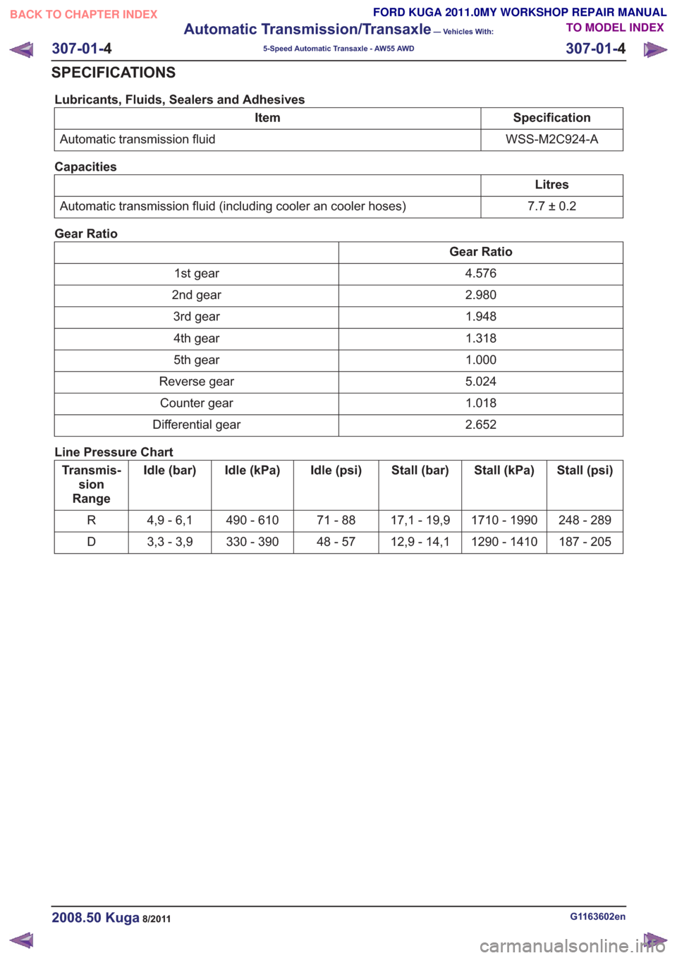
Lubricants, Fluids, Sealers and Adhesives
Specification
Item
WSS-M2C924-A
Automatic transmission fluid
Capacities
Litres
7.7±0.2
Automatic transmission fluid (including cooler an cooler hoses)
Gear Ratio
Gear Ratio 4.576
1st gear
2.980
2nd gear
1.948
3rd gear
1.318
4th gear
1.000
5th gear
5.024
Reverse gear
1.018
Counter gear
2.652
Differential gear
Line Pressure Chart
Stall (psi)
Stall (kPa)
Stall (bar)
Idle (psi)
Idle (kPa)
Idle (bar)
Transmis-
sion
Range
248 - 289
1710 - 1990
17,1 - 19,9
71 - 88
490 - 610
4,9 - 6,1
R
187 - 205
1290 - 1410
12,9 - 14,1
48 - 57
330 - 390
3,3 - 3,9
D
G1163602en2008.50 Kuga8/2011
307-01- 4
Automatic Transmission/Transaxle
— Vehicles With:
5-Speed Automatic Transaxle - AW55 AWD
307-01- 4
SPECIFICATIONS
TO MODEL INDEX
BACK TO CHAPTER INDEX
FORD KUGA 2011.0MY WORKSHOP REPAIR MANUAL
Page 1827 of 2057
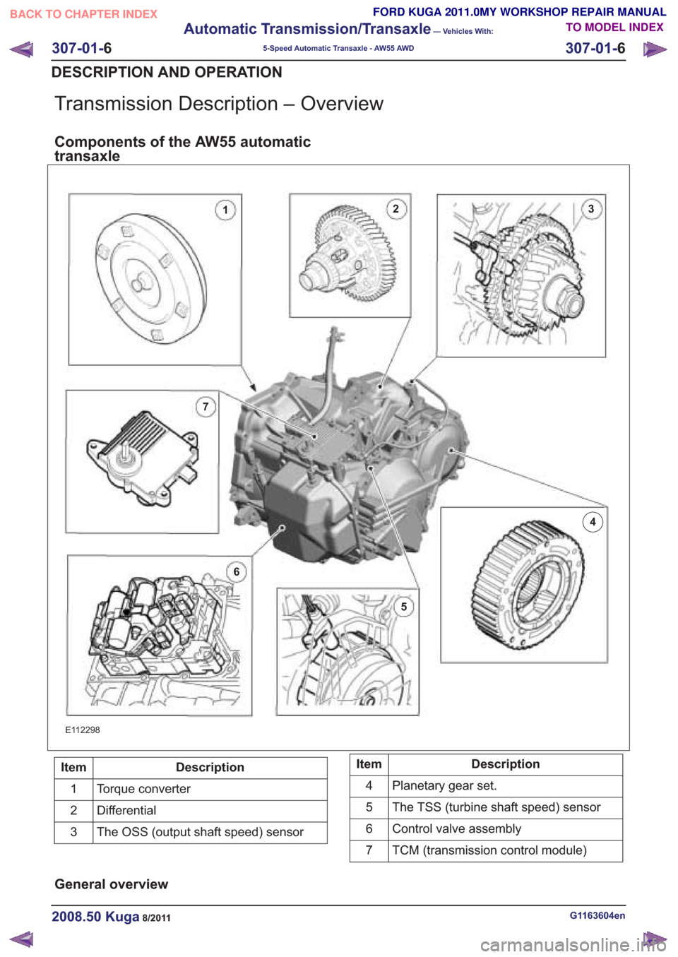
Transmission Description – Overview
Components of the AW55 automatic
transaxle
E112298
Description
Item
Torque converter
1
Differential
2
The OSS (output shaft speed) sensor
3Description
Item
Planetary gear set.
4
The TSS (turbine shaft speed) sensor
5
Control valve assembly
6
TCM (transmission control module)
7
General overview
G1163604en2008.50 Kuga8/2011
307-01- 6
Automatic Transmission/Transaxle
— Vehicles With:
5-Speed Automatic Transaxle - AW55 AWD
307-01- 6
DESCRIPTION AND OPERATION
TO MODEL INDEX
BACK TO CHAPTER INDEX
FORD KUGA 2011.0MY WORKSHOP REPAIR MANUAL
23
4
5
6
7
1
Page 1828 of 2057
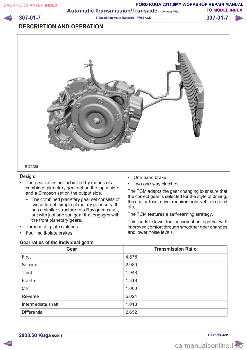
E125525
Design:
• The gear ratios are achieved by means of acombined planetary gear set on the input side
and a Simpson set on the output side.
– The combined planetary gear set consists oftwo different, simple planetary gear sets. It
has a similar structure to a Ravigneaux set,
but with just one sun gear that engages with
the front planetary gears.
• Three multi-plate clutches
• Four multi-plate brakes • One band brake
• Two one-way clutches
The TCM adapts the gear changing to ensure that
the correct gear is selected for the style of driving,
the engine load, driver requirements, vehicle speed
etc.
The TCM features a self-learning strategy.
This leads to lower fuel consumption together with
improved comfort through smoother gear changes
and lower noise levels.
Gear ratios of the individual gears
Transmission Ratio
Gear
4.576
First
2.980
Second
1.948
Third
1.318
Fourth
1.000
5th
5.024
Reverse
1.018
Intermediate shaft
2.652
Differential
G1163604en2008.50 Kuga8/2011
307-01- 7
Automatic Transmission/Transaxle
— Vehicles With:
5-Speed Automatic Transaxle - AW55 AWD
307-01- 7
DESCRIPTION AND OPERATION
TO MODEL INDEX
BACK TO CHAPTER INDEX
FORD KUGA 2011.0MY WORKSHOP REPAIR MANUAL
Page 1865 of 2057
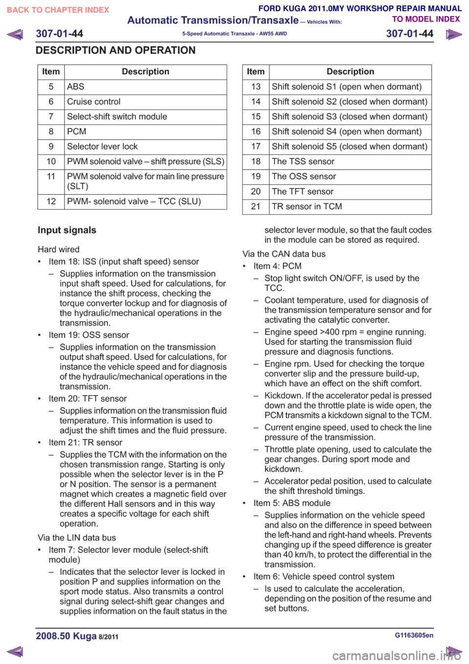
Description
Item
ABS5
Cruise control
6
Select-shift switch module
7
PCM
8
Selector lever lock
9
PWM solenoid valve – shift pressure (SLS)
10
PWM solenoid valve for main line pressure
(SLT)
11
PWM- solenoid valve – TCC (SLU)
12Description
Item
Shift solenoid S1 (open when dormant)
13
Shift solenoid S2 (closed when dormant)
14
Shift solenoid S3 (closed when dormant)
15
Shift solenoid S4 (open when dormant)
16
Shift solenoid S5 (closed when dormant)
17
The TSS sensor
18
The OSS sensor
19
The TFT sensor
20
TR sensor in TCM
21
Input signals
Hard wired
• Item 18: ISS (input shaft speed) sensor
– Supplies information on the transmissioninput shaft speed. Used for calculations, for
instance the shift process, checking the
torque converter lockup and for diagnosis of
the hydraulic/mechanical operations in the
transmission.
• Item 19: OSS sensor – Supplies information on the transmissionoutput shaft speed. Used for calculations, for
instance the vehicle speed and for diagnosis
of the hydraulic/mechanical operations in the
transmission.
• Item 20: TFT sensor – Supplies information on the transmission fluidtemperature. This information is used to
adjust the shift times and the fluid pressure.
• Item 21: TR sensor – Supplies the TCM with the information on thechosen transmission range. Starting is only
possible when the selector lever is in the P
or N position. The sensor is a permanent
magnet which creates a magnetic field over
the different Hall sensors and in this way
creates a specific voltage for each shift
operation.
Via the LIN data bus
• Item 7: Selector lever module (select-shift module)
– Indicates that the selector lever is locked inposition P and supplies information on the
sport mode status. Also transmits a control
signal during select-shift gear changes and
supplies information on the fault status in the selector lever module, so that the fault codes
in the module can be stored as required.
Via the CAN data bus
• Item 4: PCM – Stop light switch ON/OFF, is used by theTCC.
– Coolant temperature, used for diagnosis of the transmission temperature sensor and for
activating the catalytic converter.
– Engine speed >400 rpm = engine running. Used for starting the transmission fluid
pressure and diagnosis functions.
– Engine rpm. Used for checking the torque converter slip and the pressure build-up,
which have an effect on the shift comfort.
– Kickdown. If the accelerator pedal is pressed down and the throttle plate is wide open, the
PCM transmits a kickdown signal to the TCM.
– Current engine speed, used to check the line pressure of the transmission.
– Throttle plate opening, used to calculate the gear changes. During sport mode and
kickdown.
– Accelerator pedal position, used to calculate the shift threshold timings.
• Item 5: ABS module – Supplies information on the vehicle speedand also on the difference in speed between
the left-hand and right-hand wheels. Prevents
changing up if the speed difference is greater
than 40 km/h, to protect the differential in the
transmission.
• Item 6: Vehicle speed control system – Is used to calculate the acceleration,depending on the position of the resume and
set buttons.
G1163605en2008.50 Kuga8/2011
307-01- 44
Automatic Transmission/Transaxle
— Vehicles With:
5-Speed Automatic Transaxle - AW55 AWD
307-01- 44
DESCRIPTION AND OPERATION
TO MODEL INDEX
BACK TO CHAPTER INDEX
FORD KUGA 2011.0MY WORKSHOP REPAIR MANUAL
Page 1888 of 2057
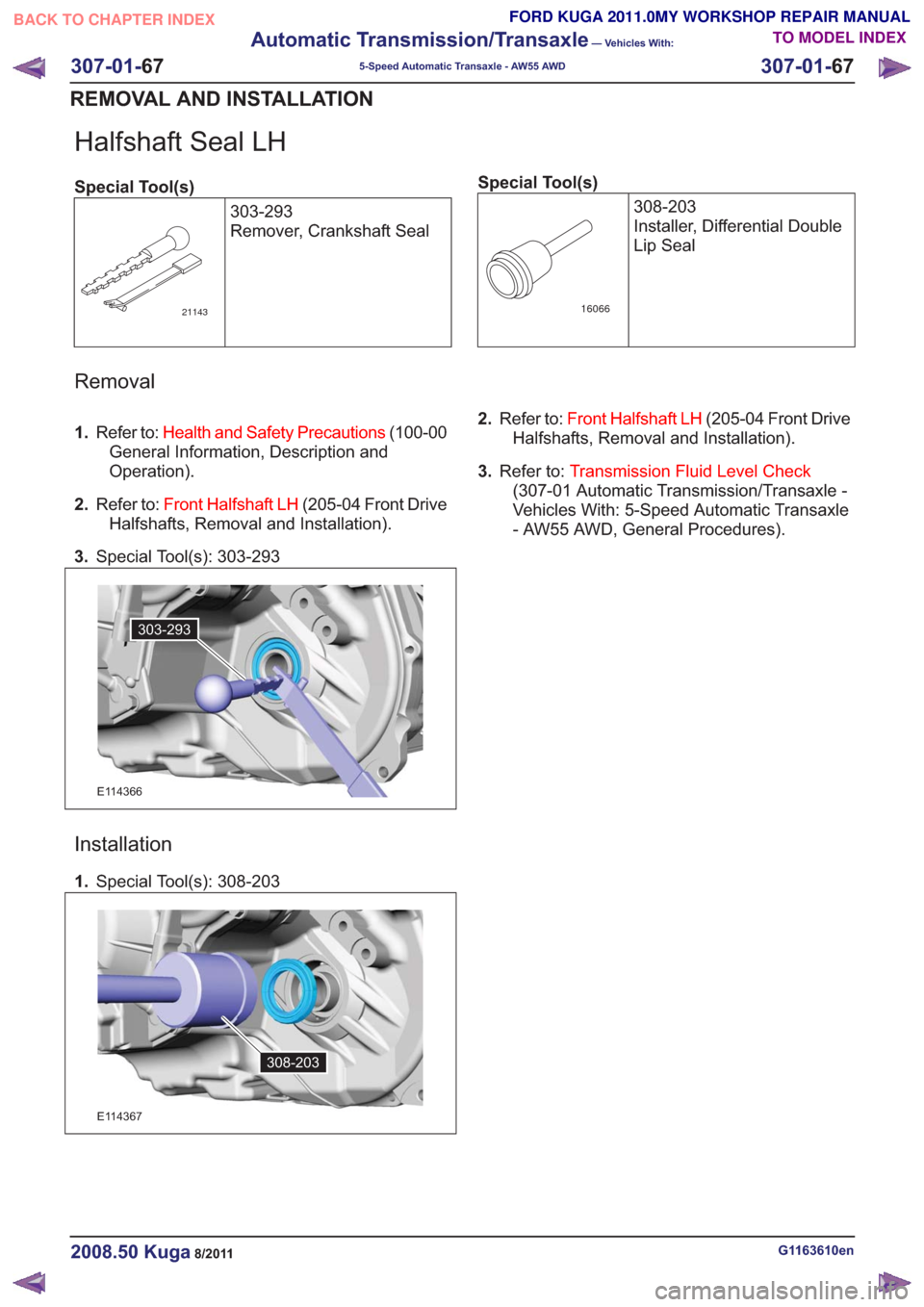
Halfshaft Seal LH
Special Tool(s)303-293
Remover, Crankshaft Seal
21143
Special Tool(s)308-203
Installer, Differential Double
Lip Seal
16066
Removal
1.Refer to: Health and Safety Precautions (100-00
General Information, Description and
Operation).
2. Refer to: Front Halfshaft LH (205-04 Front Drive
Halfshafts, Removal and Installation).
3. Special Tool(s): 303-293
303-293303-293
E114366
Installation
1.Special Tool(s): 308-203
308-203308-203
E114367
2.Refer to: Front Halfshaft LH (205-04 Front Drive
Halfshafts, Removal and Installation).
3. Refer to: Transmission Fluid Level Check
(307-01 Automatic Transmission/Transaxle -
Vehicles With: 5-Speed Automatic Transaxle
- AW55 AWD, General Procedures).
G1163610en2008.50 Kuga8/2011
307-01- 67
Automatic Transmission/Transaxle
— Vehicles With:
5-Speed Automatic Transaxle - AW55 AWD
307-01- 67
REMOVAL AND INSTALLATION
TO MODEL INDEX
BACK TO CHAPTER INDEX
FORD KUGA 2011.0MY WORKSHOP REPAIR MANUAL
Page 1945 of 2057
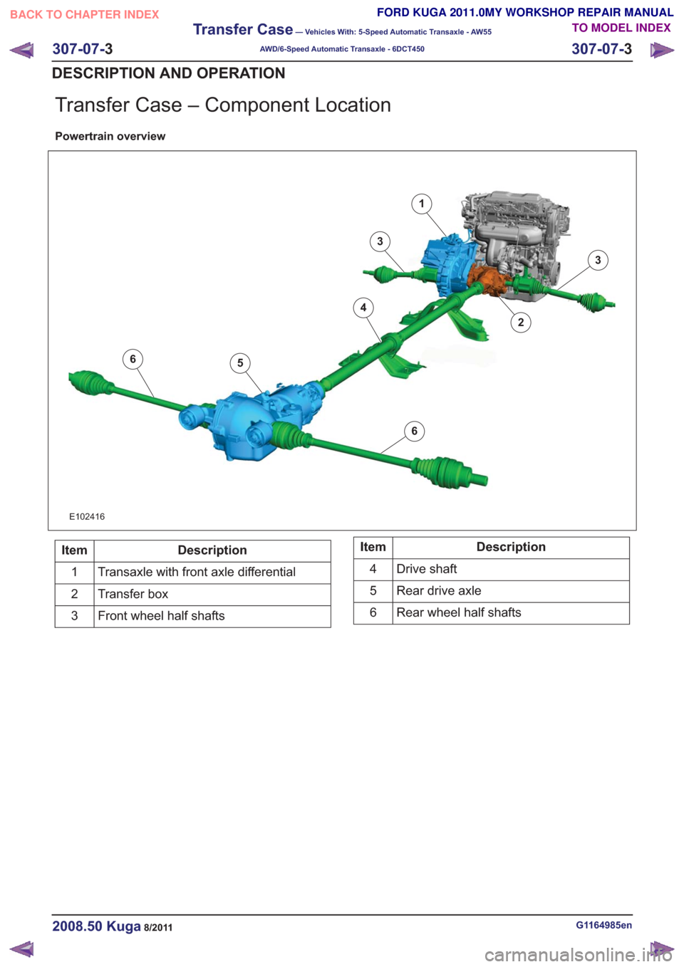
Transfer Case – Component Location
Powertrain overview
6
6
1
2
3
3
4
5
6
6
E102416
Description
Item
Transaxle with front axle differential
1
Transfer box
2
Front wheel half shafts
3Description
Item
Drive shaft
4
Rear drive axle
5
Rear wheel half shafts
6
G1164985en2008.50 Kuga8/2011
307-07- 3
Transfer Case
— Vehicles With: 5-Speed Automatic Transaxle - AW55
AWD/6-Speed Automatic Transaxle - 6DCT450
307-07- 3
DESCRIPTION AND OPERATION
TO MODEL INDEX
BACK TO CHAPTER INDEX
FORD KUGA 2011.0MY WORKSHOP REPAIR MANUAL