sensor FORD KUGA 2011 1.G Manual PDF
[x] Cancel search | Manufacturer: FORD, Model Year: 2011, Model line: KUGA, Model: FORD KUGA 2011 1.GPages: 2057
Page 1432 of 2057
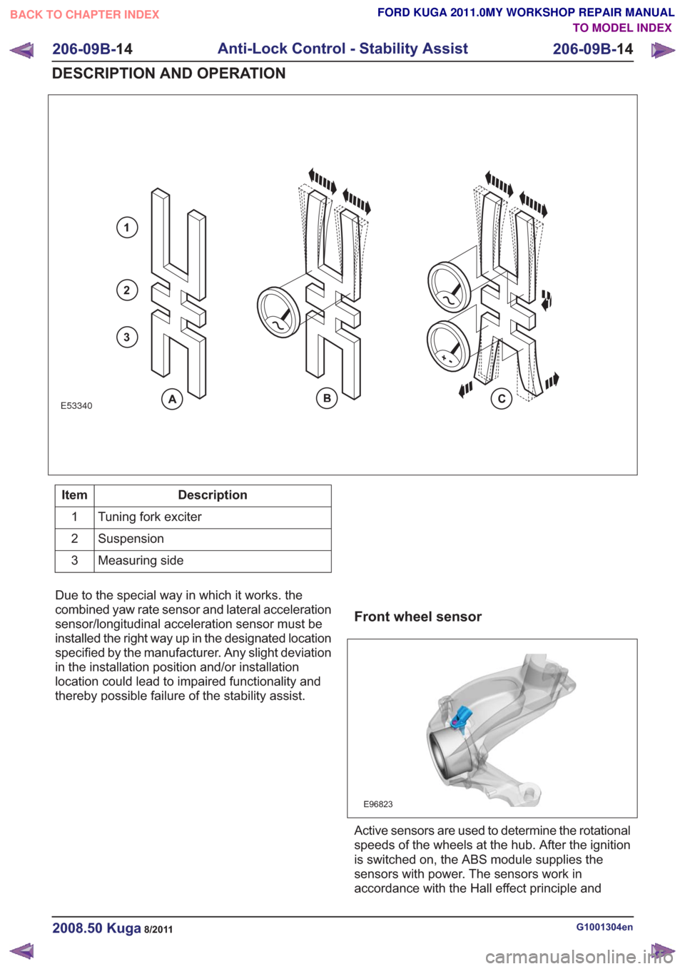
E53340
1
2
3
Description
Item
Tuning fork exciter
1
Suspension
2
Measuring side
3
Due to the special way in which it works. the
combined yaw rate sensor and lateral acceleration
sensor/longitudinal acceleration sensor must be
installed the right way up in the designated location
specified by the manufacturer. Any slight deviation
in the installation position and/or installation
location could lead to impaired functionality and
thereby possible failure of the stability assist.
Front wheel sensor
E96823
Active sensors are used to determine the rotational
speeds of the wheels at the hub. After the ignition
is switched on, the ABS module supplies the
sensors with power. The sensors work in
accordance with the Hall effect principle and
G1001304en2008.50 Kuga8/2011
206-09B- 14
Anti-Lock Control - Stability Assist
206-09B- 14
DESCRIPTION AND OPERATION
TO MODEL INDEX
BACK TO CHAPTER INDEX
FORD KUGA 2011.0MY WORKSHOP REPAIR MANUAL
Page 1433 of 2057
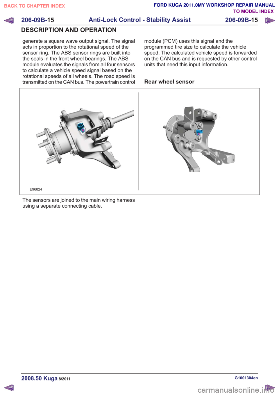
generate a square wave output signal. The signal
acts in proportion to the rotational speed of the
sensor ring. The ABS sensor rings are built into
the seals in the front wheel bearings. The ABS
module evaluates the signals from all four sensors
to calculate a vehicle speed signal based on the
rotational speeds of all wheels. The road speed is
transmitted on the CAN bus. The powertrain controlmodule (PCM) uses this signal and the
programmed tire size to calculate the vehicle
speed. The calculated vehicle speed is forwarded
on the CAN bus and is requested by other control
units that need this input information.
Rear wheel sensor
E96824
The sensors are joined to the main wiring harness
using a separate connecting cable.
G1001304en2008.50 Kuga8/2011
206-09B-
15
Anti-Lock Control - Stability Assist
206-09B- 15
DESCRIPTION AND OPERATION
TO MODEL INDEX
BACK TO CHAPTER INDEX
FORD KUGA 2011.0MY WORKSHOP REPAIR MANUAL
Page 1439 of 2057
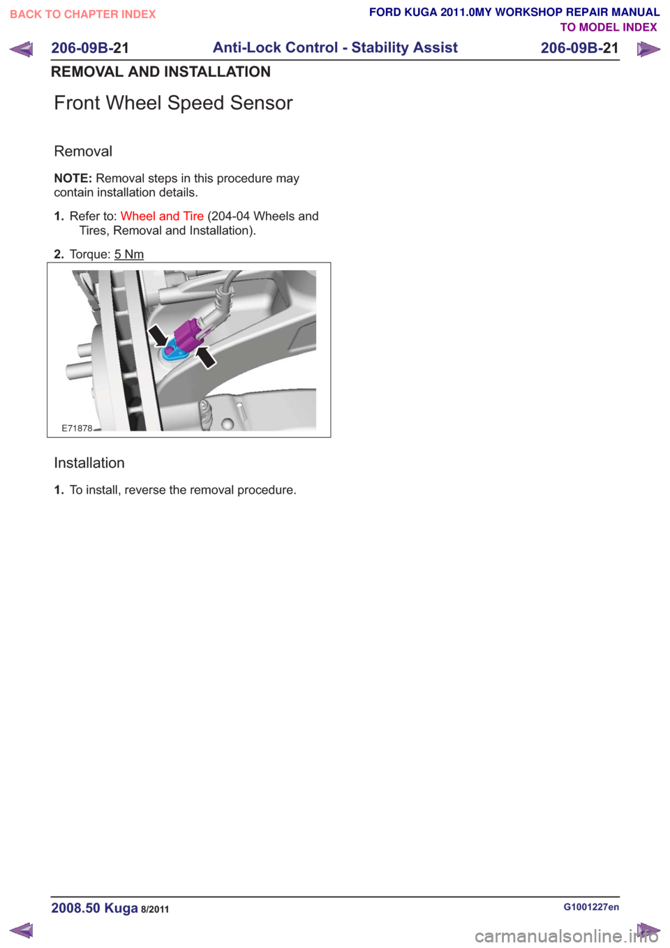
Front Wheel Speed Sensor
Removal
NOTE:Removal steps in this procedure may
contain installation details.
1. Refer to: Wheel and Tire (204-04 Wheels and
Tires, Removal and Installation).
2. Torque: 5
Nm
E71878
Installation
1.To install, reverse the removal procedure.
G1001227en2008.50 Kuga8/2011
206-09B- 21
Anti-Lock Control - Stability Assist
206-09B- 21
REMOVAL AND INSTALLATION
TO MODEL INDEX
BACK TO CHAPTER INDEX
FORD KUGA 2011.0MY WORKSHOP REPAIR MANUAL
Page 1440 of 2057
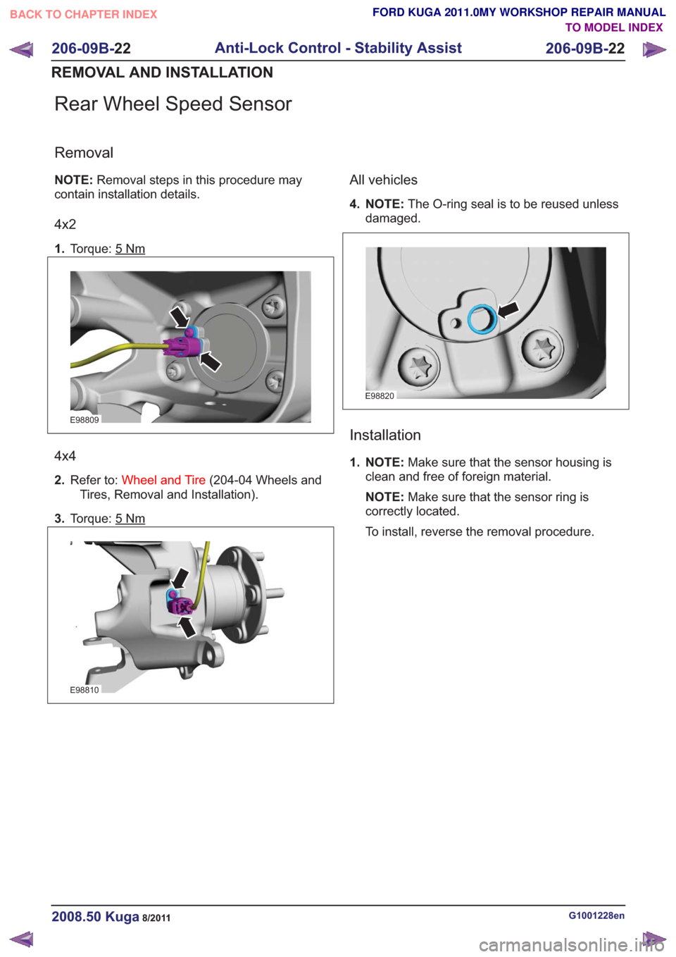
Rear Wheel Speed Sensor
Removal
NOTE:Removal steps in this procedure may
contain installation details.
4x2
1. Torque: 5Nm
E98809
4x4
2.Refer to: Wheel and Tire (204-04 Wheels and
Tires, Removal and Installation).
3. Torque: 5
Nm
E98810
All vehicles
4. NOTE: The O-ring seal is to be reused unless
damaged.
E98820
Installation
1. NOTE: Make sure that the sensor housing is
clean and free of foreign material.
NOTE: Make sure that the sensor ring is
correctly located.
To install, reverse the removal procedure.
G1001228en2008.50 Kuga8/2011
206-09B- 22
Anti-Lock Control - Stability Assist
206-09B- 22
REMOVAL AND INSTALLATION
TO MODEL INDEX
BACK TO CHAPTER INDEX
FORD KUGA 2011.0MY WORKSHOP REPAIR MANUAL
Page 1441 of 2057
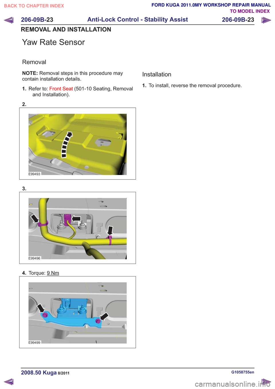
Yaw Rate Sensor
Removal
NOTE:Removal steps in this procedure may
contain installation details.
1. Refer to: Front Seat (501-10 Seating, Removal
and Installation).
2.
E99493
3.
E99496
4. Torque: 9Nm
E99499
Installation
1.To install, reverse the removal procedure.
G1058755en2008.50 Kuga8/2011
206-09B- 23
Anti-Lock Control - Stability Assist
206-09B- 23
REMOVAL AND INSTALLATION
TO MODEL INDEX
BACK TO CHAPTER INDEX
FORD KUGA 2011.0MY WORKSHOP REPAIR MANUAL
Page 1443 of 2057
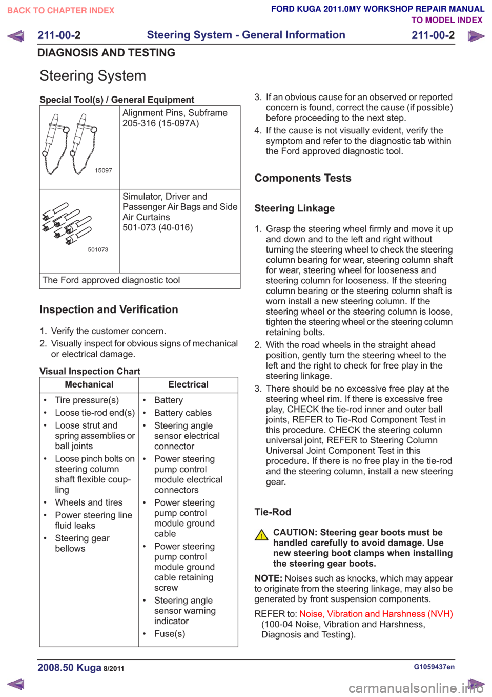
Steering System
Special Tool(s) / General EquipmentAlignment Pins, Subframe
205-316 (15-097A)
15097
Simulator, Driver and
Passenger Air Bags and Side
Air Curtains
501-073 (40-016)
501073
The Ford approved diagnostic tool
Inspection and Verification
1. Verify the customer concern.
2. Visually inspect for obvious signs of mechanicalor electrical damage.
Visual Inspection Chart
Electrical
Mechanical
• Battery
• Battery cables
• Steering anglesensor electrical
connector
• Power steering pump control
module electrical
connectors
• Power steering pump control
module ground
cable
• Power steering pump control
module ground
cable retaining
screw
• Steering angle sensor warning
indicator
• Fuse(s)
• Tire pressure(s)
• Loose tie-rod end(s)
• Loose strut and
spring assemblies or
ball joints
• Loose pinch bolts on steering column
shaft flexible coup-
ling
• Wheels and tires
• Power steering line fluid leaks
• Steering gear bellows 3. If an obvious cause for an observed or reported
concern is found, correct the cause (if possible)
before proceeding to the next step.
4. If the cause is not visually evident, verify the symptom and refer to the diagnostic tab within
the Ford approved diagnostic tool.
Components Tests
Steering Linkage
1. Grasp the steering wheel firmly and move it upand down and to the left and right without
turning the steering wheel to check the steering
column bearing for wear, steering column shaft
for wear, steering wheel for looseness and
steering column for looseness. If the steering
column bearing or the steering column shaft is
worn install a new steering column. If the
steering wheel or the steering column is loose,
tighten the steering wheel or the steering column
retaining bolts.
2. With the road wheels in the straight ahead position, gently turn the steering wheel to the
left and the right to check for free play in the
steering linkage.
3. There should be no excessive free play at the steering wheel rim. If there is excessive free
play, CHECK the tie-rod inner and outer ball
joints, REFER to Tie-Rod Component Test in
this procedure. CHECK the steering column
universal joint, REFER to Steering Column
Universal Joint Component Test in this
procedure. If there is no free play in the tie-rod
and the steering column, install a new steering
gear.
Tie-Rod
CAUTION: Steering gear boots must be
handled carefully to avoid damage. Use
new steering boot clamps when installing
the steering gear boots.
NOTE: Noises such as knocks, which may appear
to originate from the steering linkage, may also be
generated by front suspension components.
REFER to: Noise, Vibration and Harshness (NVH)
(100-04 Noise, Vibration and Harshness,
Diagnosis and Testing).
G1059437en2008.50 Kuga8/2011
211-00- 2
Steering System - General Information
211-00- 2
DIAGNOSIS AND TESTING
TO MODEL INDEX
BACK TO CHAPTER INDEX
FORD KUGA 2011.0MY WORKSHOP REPAIR MANUAL
Page 1458 of 2057
SECTION 211-02 Power Steering
VEHICLE APPLICATION:2008.50 Kuga
PA G E
CONTENTS
DESCRIPTION AND OPERATION
211-02-2
Power Steering (Component Location) ........................................................................\
......
211-02-3
Power Steering (Overview) ........................................................................\
.........................
211-02-3
Power Steering ........................................................................\
...........................................
211-02-4
Steering gear ........................................................................\
..............................................
211-02-5
Electro-hydraulic power steering pump ........................................................................\
......
211-02-6
Pressure and return lines ........................................................................\
...........................
211-02-7
Power Steering (System Operation and Component Description) .....................................
211-02-7
System Diagram ........................................................................\
.........................................
211-02-8
System Operation ........................................................................\
.......................................
211-02-8
Electronic principle of operation ........................................................................\
..............
211-02-9
Hydraulic principle of operation ........................................................................\
..............
211-02-9
Component Description ........................................................................\
..............................
211-02-9
Electro-hydraulic power steering pump ........................................................................\
..
211-02-10
Integrated steering angle sensor - vehicles built up to 09/2009 .....................................
211-02-11
Brushless DC motor with integral power steering module..............................................
REMOVAL AND INSTALLATION
211-02-13
(13 443 0)
Power Steering Pressure Line and Return Line Assembly — 2.5L Duratec
(147kW/200PS) - VI5 ........................................................................\
............
211-02-18
(13 434 0)
Power Steering Pump — 2.5L Duratec (147kW/200PS) - VI5 .......................
211-02-21
(13 440 0;
13 443 0)
Power Steering Pump to Steering Gear Pressure Line — 2.5L Duratec
(147kW/200PS) - VI5 ........................................................................\
............
211-02-25
(13 116 0)
Steering Gear ........................................................................\
.........................
211-02-36
(13 439 0)
Steering Gear to Power Steering Fluid Reservoir Return Line — 2.5L Duratec
(147kW/200PS) - VI5 ........................................................................\
............
211-02-1
Power Steering
211-02- 1
.
TO MODEL INDEX
BACK TO CHAPTER INDEX
FORD KUGA 2011.0MY WORKSHOP REPAIR MANUAL
Page 1459 of 2057
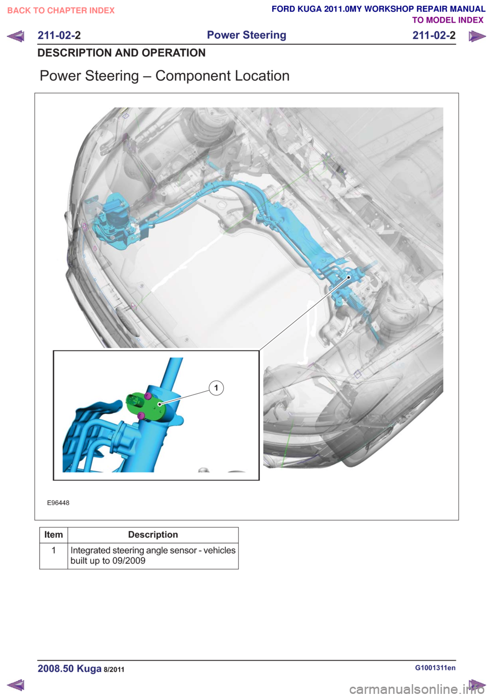
Power Steering – Component Location
E96448
1
Description
Item
Integrated steering angle sensor - vehicles
built up to 09/2009
1
G1001311en2008.50 Kuga8/2011
211-02-
2
Power Steering
211-02- 2
DESCRIPTION AND OPERATION
TO MODEL INDEX
BACK TO CHAPTER INDEX
FORD KUGA 2011.0MY WORKSHOP REPAIR MANUAL
Page 1461 of 2057
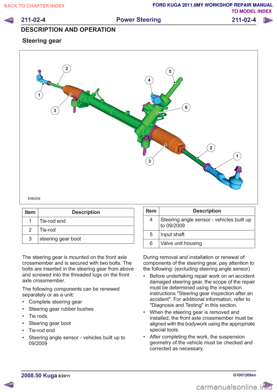
Steering gear
E96209
1
2
3
4
5
1
2
63
Description
Item
Tie-rod end
1
Tie-rod
2
steering gear boot
3Description
Item
Steering angle sensor - vehicles built up
to 09/2009
4
Input shaft
5
Valve unit housing
6
The steering gear is mounted on the front axle
crossmember and is secured with two bolts. The
bolts are inserted in the steering gear from above
and screwed into the threaded lugs on the front
axle crossmember.
The following components can be renewed
separately or as a unit:
• Complete steering gear
• Steering gear rubber bushes
• Tie rods.
• Steering gear boot
• Tie-rod end
• Steering angle sensor - vehicles built up to 09/2009 During removal and installation or renewal of
components of the steering gear, pay attention to
the following: (excluding steering angle sensor)
• Before undertaking repair work on an accident
damaged steering gear, the scope of the repair
must be determined using the inspection
instructions "Steering gear inspection after an
accident". For additional information, refer to
"Diagnosis and Testing" in this section.
• When the steering gear is removed and installed, the front axle crossmember must be
aligned with the bodywork using the appropriate
special tools.
• After completing the work, the suspension geometry of the vehicle must be checked and
corrected as necessary.
G1001269en2008.50 Kuga8/2011
211-02- 4
Power Steering
211-02- 4
DESCRIPTION AND OPERATION
TO MODEL INDEX
BACK TO CHAPTER INDEX
FORD KUGA 2011.0MY WORKSHOP REPAIR MANUAL
Page 1465 of 2057
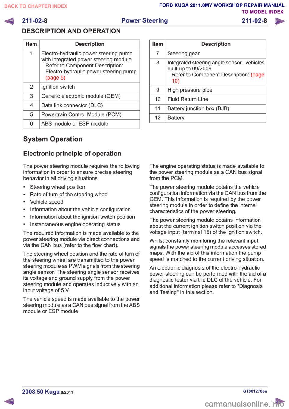
Description
Item
Electro-hydraulic power steering pump
with integrated power steering moduleRefer to Component Description:
Electro-hydraulic power steering pump
(page5)
1
Ignition switch
2
Generic electronic module (GEM)
3
Data link connector (DLC)
4
Powertrain Control Module (PCM)
5
ABS module or ESP module
6Description
Item
Steering gear
7
Integrated steering angle sensor - vehicles
built up to 09/2009RefertoComponentDescription:(page
10)
8
High pressure pipe
9
Fluid Return Line
10
Battery junction box (BJB)
11
Battery
12
System Operation
Electronic principle of operation
The power steering module requires the following
information in order to ensure precise steering
behavior in all driving situations:
• Steering wheel position
• Rate of turn of the steering wheel
• Vehicle speed
• Information about the vehicle configuration
• Information about the ignition switch position
• Instantaneous engine operating status
The required information is made available to the
power steering module via direct connections and
via the CAN bus (refer to the flow chart).
The steering wheel position and the rate of turn of
the steering wheel are transmitted to the power
steering module as PWM signals from the steering
angle sensor. The steering angle sensor receives
its voltage and ground supply from the power
steering module and operates inductively with an
input voltage of 5 V.
The vehicle speed is made available to the power
steering module as a CAN bus signal from the ABS
module or ESP module. The engine operating status is made available to
the power steering module as a CAN bus signal
from the PCM.
The power steering module obtains the vehicle
configuration information via the CAN bus from the
GEM. This information is required by the power
steering module in order to define the internal
characteristics of the power steering.
The power steering module obtains information
about the current ignition switch position via the
voltage input (terminal 15) of the ignition switch.
Whilst constantly monitoring the relevant input
signals the power steering module accesses stored
maps. With the aid of this information the pump
speed is matched to the current driving situation.
An electronic diagnosis of the electro-hydraulic
power steering can be performed with the aid of a
diagnostic tester via the DLC of the vehicle. For
additional information please refer to "Diagnosis
and Testing" in this section.
G1001270en2008.50 Kuga8/2011
211-02-
8
Power Steering
211-02- 8
DESCRIPTION AND OPERATION
TO MODEL INDEX
BACK TO CHAPTER INDEX
FORD KUGA 2011.0MY WORKSHOP REPAIR MANUAL