sensor FORD KUGA 2011 1.G Repair Manual
[x] Cancel search | Manufacturer: FORD, Model Year: 2011, Model line: KUGA, Model: FORD KUGA 2011 1.GPages: 2057
Page 1193 of 2057
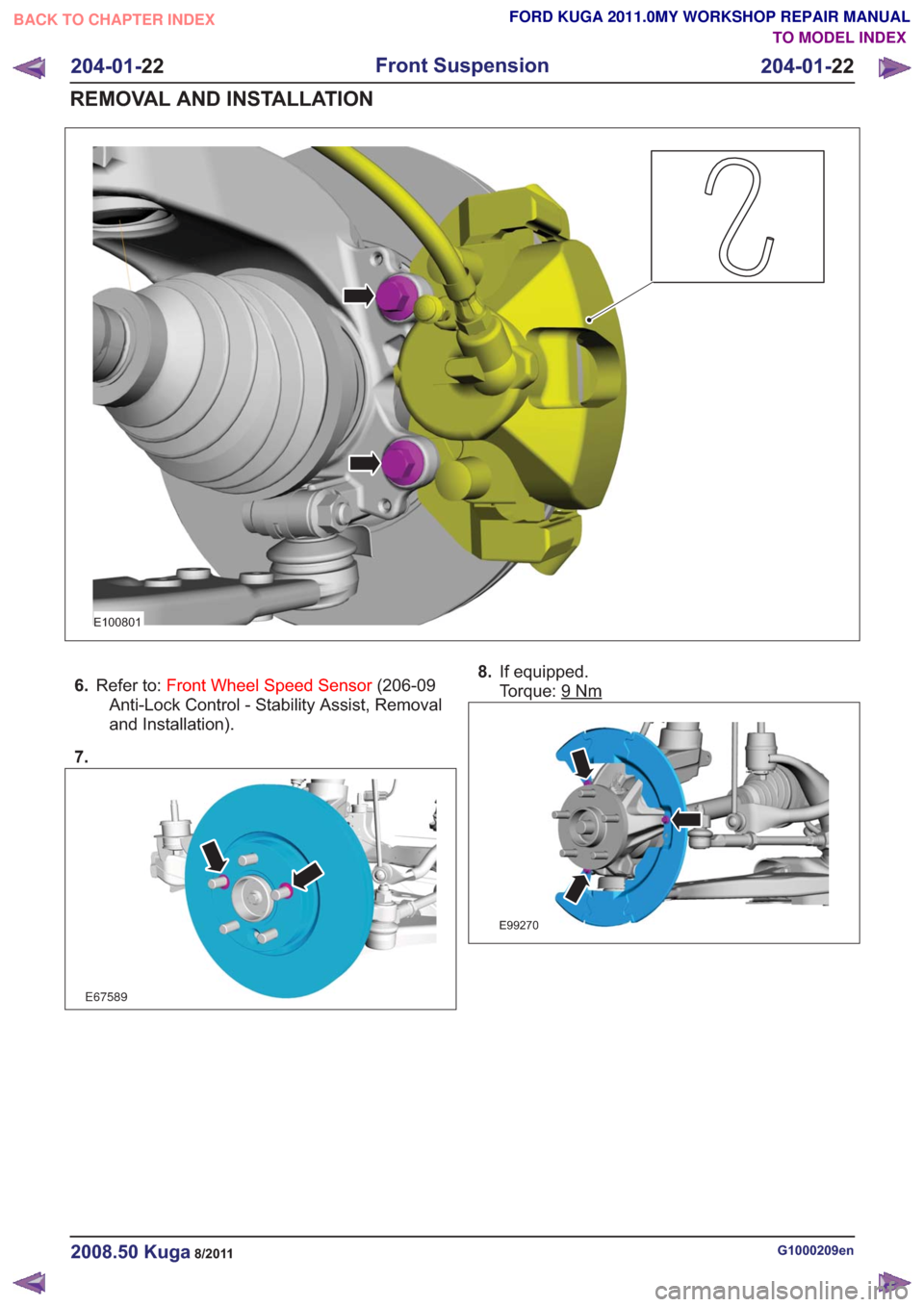
E100801
6.Refer to: Front Wheel Speed Sensor (206-09
Anti-Lock Control - Stability Assist, Removal
and Installation).
7.
E67589
8. If equipped.
Torque: 9
Nm
E99270
G1000209en2008.50 Kuga8/2011
204-01- 22
Front Suspension
204-01- 22
REMOVAL AND INSTALLATION
TO MODEL INDEX
BACK TO CHAPTER INDEX
FORD KUGA 2011.0MY WORKSHOP REPAIR MANUAL
Page 1208 of 2057
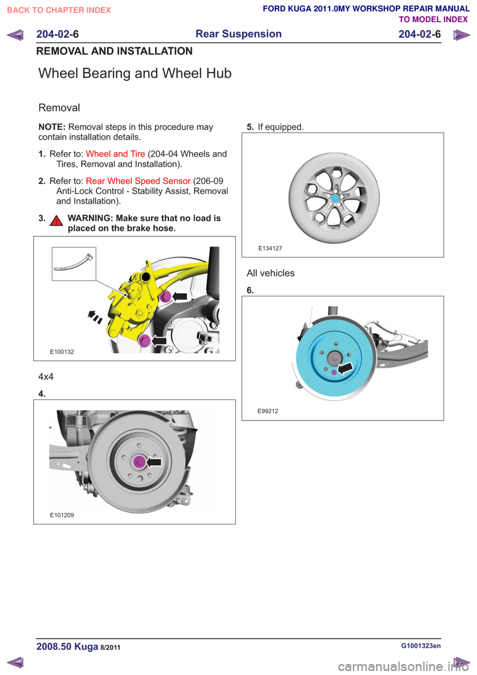
Wheel Bearing and Wheel Hub
Removal
NOTE:Removal steps in this procedure may
contain installation details.
1. Refer to: Wheel and Tire (204-04 Wheels and
Tires, Removal and Installation).
2. Refer to: Rear Wheel Speed Sensor (206-09
Anti-Lock Control - Stability Assist, Removal
and Installation).
3. WARNING: Make sure that no load is placed on the brake hose.
E100132
4x4
4.
E101209
5.If equipped.
E134127
All vehicles
6.
E99212
G1001323en2008.50 Kuga8/2011
204-02- 6
Rear Suspension
204-02- 6
REMOVAL AND INSTALLATION
TO MODEL INDEX
BACK TO CHAPTER INDEX
FORD KUGA 2011.0MY WORKSHOP REPAIR MANUAL
Page 1210 of 2057
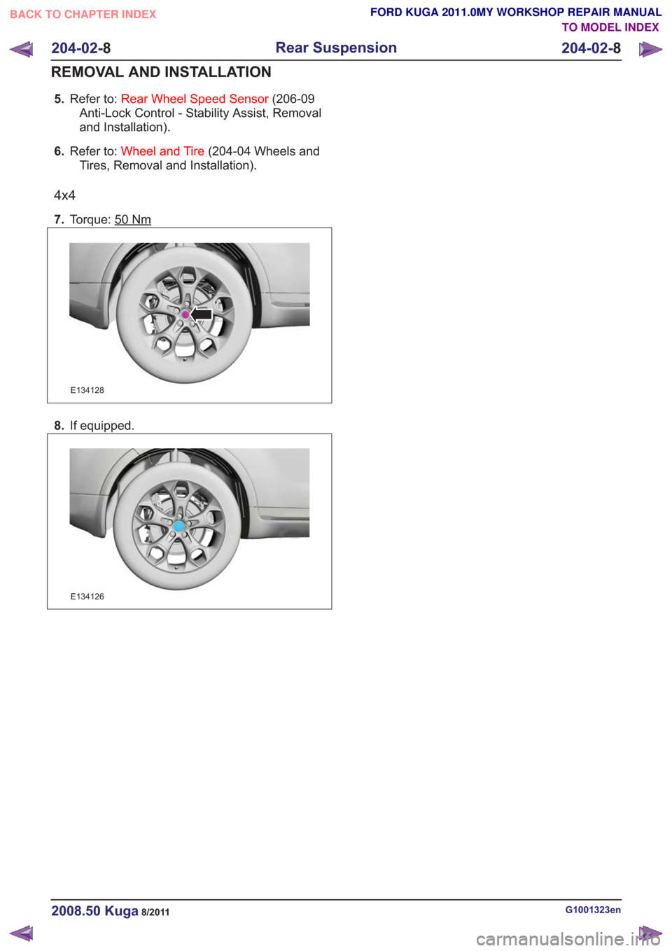
5.Refer to: Rear Wheel Speed Sensor (206-09
Anti-Lock Control - Stability Assist, Removal
and Installation).
6. Refer to: Wheel and Tire (204-04 Wheels and
Tires, Removal and Installation).
4x4
7. Torque: 50Nm
E134128
8.If equipped.
E134126
G1001323en2008.50 Kuga8/2011
204-02- 8
Rear Suspension
204-02- 8
REMOVAL AND INSTALLATION
TO MODEL INDEX
BACK TO CHAPTER INDEX
FORD KUGA 2011.0MY WORKSHOP REPAIR MANUAL
Page 1230 of 2057
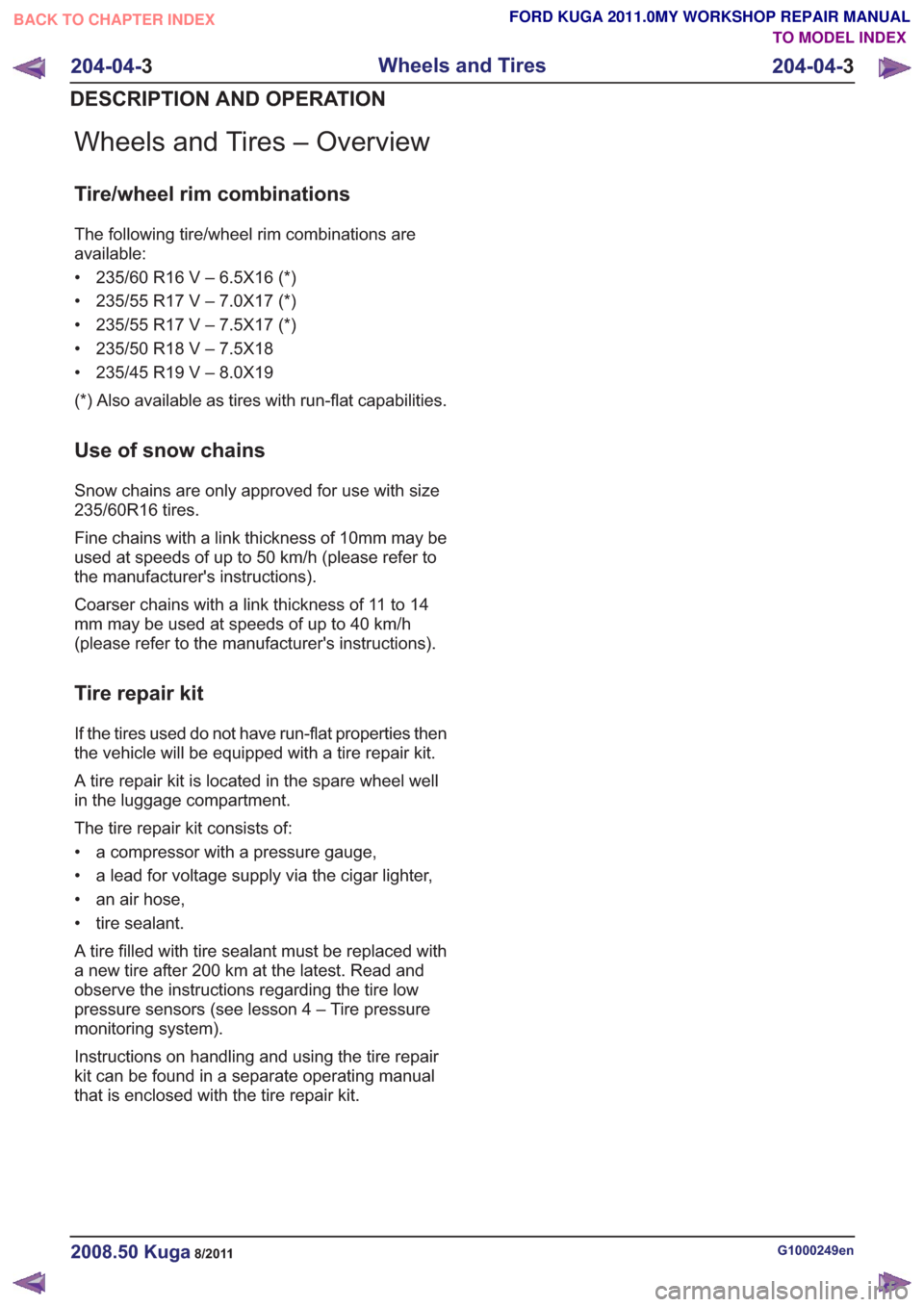
Wheels and Tires – Overview
Tire/wheel rim combinations
The following tire/wheel rim combinations are
available:
• 235/60 R16 V – 6.5X16 (*)
• 235/55 R17 V – 7.0X17 (*)
• 235/55 R17 V – 7.5X17 (*)
• 235/50 R18 V – 7.5X18
• 235/45 R19 V – 8.0X19
(*) Also available as tires with run-flat capabilities.
Use of snow chains
Snow chains are only approved for use with size
235/60R16 tires.
Fine chains with a link thickness of 10mm may be
used at speeds of up to 50 km/h (please refer to
the manufacturer's instructions).
Coarser chains with a link thickness of 11 to 14
mm may be used at speeds of up to 40 km/h
(please refer to the manufacturer's instructions).
Tire repair kit
If the tires used do not have run-flat properties then
the vehicle will be equipped with a tire repair kit.
A tire repair kit is located in the spare wheel well
in the luggage compartment.
The tire repair kit consists of:
• a compressor with a pressure gauge,
• a lead for voltage supply via the cigar lighter,
• an air hose,
• tire sealant.
A tire filled with tire sealant must be replaced with
a new tire after 200 km at the latest. Read and
observe the instructions regarding the tire low
pressure sensors (see lesson 4 – Tire pressure
monitoring system).
Instructions on handling and using the tire repair
kit can be found in a separate operating manual
that is enclosed with the tire repair kit.
G1000249en2008.50 Kuga8/2011
204-04-3
Wheels and Tires
204-04- 3
DESCRIPTION AND OPERATION
TO MODEL INDEX
BACK TO CHAPTER INDEX
FORD KUGA 2011.0MY WORKSHOP REPAIR MANUAL
Page 1232 of 2057
Tire Pressure Monitoring System (TPMS) – Overview
Description of operation
The tire pressure monitoring system is able to
detect loss of air in a tire at an early stage and warn
the driver. Because it can only compare the
behavior of the tires with each other, it is not
possible to draw conclusions about the absolute
tire pressure. It is also not possible to monitor the
spare tire pressure. In order for the system to
operate correctly, the tire pressures must be
regularly checked and corrected and the system
subsequently initialized (see below).
The tire pressure monitoring system used here,
depending on the equipment level, is built into the
anti-lock braking system (ABS) as an extra function
and therefore does not have its own sensors.
The ABS module determines the loss of pressure
in the tires by calculation using the wheel speed
sensors of the ABS system. If a tire loses pressure,
its diameter decreases and the speed of the wheel
therefore increases. If the ABS module detects
such a loss in pressure, it sends a signal to the
instrument cluster via the CAN bus and a warning
message is displayed in the driver information
system. The warning threshold depends among
other things on the dimension of the tires being
used, the vehicle operating conditions and the
status at the last initialization. Since neither the
absolute tire pressure nor the position of the tire is
known, after a tire pressure warning the pressure
of all the tires must be checked and the system
re-initialized. If necessary, the cause of the loss of
pressure must be investigated.
Furthermore, regular pressure checks are
necessary. The system must be initialized after a
tire is changed, winter or summer tires fitted, the
pressures corrected or adjusted to suit the vehicle
load. This can be done by the driver using the
driver information system. For further information,
see: Owner’s Manual.
G1001290en2008.50 Kuga8/2011
204-04-5
Wheels and Tires
204-04- 5
DESCRIPTION AND OPERATION
TO MODEL INDEX
BACK TO CHAPTER INDEX
FORD KUGA 2011.0MY WORKSHOP REPAIR MANUAL
Page 1254 of 2057
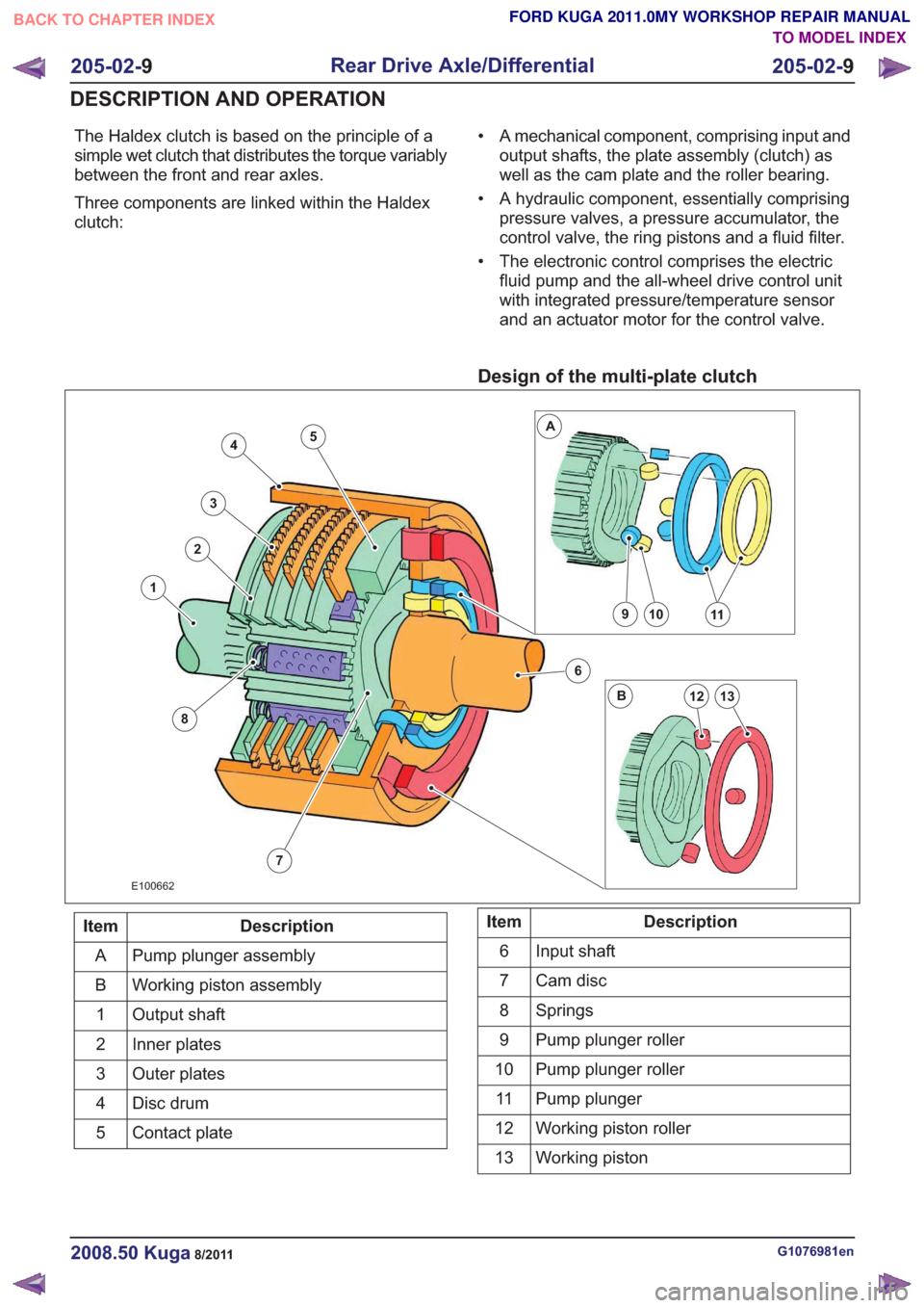
The Haldex clutch is based on the principle of a
simple wet clutch that distributes the torque variably
between the front and rear axles.
Three components are linked within the Haldex
clutch:• A mechanical component, comprising input and
output shafts, the plate assembly (clutch) as
well as the cam plate and the roller bearing.
• A hydraulic component, essentially comprising pressure valves, a pressure accumulator, the
control valve, the ring pistons and a fluid filter.
• The electronic control comprises the electric fluid pump and the all-wheel drive control unit
with integrated pressure/temperature sensor
and an actuator motor for the control valve.
Design of the multi-plate clutch
7
4
3
2
8
1
6
10911
13
A
B12
5
E100662
Description
Item
Pump plunger assembly
A
Working piston assembly
B
Output shaft
1
Inner plates
2
Outer plates
3
Disc drum
4
Contact plate
5Description
Item
Input shaft
6
Cam disc
7
Springs
8
Pump plunger roller
9
Pump plunger roller
10
Pump plunger
11
Working piston roller
12
Working piston
13
G1076981en2008.50 Kuga8/2011
205-02- 9
Rear Drive Axle/Differential
205-02- 9
DESCRIPTION AND OPERATION
TO MODEL INDEX
BACK TO CHAPTER INDEX
FORD KUGA 2011.0MY WORKSHOP REPAIR MANUAL
Page 1255 of 2057
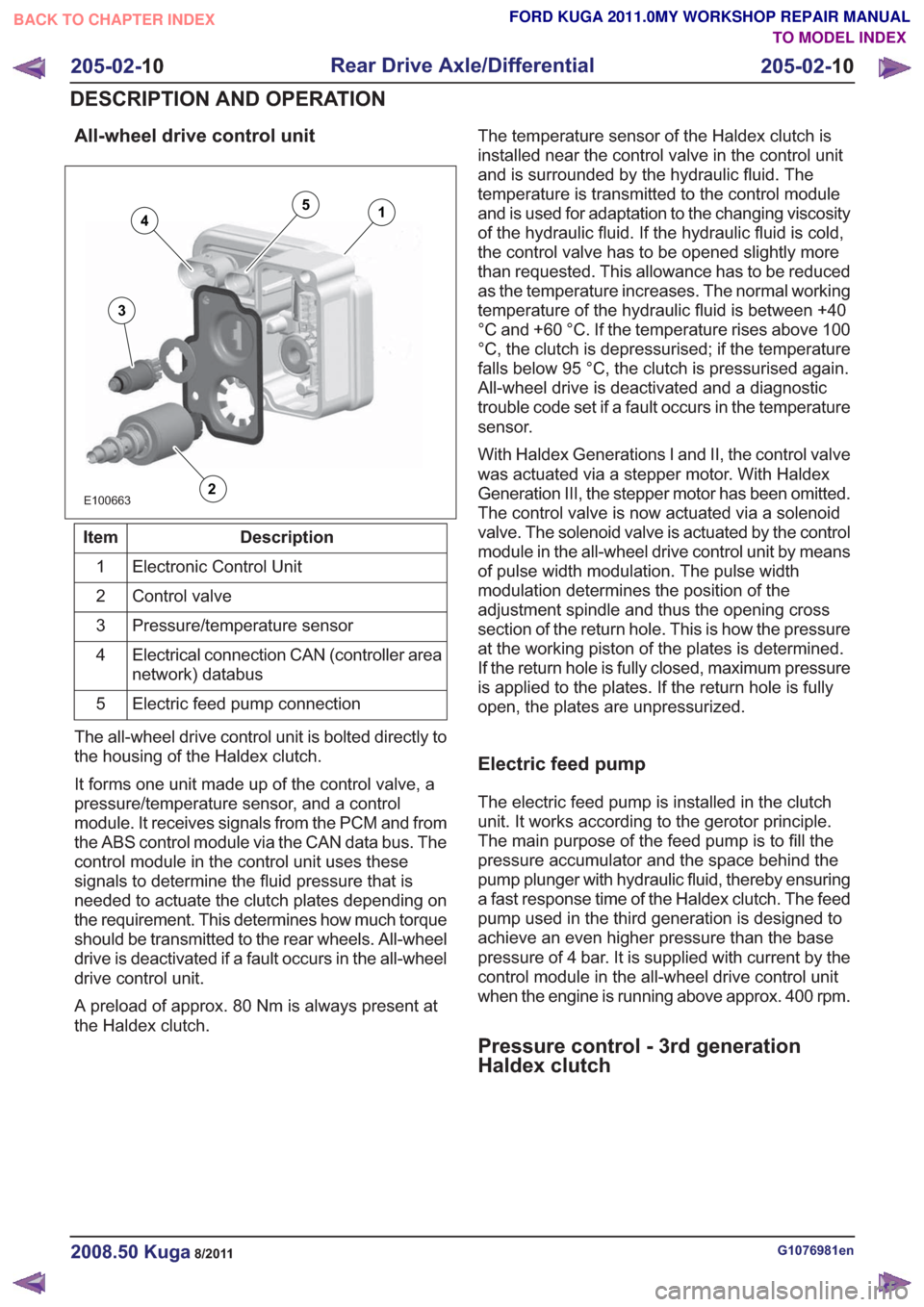
All-wheel drive control unit
E100663
14
3
2
5
Description
Item
Electronic Control Unit
1
Control valve
2
Pressure/temperature sensor
3
Electrical connection CAN (controller area
network) databus
4
Electric feed pump connection
5
The all-wheel drive control unit is bolted directly to
the housing of the Haldex clutch.
It forms one unit made up of the control valve, a
pressure/temperature sensor, and a control
module. It receives signals from the PCM and from
the ABS control module via the CAN data bus. The
control module in the control unit uses these
signals to determine the fluid pressure that is
needed to actuate the clutch plates depending on
the requirement. This determines how much torque
should be transmitted to the rear wheels. All-wheel
drive is deactivated if a fault occurs in the all-wheel
drive control unit.
A preload of approx. 80 Nm is always present at
the Haldex clutch. The temperature sensor of the Haldex clutch is
installed near the control valve in the control unit
and is surrounded by the hydraulic fluid. The
temperature is transmitted to the control module
and is used for adaptation to the changing viscosity
of the hydraulic fluid. If the hydraulic fluid is cold,
the control valve has to be opened slightly more
than requested. This allowance has to be reduced
as the temperature increases. The normal working
temperature of the hydraulic fluid is between +40
°C and +60 °C. If the temperature rises above 100
°C, the clutch is depressurised; if the temperature
falls below 95 °C, the clutch is pressurised again.
All-wheel drive is deactivated and a diagnostic
trouble code set if a fault occurs in the temperature
sensor.
With Haldex Generations I and II, the control valve
was actuated via a stepper motor. With Haldex
Generation III, the stepper motor has been omitted.
The control valve is now actuated via a solenoid
valve. The solenoid valve is actuated by the control
module in the all-wheel drive control unit by means
of pulse width modulation. The pulse width
modulation determines the position of the
adjustment spindle and thus the opening cross
section of the return hole. This is how the pressure
at the working piston of the plates is determined.
If the return hole is fully closed, maximum pressure
is applied to the plates. If the return hole is fully
open, the plates are unpressurized.
Electric feed pump
The electric feed pump is installed in the clutch
unit. It works according to the gerotor principle.
The main purpose of the feed pump is to fill the
pressure accumulator and the space behind the
pump plunger with hydraulic fluid, thereby ensuring
a fast response time of the Haldex clutch. The feed
pump used in the third generation is designed to
achieve an even higher pressure than the base
pressure of 4 bar. It is supplied with current by the
control module in the all-wheel drive control unit
when the engine is running above approx. 400 rpm.
Pressure control - 3rd generation
Haldex clutch
G1076981en2008.50 Kuga8/2011
205-02-
10
Rear Drive Axle/Differential
205-02- 10
DESCRIPTION AND OPERATION
TO MODEL INDEX
BACK TO CHAPTER INDEX
FORD KUGA 2011.0MY WORKSHOP REPAIR MANUAL
Page 1256 of 2057
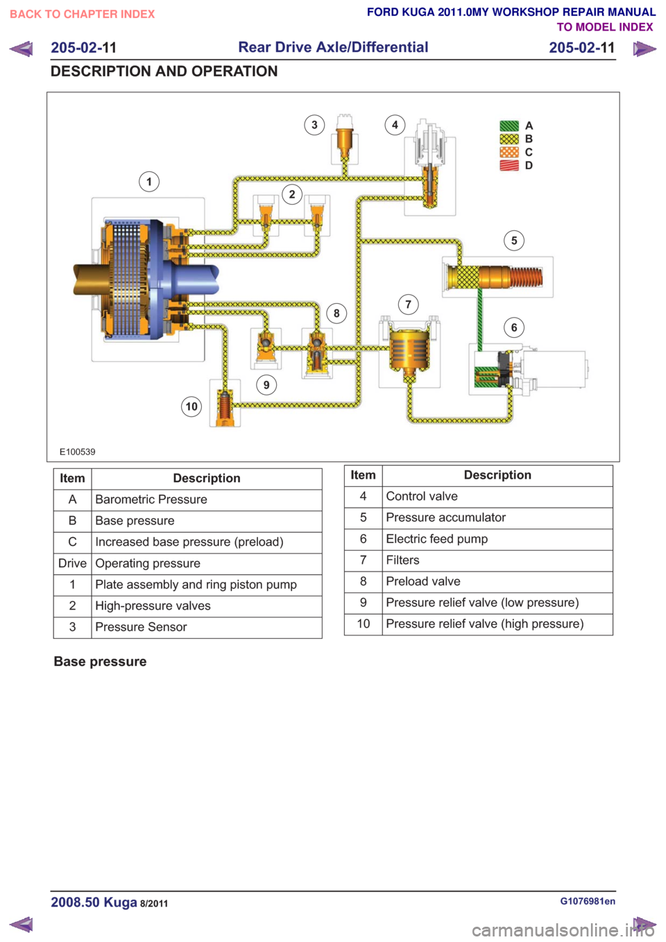
E100539
34
2
1
9
8
10
7
6
5A
B
C
D
Description
Item
Barometric Pressure
A
Base pressure
B
Increased base pressure (preload)
C
Operating pressure
Drive
Plate assembly and ring piston pump
1
High-pressure valves
2
Pressure Sensor
3Description
Item
Control valve
4
Pressure accumulator
5
Electric feed pump
6
Filters7
Preload valve
8
Pressure relief valve (low pressure)
9
Pressure relief valve (high pressure)
10
Base pressure
G1076981en2008.50 Kuga8/2011
205-02- 11
Rear Drive Axle/Differential
205-02- 11
DESCRIPTION AND OPERATION
TO MODEL INDEX
BACK TO CHAPTER INDEX
FORD KUGA 2011.0MY WORKSHOP REPAIR MANUAL
Page 1260 of 2057
1
2
3
4
E115887
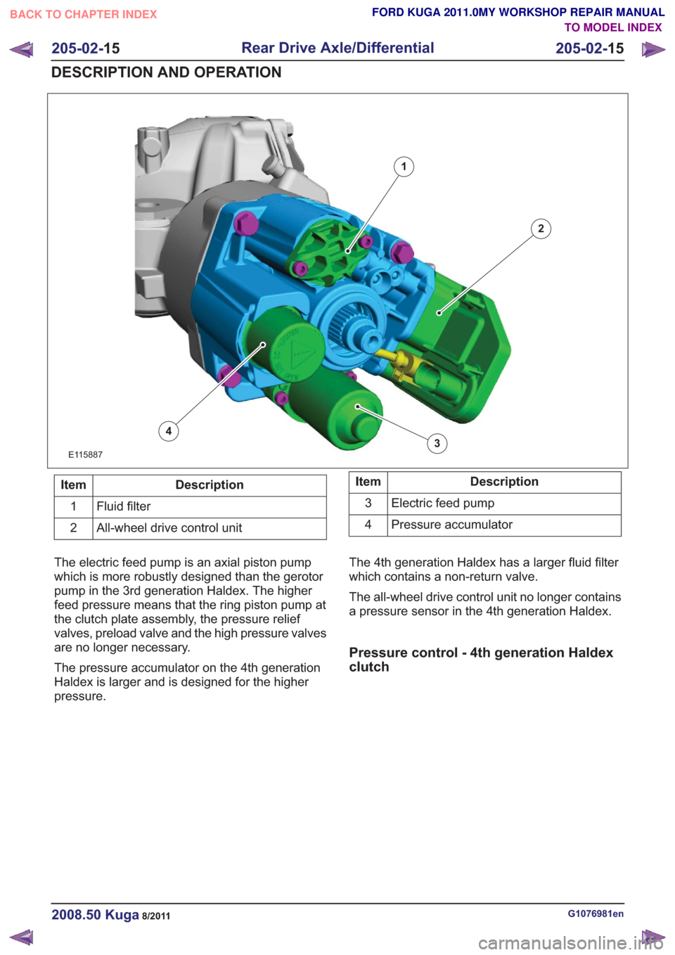
Description
Item
Fluid filter
1
All-wheel drive control unit
2Description
Item
Electric feed pump
3
Pressure accumulator
4
The electric feed pump is an axial piston pump
which is more robustly designed than the gerotor
pump in the 3rd generation Haldex. The higher
feed pressure means that the ring piston pump at
the clutch plate assembly, the pressure relief
valves, preload valve and the high pressure valves
are no longer necessary.
The pressure accumulator on the 4th generation
Haldex is larger and is designed for the higher
pressure. The 4th generation Haldex has a larger fluid filter
which contains a non-return valve.
The all-wheel drive control unit no longer contains
a pressure sensor in the 4th generation Haldex.
Pressure control - 4th generation Haldex
clutch
G1076981en2008.50 Kuga8/2011
205-02-
15
Rear Drive Axle/Differential
205-02- 15
DESCRIPTION AND OPERATION
TO MODEL INDEX
BACK TO CHAPTER INDEX
FORD KUGA 2011.0MY WORKSHOP REPAIR MANUAL
Page 1418 of 2057
Anti-Lock Control
schematic
and connector information.
General Equipment
The Ford approved diagnostic tool
Inspection and Verification
1. Verify the customer concern.
2. Visually inspect for obvious signs of mechanical or electrical damage.
Visual Inspection Chart
Electrical
Mechanical
• Fuse(s)
• Electricalconnector(s)
• Wiring harness(s).
• Anti-lock brake system (ABS)
module
• Wheel speed
sensor(s)
• Wheel speed sensor ring(s)
3. If an obvious cause for an observed or reported concern is found, correct the cause (if possible)
before proceeding to the next step.
4. If the cause is not visually evident, verify the symptom and refer to the diagnostic tab within
the Ford approved diagnostic tool.
G1058976en2008.50 Kuga8/2011
206-09A- 5
Anti-Lock Control
206-09A- 5
DIAGNOSIS AND TESTING
TO MODEL INDEX
BACK TO CHAPTER INDEX
FORD KUGA 2011.0MY WORKSHOP REPAIR MANUAL
Refer to
Wiring Diagrams Section 206-09A, for