diagram FORD KUGA 2011 1.G Workshop Manual
[x] Cancel search | Manufacturer: FORD, Model Year: 2011, Model line: KUGA, Model: FORD KUGA 2011 1.GPages: 2057
Page 45 of 2057
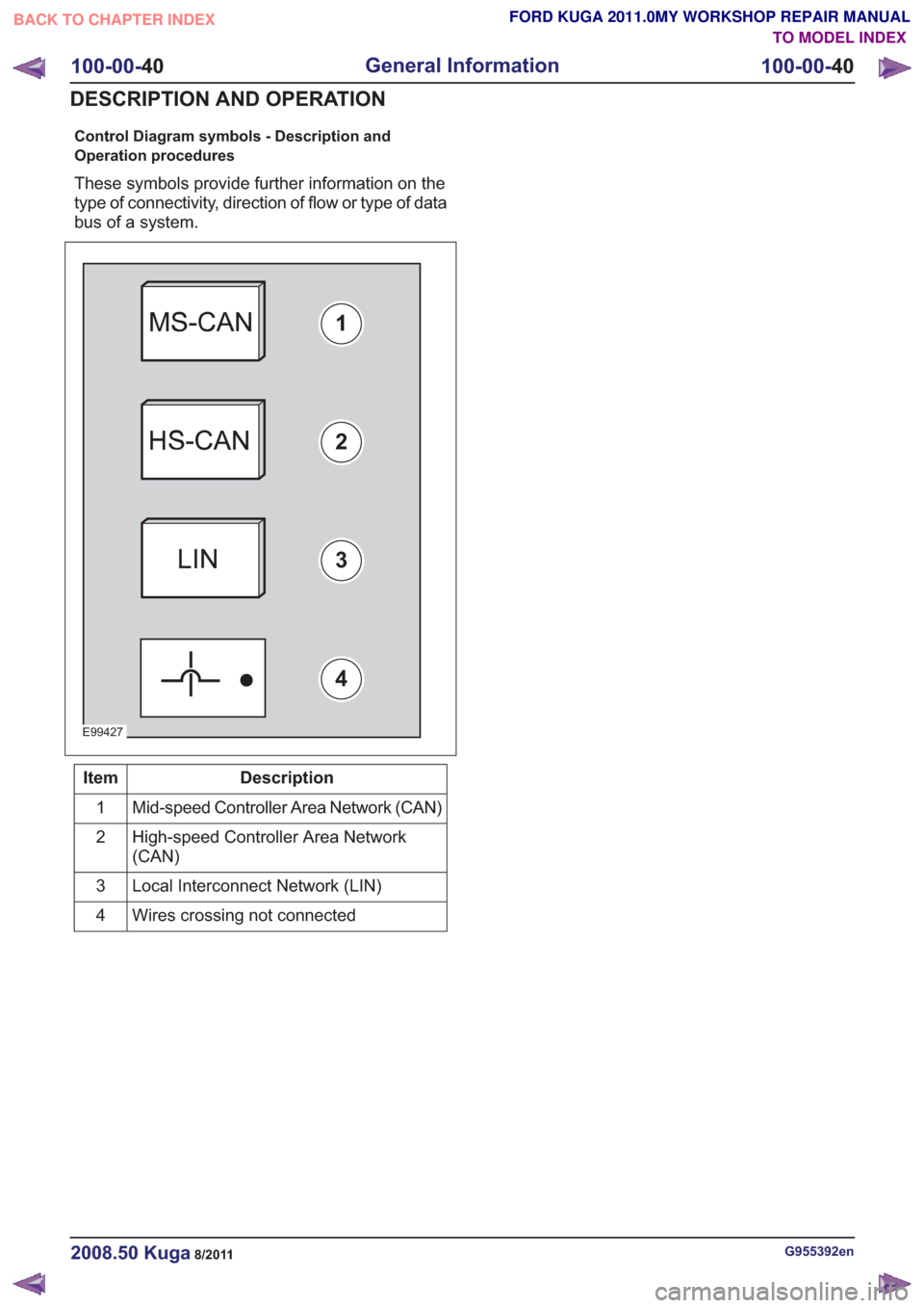
Control Diagram symbols - Description and
Operation procedures
These symbols provide further information on the
type of connectivity, direction of flow or type of data
bus of a system.
E99427
1
2
3
4
Description
Item
Mid-speed Controller Area Network (CAN)
1
High-speed Controller Area Network
(CAN)
2
Local Interconnect Network (LIN)
3
Wires crossing not connected
4
G955392en2008.50 Kuga8/2011
100-00- 40
General Information
100-00- 40
DESCRIPTION AND OPERATION
TO MODEL INDEX
BACK TO CHAPTER INDEX
FORD KUGA 2011.0MY WORKSHOP REPAIR MANUAL
Page 154 of 2057
SECTION 412-02 Auxiliary Climate Control
VEHICLE APPLICATION:
2008.50 Kuga
PAGE
CONTENTS
DESCRIPTION AND OPERATION
412-02-2
Auxiliary Climate Control (Component Location) ................................................................
412-02-4
Auxiliary Climate Control (Overview) ..................................................................................
412-02-4
Initial start-up of the fuel-fired booster heater .....................................................................
412-02-4
Lockout ...............................................................................................................................
412-02-4
Unlocking the control unit ...................................................................................................
412-02-5
Auxiliary Climate Control (System Operation and Component Description) ......................
412-02-5
System Diagram.................................................................................................................
412-02-12
System Operation ...............................................................................................................
412-02-12
Electric Booster Heater ...................................................................................................
412-02-12
Fuel-fired heater - function diagram................................................................................
412-02-13
Boost heat mode.............................................................................................................
412-02-13
Programmable fuel fired booster heater .........................................................................
412-02-13
Immediate start-up of the booster heater ........................................................................
412-02-13
Programmed start-up of the booster heater ....................................................................
412-02-14
Emergency shutoff ..........................................................................................................
412-02-14
Component Description ......................................................................................................412-02-14Electric Booster Heater...................................................................................................
412-02-14Detailed illustration of fuel-fired heater ...........................................................................
412-02-16Flame sensor..................................................................................................................
412-02-16Overheat Sensor.............................................................................................................
412-02-16ECT.................................................................................................................................
412-02-16Water pump....................................................................................................................
412-02-16Fuel pump.......................................................................................................................
REMOVAL AND INSTALLATION 412-02-17
Auxiliary Coolant Flow Pump ..............................................................................................
412-02-18
Electric Booster Heater .......................................................................................................
412-02-21
Fuel Fired Booster Heater — 2.5L Duratec (147kW/200PS) - VI5 .....................................
412-02-25
Fuel Fired Booster Heater Fuel Pump ................................................................................
DISASSEMBLY AND ASSEMBLY 412-02-26
Fuel Fired Booster Heater .................................................................................................. 412-02-1
Auxiliary Climate Control
412-02-1
.
TO MODEL INDEX
BACK TO CHAPTER INDEX
FORD KUGA 2011.0MY WORKSHOP REPAIR MANUAL
Page 158 of 2057

Auxiliary Climate Control – System Operation and Component
Description
System Diagram G1066982en
2008.50 Kuga 8/2011 412-02-5
Auxiliary Climate Control
412-02-5
DESCRIPTION AND OPERATIONTO MODEL INDEX
BACK TO CHAPTER INDEX
FORD KUGA 2011.0MY WORKSHOP REPAIR MANUAL
VIEW DIAGRAM ON THE NEXT PAGE
Page 165 of 2057
System Operation
Electric Booster Heater
In diesel vehicles which give off little residual heat,
a booster heater is used to heat the passenger
compartment rapidly in the case of low ambient
temperatures.
If the interior temperature has been set to HI, or if
the heater controls have been switched to the
highest setting, the two-zone air conditioning
system sends an "electric booster heater ON"
request signal to the CAN (controller area network)
via the medium speed GEM bus. If a manual air
conditioning system is installed, the signal is
transmitted via a conventional cable connection.
The GEM switches on the electric booster heater
depending on the following parameters:
• Engine coolant temperature is below 60 °C.
• Ambient air temperature is below 10 °C.
• Sufficient generator capacity is available.
The electric booster heater electronics activate
three output stages as a function of a pulse width
modulated signal PWM (pulse width modulation)
generated by the GEM. The output stages switch
the three heating elements of the electric booster
heater ON or OFF individually, whereby the heating
periods of the individual elements can overlap. Due
to the variable switch-on duration, continuously
variable temperature control is possible. The overall
heating power of the three heating elements is
linearly proportional to the PWM signal. If the PWM
signal is below 10% or above 95%, the electric
booster heater is not activated.
The electric booster heater is switched off when
an engine coolant temperature of 70°C or an
ambient air temperature of 20°C is exceeded.
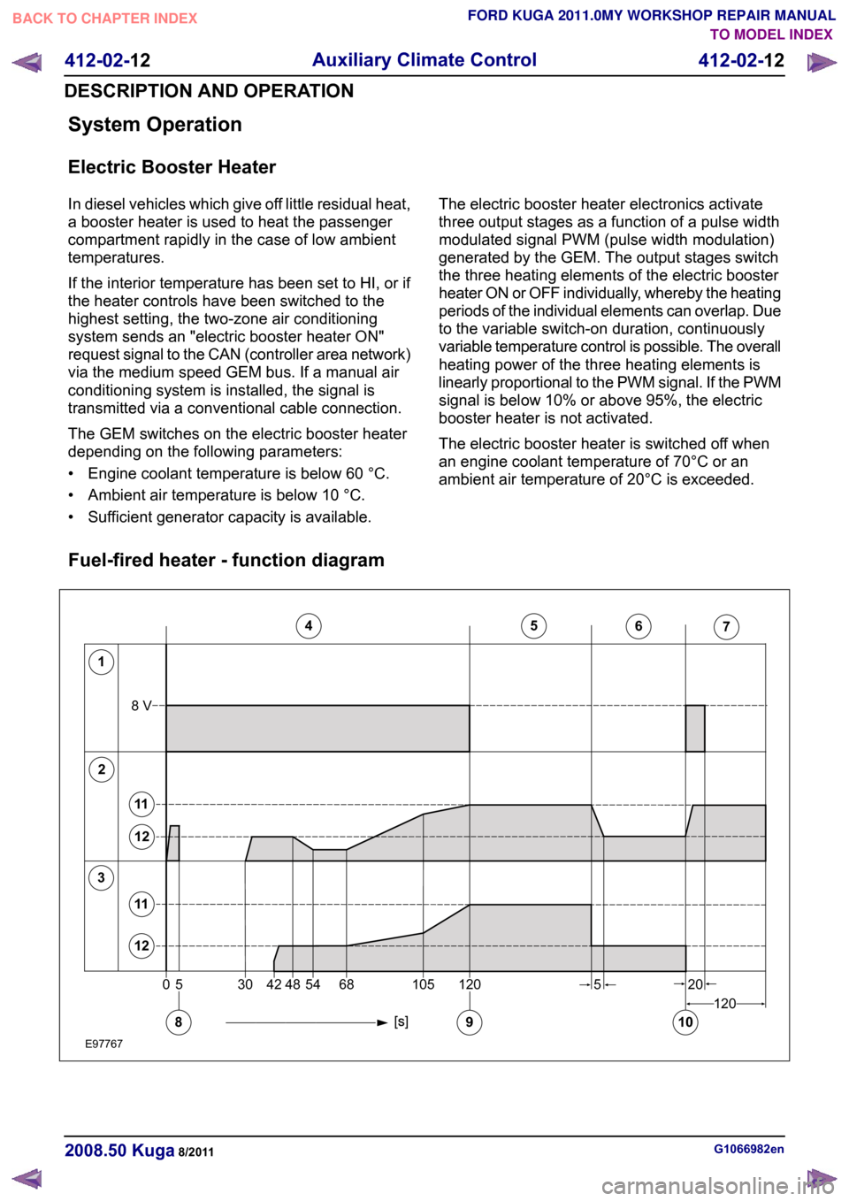
Fuel-fired heater - function diagram G1066982en
2008.50 Kuga 8/2011 412-02-12
Auxiliary Climate Control
412-02-12
DESCRIPTION AND OPERATIONTO MODEL INDEX
BACK TO CHAPTER INDEX
FORD KUGA 2011.0MY WORKSHOP REPAIR MANUAL12345671205304254481201056820108V58911121112E977670
Page 183 of 2057
Instrument Cluster and Panel Illumination
Refer to
Wiring Diagrams Section 413-00, for
schematic and connector information.
Principles of Operation
NOTE: A new instrument cluster must be
configured.
The instrument cluster and panel illumination
consists of dimmable and non-dimmable
illumination. The dimmable panel illumination is
controlled by the panel illumination switch (part of
the headlamp switch), which allows the brightness
level of the backlights to be adjusted dependent
on the customer preference. When the headlamp
switch is in the parking lamps ON or headlamps
ON position, the intensity of the backlighting can
be adjusted using the panel dimmer switch. The
non dimmable illumination allows for full intensity
dependant on the ignition switch position.
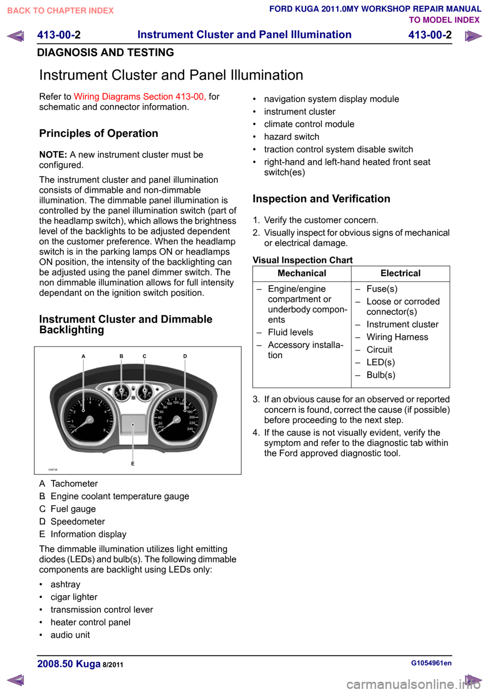
Instrument Cluster and Dimmable
Backlighting A.
Tachometer
B. Engine coolant temperature gauge
C. Fuel gauge
D. Speedometer
E. Information display
The dimmable illumination utilizes light emitting
diodes (LEDs) and bulb(s). The following dimmable
components are backlight using LEDs only:
• ashtray
• cigar lighter
• transmission control lever
• heater control panel
• audio unit • navigation system display module
• instrument cluster
• climate control module
• hazard switch
• traction control system disable switch
• right-hand and left-hand heated front seat
switch(es)
Inspection and Verification
1. Verify the customer concern.
2. Visually inspect for obvious signs of mechanical
or electrical damage.
Visual Inspection Chart Electrical
Mechanical
– Fuse(s)
– Loose or corrodedconnector(s)
– Instrument cluster
– Wiring Harness
– Circuit
– LED(s)
– Bulb(s)
– Engine/engine
compartment or
underbody compon-
ents
– Fluid levels
– Accessory installa- tion
3. If an obvious cause for an observed or reported concern is found, correct the cause (if possible)
before proceeding to the next step.
4. If the cause is not visually evident, verify the symptom and refer to the diagnostic tab within
the Ford approved diagnostic tool. G1054961en
2008.50 Kuga 8/2011 413-00-2
Instrument Cluster and Panel Illumination
413-00-2
DIAGNOSIS AND TESTINGTO MODEL INDEX
BACK TO CHAPTER INDEX
FORD KUGA 2011.0MY WORKSHOP REPAIR MANUALE98738ABCED
Page 184 of 2057
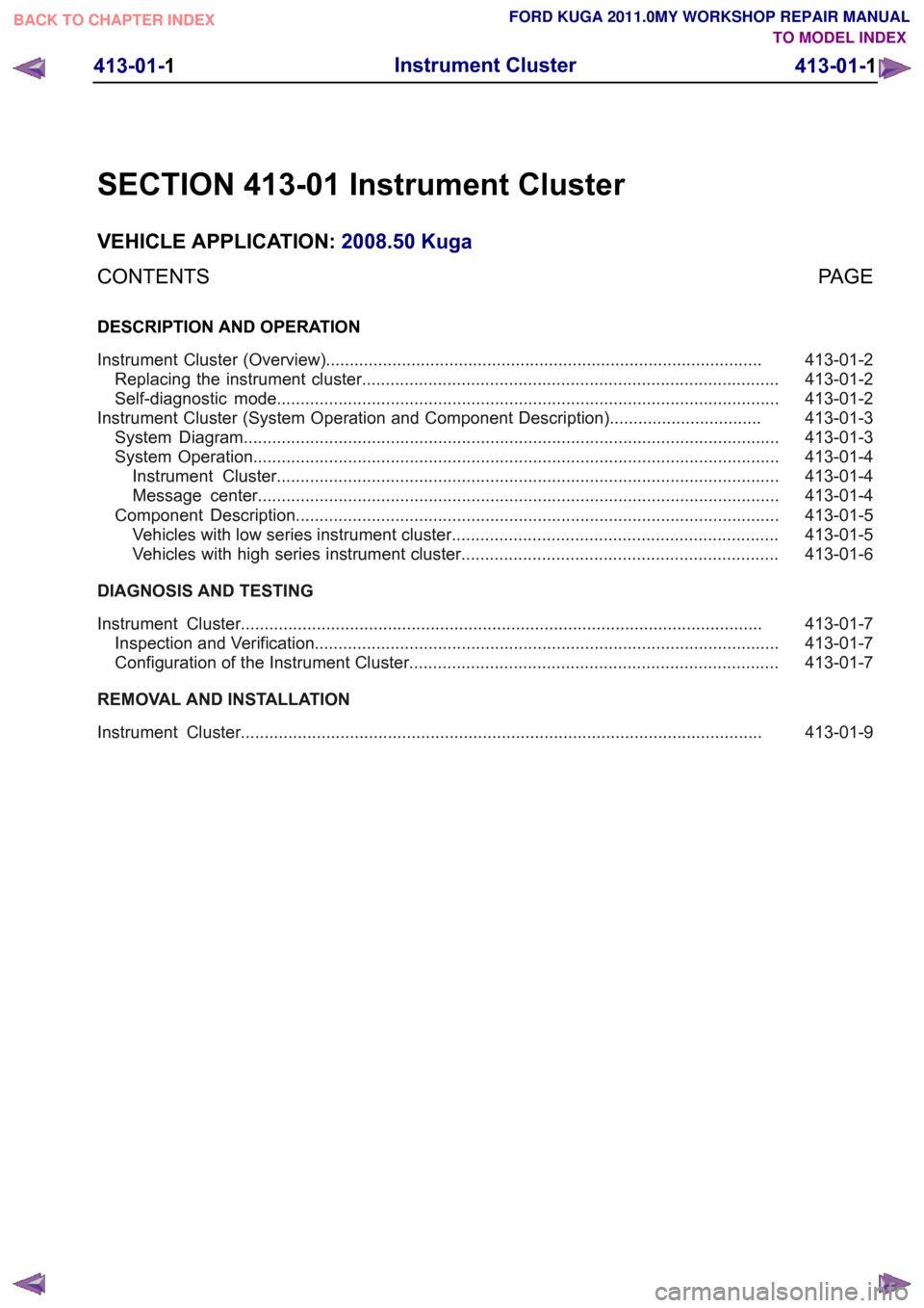
SECTION 413-01 Instrument Cluster
VEHICLE APPLICATION:
2008.50 Kuga
PAGE
CONTENTS
DESCRIPTION AND OPERATION
413-01-2
Instrument Cluster (Overview)............................................................................................
413-01-2
Replacing the instrument cluster........................................................................................
413-01-2
Self-diagnostic mode..........................................................................................................
413-01-3
Instrument Cluster (System Operation and Component Description)................................
413-01-3
System Diagram.................................................................................................................
413-01-4
System Operation...............................................................................................................
413-01-4
Instrument Cluster..........................................................................................................
413-01-4
Message center..............................................................................................................
413-01-5
Component Description......................................................................................................
413-01-5
Vehicles with low series instrument cluster.....................................................................
413-01-6
Vehicles with high series instrument cluster...................................................................
DIAGNOSIS AND TESTING 413-01-7
Instrument Cluster..............................................................................................................
413-01-7
Inspection and Verification..................................................................................................
413-01-7
Configuration of the Instrument Cluster..............................................................................
REMOVAL AND INSTALLATION 413-01-9
Instrument Cluster.............................................................................................................. 413-01-1
Instrument Cluster
413-01-1
.TO MODEL INDEX
BACK TO CHAPTER INDEX
FORD KUGA 2011.0MY WORKSHOP REPAIR MANUAL
Page 190 of 2057
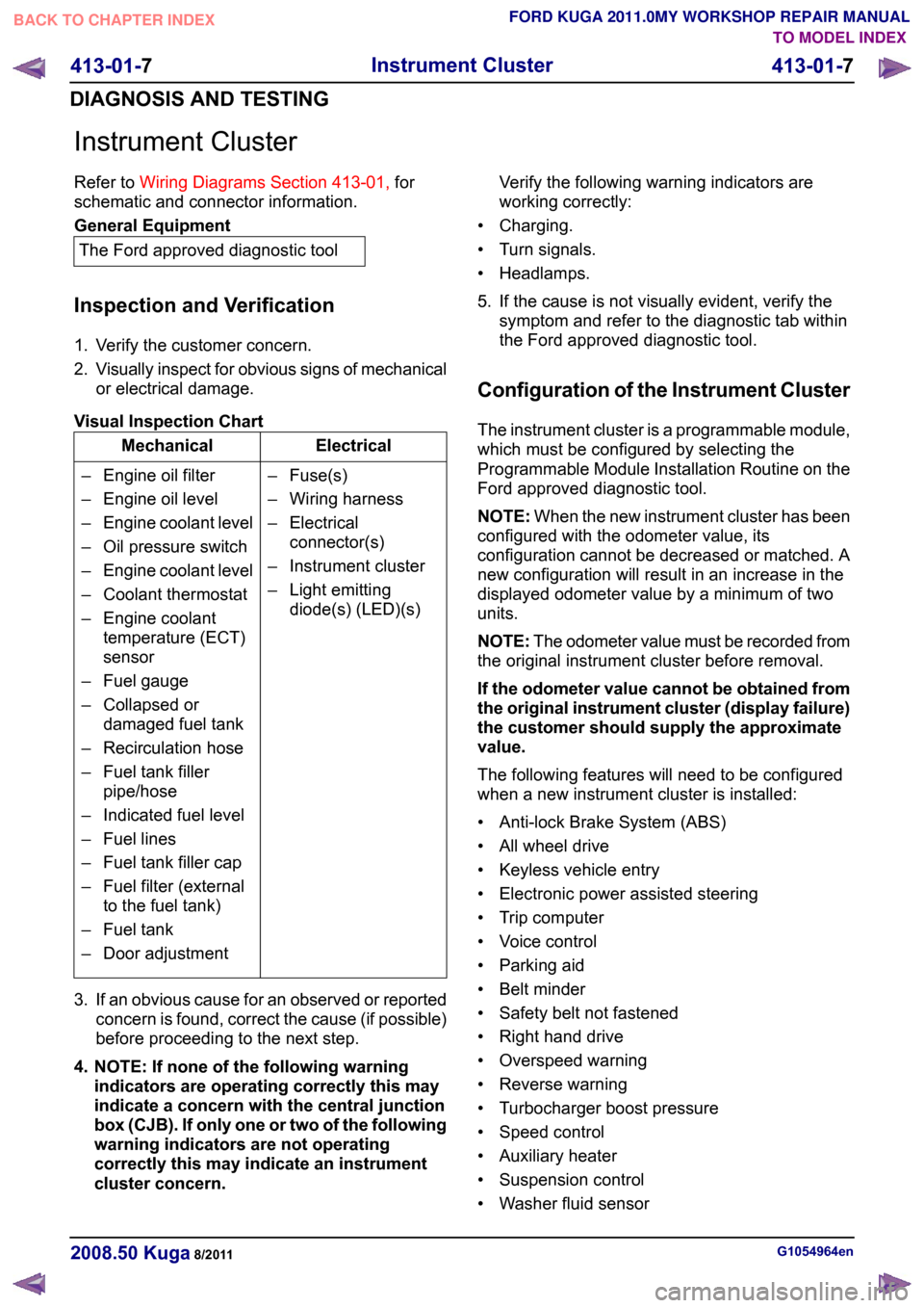
Instrument Cluster
Refer to
Wiring Diagrams Section 413-01, for
schematic and connector information. General Equipment
The Ford approved diagnostic tool
Inspection and Verification
1. Verify the customer concern.
2. Visually inspect for obvious signs of mechanical
or electrical damage.
Visual Inspection Chart Electrical
Mechanical
– Fuse(s)
– Wiring harness
– Electricalconnector(s)
– Instrument cluster
– Light emitting diode(s) (LED)(s)
– Engine oil filter
– Engine oil level
–
Engine coolant level
– Oil pressure switch
– Engine coolant level
– Coolant thermostat
– Engine coolant temperature (ECT)
sensor
– Fuel gauge
– Collapsed or damaged fuel tank
– Recirculation hose
– Fuel tank filler pipe/hose
– Indicated fuel level
– Fuel lines
– Fuel tank filler cap
– Fuel filter (external to the fuel tank)
– Fuel tank
– Door adjustment
3. If an obvious cause for an observed or reported concern is found, correct the cause (if possible)
before proceeding to the next step.
4. NOTE: If none of the following warning indicators are operating correctly this may
indicate a concern with the central junction
box (CJB). If only one or two of the following
warning indicators are not operating
correctly this may indicate an instrument
cluster concern. Verify the following warning indicators are
working correctly:
• Charging.
• Turn signals.
• Headlamps.
5. If the cause is not visually evident, verify the symptom and refer to the diagnostic tab within
the Ford approved diagnostic tool.
Configuration of the Instrument Cluster
The instrument cluster is a programmable module,
which must be configured by selecting the
Programmable Module Installation Routine on the
Ford approved diagnostic tool.
NOTE: When the new instrument cluster has been
configured with the odometer value, its
configuration cannot be decreased or matched. A
new configuration will result in an increase in the
displayed odometer value by a minimum of two
units.
NOTE: The odometer value must be recorded from
the original instrument cluster before removal.
If the odometer value cannot be obtained from
the original instrument cluster (display failure)
the customer should supply the approximate
value.
The following features will need to be configured
when a new instrument cluster is installed:
• Anti-lock Brake System (ABS)
• All wheel drive
• Keyless vehicle entry
• Electronic power assisted steering
• Trip computer
• Voice control
• Parking aid
• Belt minder
• Safety belt not fastened
• Right hand drive
• Overspeed warning
• Reverse warning
• Turbocharger boost pressure
• Speed control
• Auxiliary heater
• Suspension control
• Washer fluid sensor G1054964en
2008.50 Kuga 8/2011 413-01-7
Instrument Cluster
413-01-7
DIAGNOSIS AND TESTINGTO MODEL INDEX
BACK TO CHAPTER INDEX
FORD KUGA 2011.0MY WORKSHOP REPAIR MANUAL
Page 197 of 2057
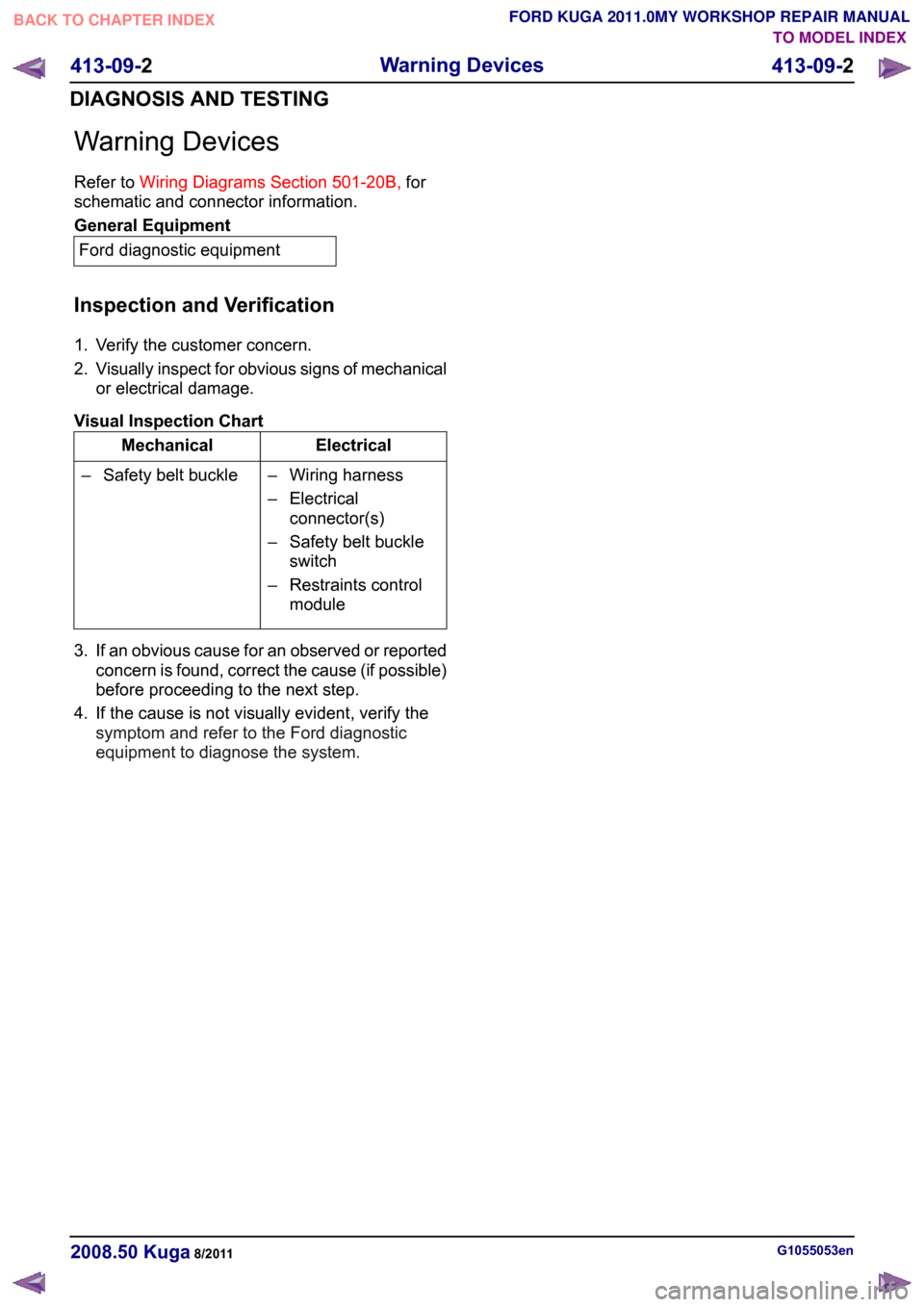
Warning Devices
Refer to
Wiring Diagrams Section 501-20B, for
schematic and connector information. General Equipment
Ford diagnostic equipment
Inspection and Verification
1. Verify the customer concern.
2. Visually inspect for obvious signs of mechanical
or electrical damage.
Visual Inspection Chart Electrical
Mechanical
– Wiring harness
– Electricalconnector(s)
– Safety belt buckle switch
– Restraints control module
– Safety belt buckle
3. If an obvious cause for an observed or reported concern is found, correct the cause (if possible)
before proceeding to the next step.
4. If the cause is not visually evident, verify the symptom and refer to the Ford diagnostic
equipment to diagnose the system. G1055053en
2008.50 Kuga 8/2011 413-09-2
Warning Devices
413-09-2
DIAGNOSIS AND TESTINGTO MODEL INDEX
BACK TO CHAPTER INDEX
FORD KUGA 2011.0MY WORKSHOP REPAIR MANUAL
Page 200 of 2057
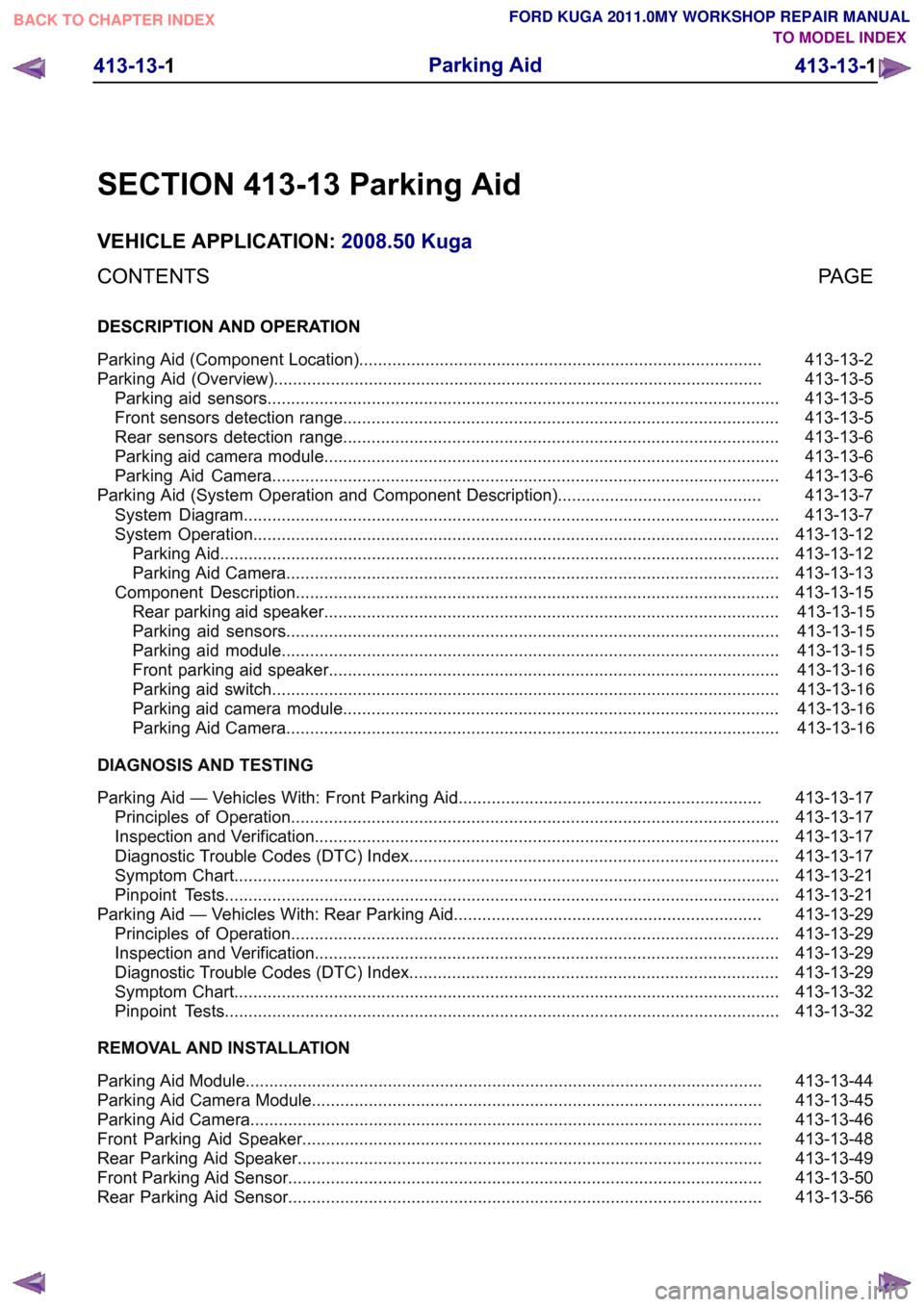
SECTION 413-13 Parking Aid
VEHICLE APPLICATION:
2008.50 Kuga
PAGE
CONTENTS
DESCRIPTION AND OPERATION
413-13-2
Parking Aid (Component Location).....................................................................................
413-13-5
Parking Aid (Overview).......................................................................................................
413-13-5
Parking aid sensors............................................................................................................
413-13-5
Front sensors detection range............................................................................................
413-13-6
Rear sensors detection range............................................................................................
413-13-6
Parking aid camera module................................................................................................
413-13-6
Parking Aid Camera...........................................................................................................
413-13-7
Parking Aid (System Operation and Component Description)...........................................
413-13-7
System Diagram.................................................................................................................
413-13-12
System Operation...............................................................................................................
413-13-12
Parking Aid......................................................................................................................
413-13-13
Parking Aid Camera........................................................................................................
413-13-15
Component Description......................................................................................................413-13-15Rear parking aid speaker................................................................................................
413-13-15Parking aid sensors........................................................................................................
413-13-15Parking aid module.........................................................................................................
413-13-16Front parking aid speaker...............................................................................................
413-13-16Parking aid switch...........................................................................................................
413-13-16Parking aid camera module............................................................................................
413-13-16Parking Aid Camera........................................................................................................
DIAGNOSIS AND TESTING 413-13-17
Parking Aid — Vehicles With: Front Parking Aid................................................................
413-13-17
Principles of Operation.......................................................................................................
413-13-17
Inspection and Verification..................................................................................................
413-13-17
Diagnostic Trouble Codes (DTC) Index..............................................................................
413-13-21
Symptom Chart...................................................................................................................
413-13-21
Pinpoint Tests.....................................................................................................................
413-13-29
Parking Aid — Vehicles With: Rear Parking Aid.................................................................
413-13-29
Principles of Operation.......................................................................................................
413-13-29
Inspection and Verification..................................................................................................
413-13-29
Diagnostic Trouble Codes (DTC) Index..............................................................................
413-13-32
Symptom Chart...................................................................................................................
413-13-32
Pinpoint Tests.....................................................................................................................
REMOVAL AND INSTALLATION 413-13-44
Parking Aid Module.............................................................................................................
413-13-45
Parking Aid Camera Module...............................................................................................
413-13-46
Parking Aid Camera............................................................................................................
413-13-48
Front Parking Aid Speaker.................................................................................................
413-13-49
Rear Parking Aid Speaker..................................................................................................
413-13-50
Front Parking Aid Sensor....................................................................................................
413-13-56
Rear Parking Aid Sensor.................................................................................................... 413-13-1
Parking Aid
413-13-1
.
TO MODEL INDEX
BACK TO CHAPTER INDEX
FORD KUGA 2011.0MY WORKSHOP REPAIR MANUAL
Page 216 of 2057
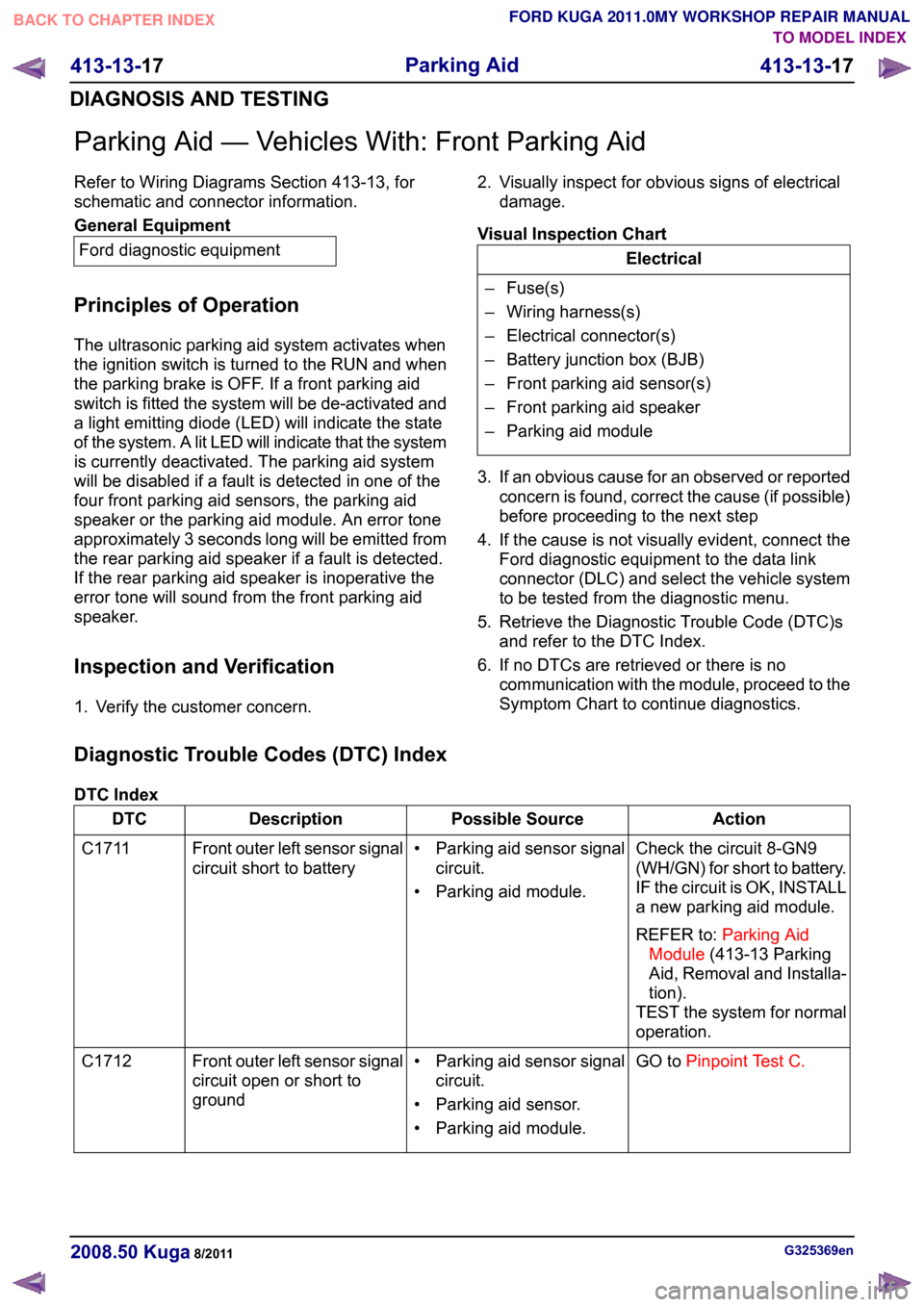
Parking Aid — Vehicles With: Front Parking Aid
Refer to Wiring Diagrams Section 413-13, for
schematic and connector information.
General Equipment
Ford diagnostic equipment
Principles of Operation
The ultrasonic parking aid system activates when
the ignition switch is turned to the RUN and when
the parking brake is OFF. If a front parking aid
switch is fitted the system will be de-activated and
a light emitting diode (LED) will indicate the state
of the system. A lit LED will indicate that the system
is currently deactivated. The parking aid system
will be disabled if a fault is detected in one of the
four front parking aid sensors, the parking aid
speaker or the parking aid module. An error tone
approximately 3 seconds long will be emitted from
the rear parking aid speaker if a fault is detected.
If the rear parking aid speaker is inoperative the
error tone will sound from the front parking aid
speaker.
Inspection and Verification
1. Verify the customer concern. 2. Visually inspect for obvious signs of electrical
damage.
Visual Inspection Chart Electrical
– Fuse(s)
– Wiring harness(s)
– Electrical connector(s)
– Battery junction box (BJB)
– Front parking aid sensor(s)
– Front parking aid speaker
– Parking aid module
3. If an obvious cause for an observed or reported concern is found, correct the cause (if possible)
before proceeding to the next step
4. If the cause is not visually evident, connect the Ford diagnostic equipment to the data link
connector (DLC) and select the vehicle system
to be tested from the diagnostic menu.
5. Retrieve the Diagnostic Trouble Code (DTC)s and refer to the DTC Index.
6. If no DTCs are retrieved or there is no communication with the module, proceed to the
Symptom Chart to continue diagnostics.
Diagnostic Trouble Codes (DTC) Index
DTC Index Action
Possible Source
Description
DTC
Check the circuit 8-GN9
(WH/GN) for short to battery.
IF the circuit is OK, INSTALL
a new parking aid module.
REFER to:Parking Aid
Module (413-13 Parking
Aid, Removal and Installa-
tion).
TEST the system for normal
operation.
• Parking aid sensor signal
circuit.
• Parking aid module.
Front outer left sensor signal
circuit short to battery
C1711
GO toPinpoint Test C.
• Parking aid sensor signal
circuit.
• Parking aid sensor.
• Parking aid module.
Front outer left sensor signal
circuit open or short to
ground
C1712 G325369en
2008.50 Kuga 8/2011 413-13-17
Parking Aid
413-13-17
DIAGNOSIS AND TESTINGTO MODEL INDEX
BACK TO CHAPTER INDEX
FORD KUGA 2011.0MY WORKSHOP REPAIR MANUAL