FORD MAVERICK 2023 Owners Manual
Manufacturer: FORD, Model Year: 2023, Model line: MAVERICK, Model: FORD MAVERICK 2023Pages: 556, PDF Size: 14.79 MB
Page 361 of 556
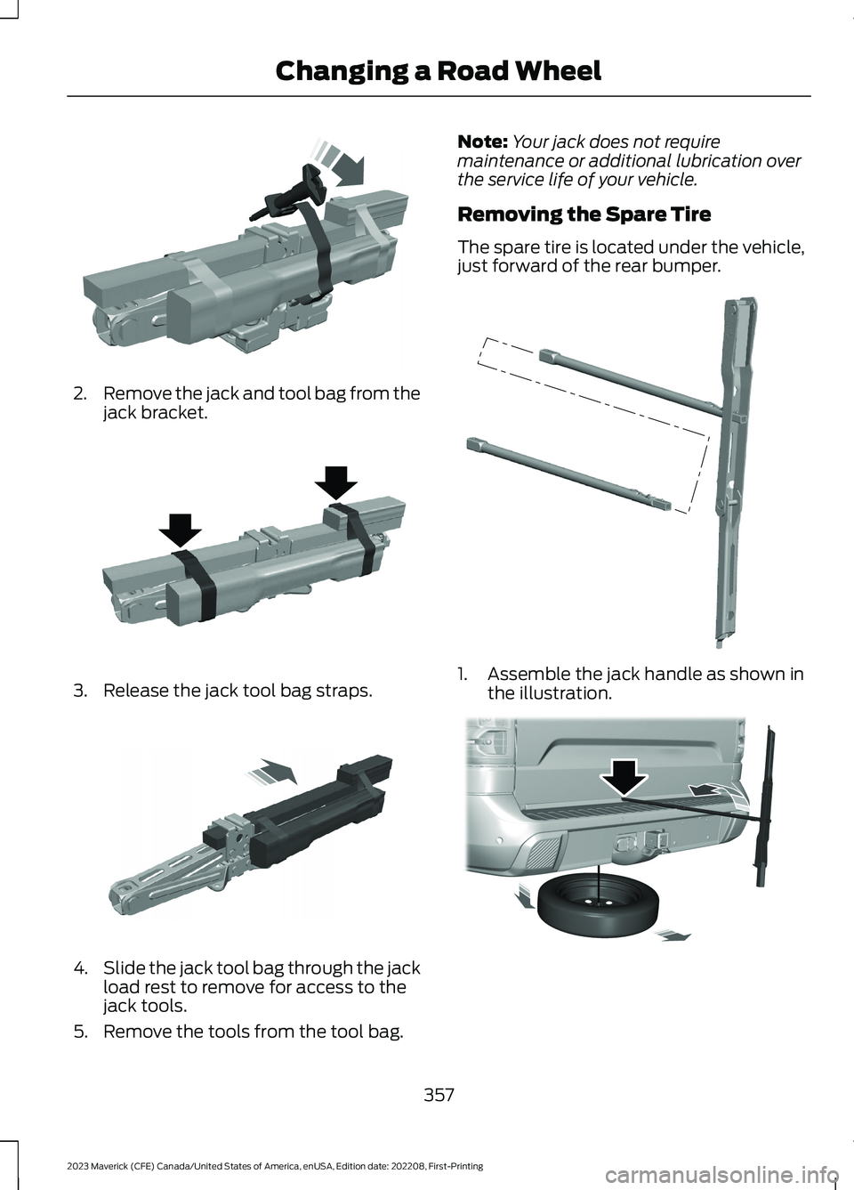
2.Remove the jack and tool bag from thejack bracket.
3.Release the jack tool bag straps.
4.Slide the jack tool bag through the jackload rest to remove for access to thejack tools.
5.Remove the tools from the tool bag.
Note:Your jack does not requiremaintenance or additional lubrication overthe service life of your vehicle.
Removing the Spare Tire
The spare tire is located under the vehicle,just forward of the rear bumper.
1.Assemble the jack handle as shown inthe illustration.
357
2023 Maverick (CFE) Canada/United States of America, enUSA, Edition date: 202208, First-PrintingChanging a Road WheelE352025 E352022 E352033 E352148 E352181
Page 362 of 556
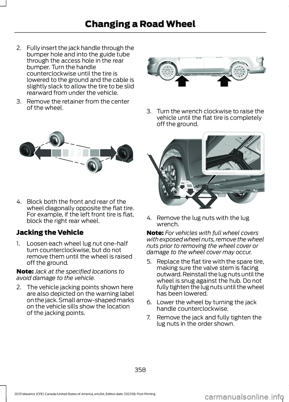
2.Fully insert the jack handle through thebumper hole and into the guide tubethrough the access hole in the rearbumper. Turn the handlecounterclockwise until the tire islowered to the ground and the cable isslightly slack to allow the tire to be slidrearward from under the vehicle.
3.Remove the retainer from the centerof the wheel.
4.Block both the front and rear of thewheel diagonally opposite the flat tire.For example, if the left front tire is flat,block the right rear wheel.
Jacking the Vehicle
1.Loosen each wheel lug nut one-halfturn counterclockwise, but do notremove them until the wheel is raisedoff the ground.
Note:Jack at the specified locations toavoid damage to the vehicle.
2.The vehicle jacking points shown hereare also depicted on the warning labelon the jack. Small arrow-shaped markson the vehicle sills show the locationof the jacking points.
3.Turn the wrench clockwise to raise thevehicle until the flat tire is completelyoff the ground.
4.Remove the lug nuts with the lugwrench.
Note:For vehicles with full wheel coverswith exposed wheel nuts, remove the wheelnuts prior to removing the wheel cover ordamage to the wheel cover may occur.
5.Replace the flat tire with the spare tire,making sure the valve stem is facingoutward. Reinstall the lug nuts until thewheel is snug against the hub. Do notfully tighten the lug nuts until the wheelhas been lowered.
6.Lower the wheel by turning the jackhandle counterclockwise.
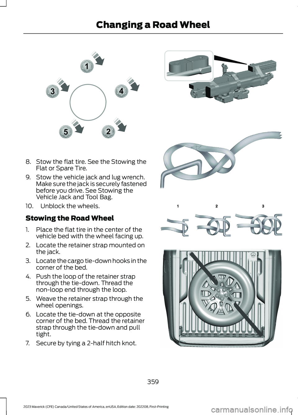
7.Remove the jack and fully tighten thelug nuts in the order shown.
358
2023 Maverick (CFE) Canada/United States of America, enUSA, Edition date: 202208, First-PrintingChanging a Road WheelE175447 E352156 E352182
Page 363 of 556
8.Stow the flat tire. See the Stowing theFlat or Spare Tire.
9.Stow the vehicle jack and lug wrench.Make sure the jack is securely fastenedbefore you drive. See Stowing theVehicle Jack and Tool Bag.
10.Unblock the wheels.
Stowing the Road Wheel
1.Place the flat tire in the center of thevehicle bed with the wheel facing up.
2.Locate the retainer strap mounted onthe jack.
3.Locate the cargo tie-down hooks in thecorner of the bed.
4.Push the loop of the retainer strapthrough the tie-down. Thread thenon-loop end through the loop.
5.Weave the retainer strap through thewheel openings.
6.Locate the tie-down at the oppositecorner of the bed. Thread the retainerstrap through the tie-down and pulltight.
7.Secure by tying a 2-half hitch knot.
359
2023 Maverick (CFE) Canada/United States of America, enUSA, Edition date: 202208, First-PrintingChanging a Road Wheel12345E306781 E355266 E142906 E143746 E355267
Page 364 of 556
Stowing the Spare Tire
Note:Failure to follow the spare tirestowage instructions could result in failureof the cable or loss of the spare tire.
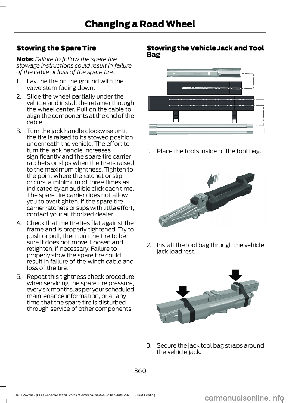
1.Lay the tire on the ground with thevalve stem facing down.
2.Slide the wheel partially under thevehicle and install the retainer throughthe wheel center. Pull on the cable toalign the components at the end of thecable.
3.Turn the jack handle clockwise untilthe tire is raised to its stowed positionunderneath the vehicle. The effort toturn the jack handle increasessignificantly and the spare tire carrierratchets or slips when the tire is raisedto the maximum tightness. Tighten tothe point where the ratchet or slipoccurs, a minimum of three times asindicated by an audible click each time.The spare tire carrier does not allowyou to overtighten. If the spare tirecarrier ratchets or slips with little effort,contact your authorized dealer.
4.Check that the tire lies flat against theframe and is properly tightened. Try topush or pull, then turn the tire to besure it does not move. Loosen andretighten, if necessary. Failure toproperly stow the spare tire couldresult in failure of the winch cable andloss of the tire.
5.Repeat this tightness check procedurewhen servicing the spare tire pressure,every six months, as per your scheduledmaintenance information, or at anytime that the spare tire is disturbedthrough service of other components.
Stowing the Vehicle Jack and ToolBag
1.Place the tools inside of the tool bag.
2.Install the tool bag through the vehiclejack load rest.
3.Secure the jack tool bag straps aroundthe vehicle jack.
360
2023 Maverick (CFE) Canada/United States of America, enUSA, Edition date: 202208, First-PrintingChanging a Road WheelE352149 E352034 E352022
Page 365 of 556
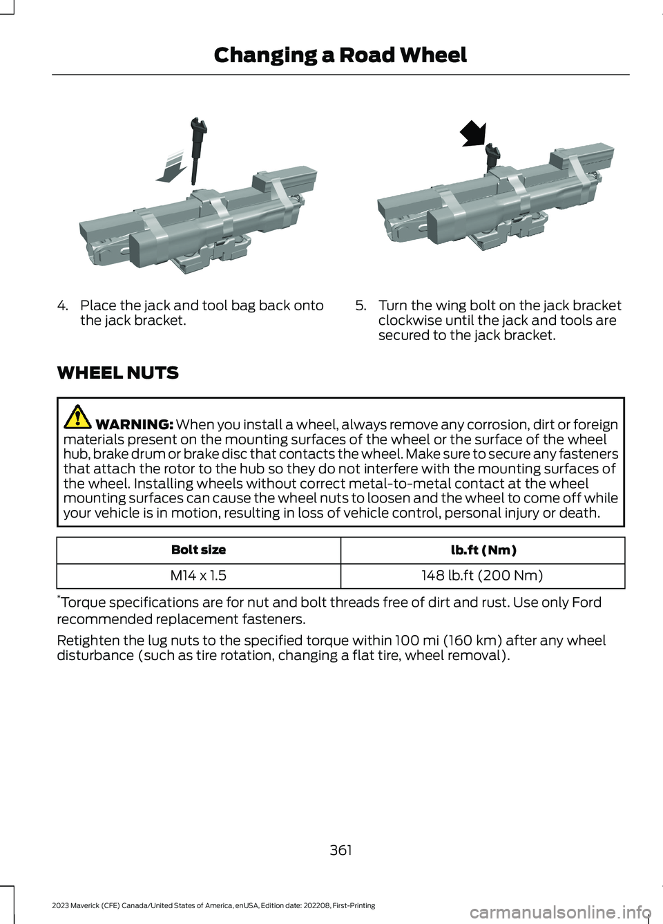
4.Place the jack and tool bag back ontothe jack bracket.5.Turn the wing bolt on the jack bracketclockwise until the jack and tools aresecured to the jack bracket.
WHEEL NUTS
WARNING: When you install a wheel, always remove any corrosion, dirt or foreignmaterials present on the mounting surfaces of the wheel or the surface of the wheelhub, brake drum or brake disc that contacts the wheel. Make sure to secure any fastenersthat attach the rotor to the hub so they do not interfere with the mounting surfaces ofthe wheel. Installing wheels without correct metal-to-metal contact at the wheelmounting surfaces can cause the wheel nuts to loosen and the wheel to come off whileyour vehicle is in motion, resulting in loss of vehicle control, personal injury or death.
lb.ft (Nm)Bolt size
148 lb.ft (200 Nm)M14 x 1.5
*Torque specifications are for nut and bolt threads free of dirt and rust. Use only Fordrecommended replacement fasteners.
Retighten the lug nuts to the specified torque within 100 mi (160 km) after any wheeldisturbance (such as tire rotation, changing a flat tire, wheel removal).
361
2023 Maverick (CFE) Canada/United States of America, enUSA, Edition date: 202208, First-PrintingChanging a Road WheelE352027 E352026
Page 366 of 556
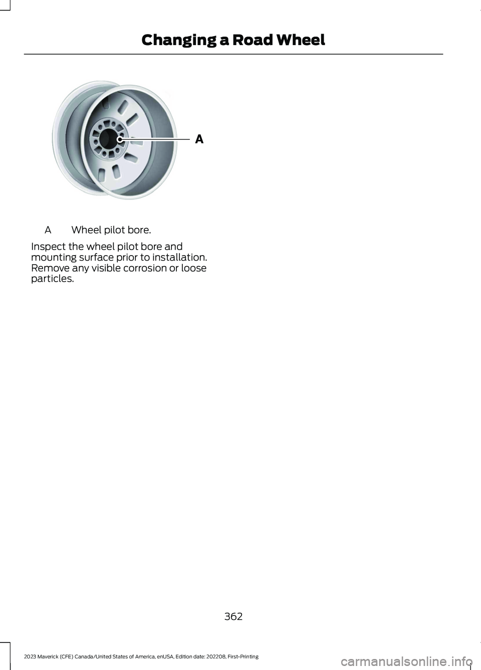
Wheel pilot bore.A
Inspect the wheel pilot bore andmounting surface prior to installation.Remove any visible corrosion or looseparticles.
362
2023 Maverick (CFE) Canada/United States of America, enUSA, Edition date: 202208, First-PrintingChanging a Road WheelE145950
Page 367 of 556
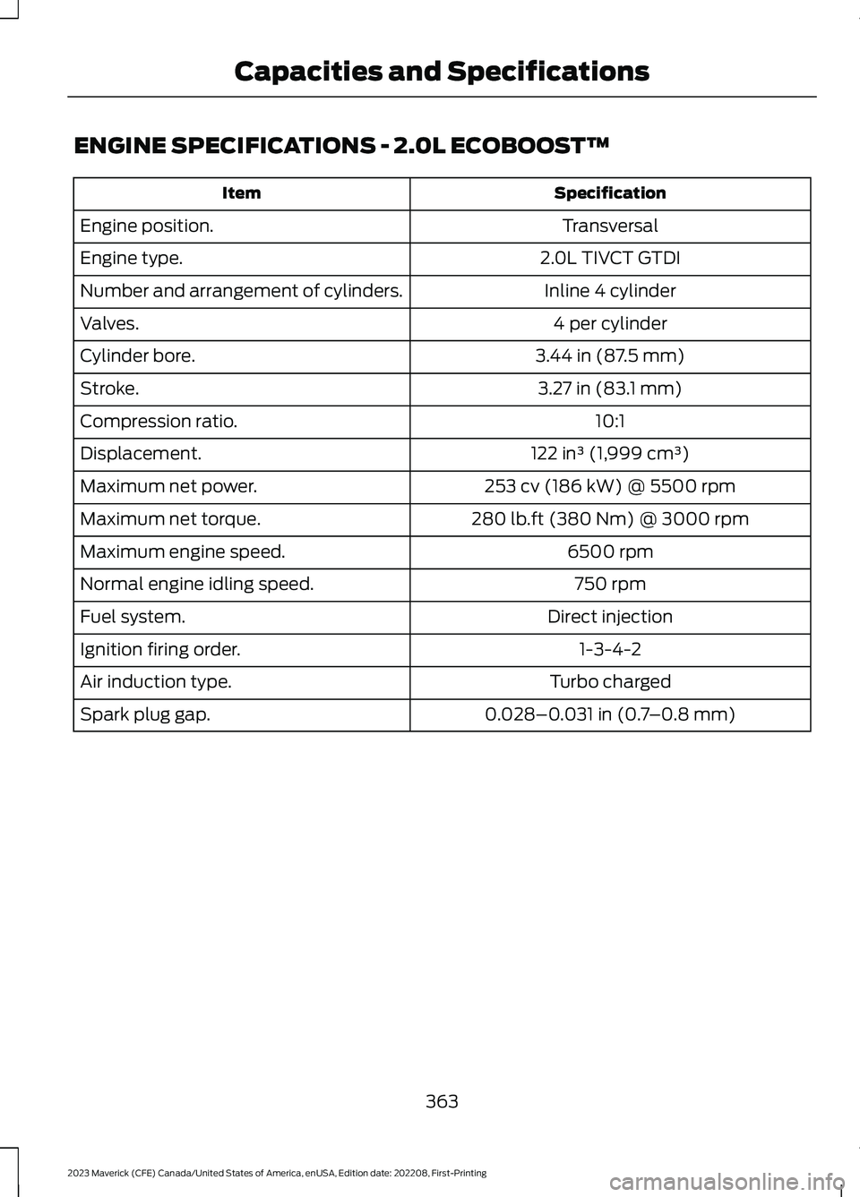
ENGINE SPECIFICATIONS - 2.0L ECOBOOST™
SpecificationItem
TransversalEngine position.
2.0L TIVCT GTDIEngine type.
Inline 4 cylinderNumber and arrangement of cylinders.
4 per cylinderValves.
3.44 in (87.5 mm)Cylinder bore.
3.27 in (83.1 mm)Stroke.
10:1Compression ratio.
122 in³ (1,999 cm³)Displacement.
253 cv (186 kW) @ 5500 rpmMaximum net power.
280 lb.ft (380 Nm) @ 3000 rpmMaximum net torque.
6500 rpmMaximum engine speed.
750 rpmNormal engine idling speed.
Direct injectionFuel system.
1-3-4-2Ignition firing order.
Turbo chargedAir induction type.
0.028–0.031 in (0.7–0.8 mm)Spark plug gap.
363
2023 Maverick (CFE) Canada/United States of America, enUSA, Edition date: 202208, First-PrintingCapacities and Specifications
Page 368 of 556
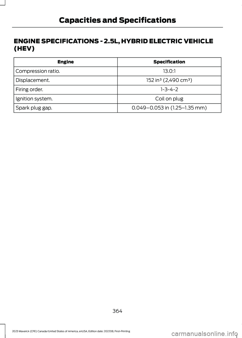
ENGINE SPECIFICATIONS - 2.5L, HYBRID ELECTRIC VEHICLE
(HEV)
SpecificationEngine
13.0:1Compression ratio.
152 in³ (2,490 cm³)Displacement.
1-3-4-2Firing order.
Coil on plugIgnition system.
0.049–0.053 in (1.25–1.35 mm)Spark plug gap.
364
2023 Maverick (CFE) Canada/United States of America, enUSA, Edition date: 202208, First-PrintingCapacities and Specifications
Page 369 of 556
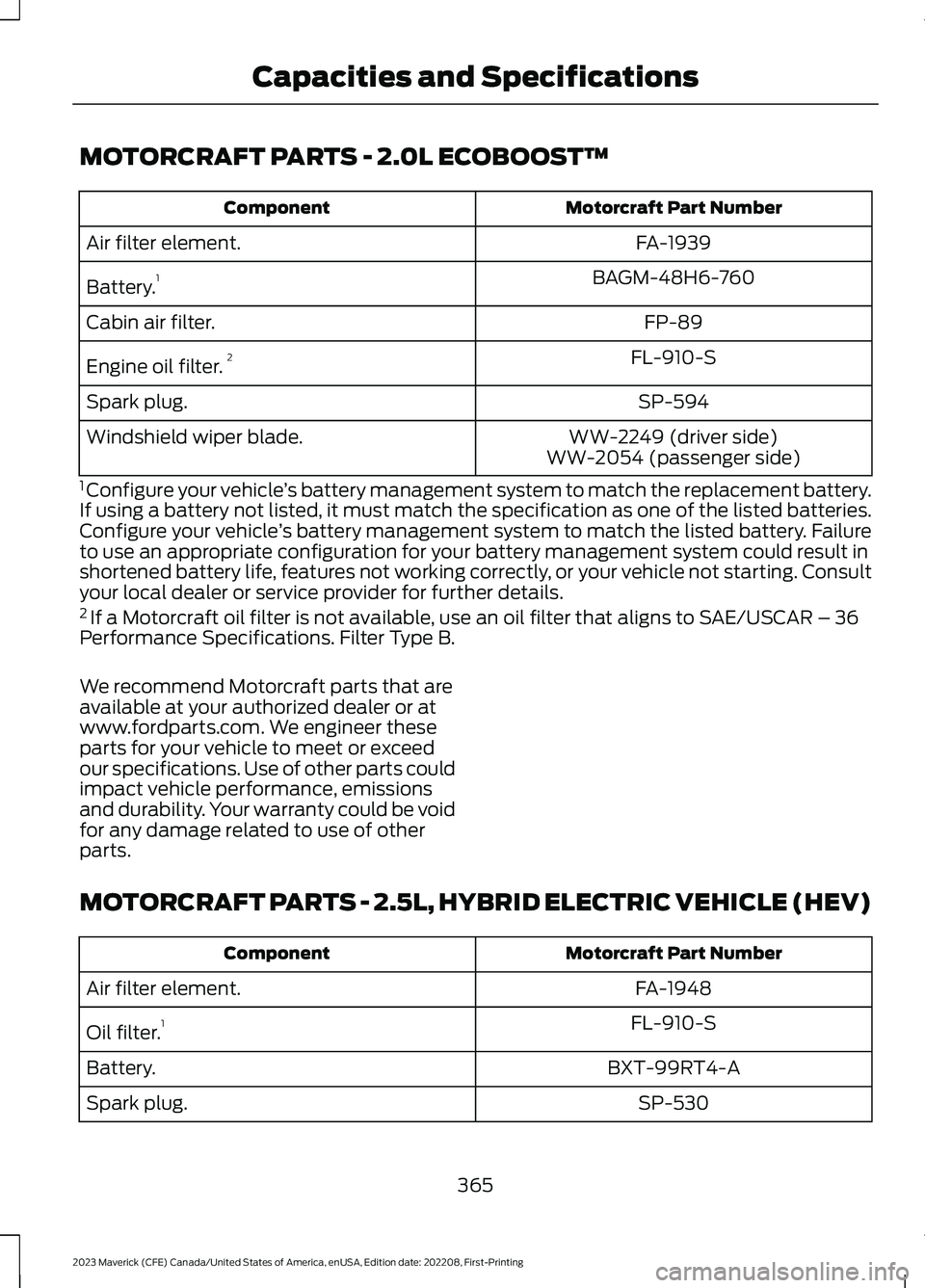
MOTORCRAFT PARTS - 2.0L ECOBOOST™
Motorcraft Part NumberComponent
FA-1939Air filter element.
BAGM-48H6-760Battery.1
FP-89Cabin air filter.
FL-910-SEngine oil filter.2
SP-594Spark plug.
WW-2249 (driver side)Windshield wiper blade.WW-2054 (passenger side)
1 Configure your vehicle’s battery management system to match the replacement battery.If using a battery not listed, it must match the specification as one of the listed batteries.Configure your vehicle’s battery management system to match the listed battery. Failureto use an appropriate configuration for your battery management system could result inshortened battery life, features not working correctly, or your vehicle not starting. Consultyour local dealer or service provider for further details.2 If a Motorcraft oil filter is not available, use an oil filter that aligns to SAE/USCAR – 36Performance Specifications. Filter Type B.
We recommend Motorcraft parts that areavailable at your authorized dealer or atwww.fordparts.com. We engineer theseparts for your vehicle to meet or exceedour specifications. Use of other parts couldimpact vehicle performance, emissionsand durability. Your warranty could be voidfor any damage related to use of otherparts.
MOTORCRAFT PARTS - 2.5L, HYBRID ELECTRIC VEHICLE (HEV)
Motorcraft Part NumberComponent
FA-1948Air filter element.
FL-910-SOil filter.1
BXT-99RT4-ABattery.
SP-530Spark plug.
365
2023 Maverick (CFE) Canada/United States of America, enUSA, Edition date: 202208, First-PrintingCapacities and Specifications
Page 370 of 556
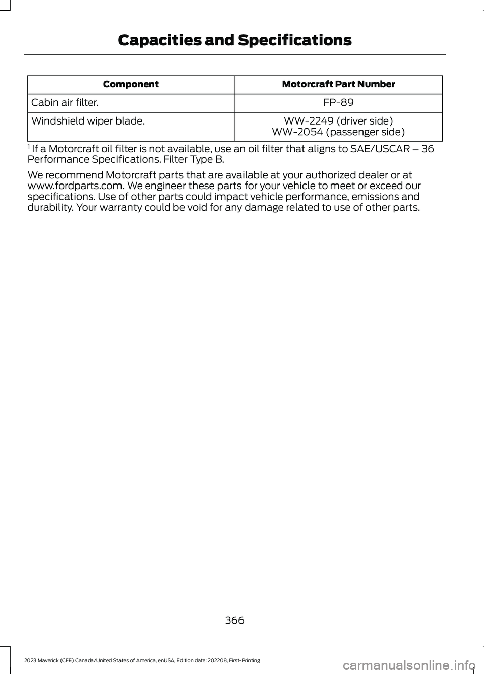
Motorcraft Part NumberComponent
FP-89Cabin air filter.
WW-2249 (driver side)Windshield wiper blade.WW-2054 (passenger side)
1 If a Motorcraft oil filter is not available, use an oil filter that aligns to SAE/USCAR – 36Performance Specifications. Filter Type B.
We recommend Motorcraft parts that are available at your authorized dealer or atwww.fordparts.com. We engineer these parts for your vehicle to meet or exceed ourspecifications. Use of other parts could impact vehicle performance, emissions anddurability. Your warranty could be void for any damage related to use of other parts.
366
2023 Maverick (CFE) Canada/United States of America, enUSA, Edition date: 202208, First-PrintingCapacities and Specifications