warning FORD MONDEO 1993 Service Owner's Manual
[x] Cancel search | Manufacturer: FORD, Model Year: 1993, Model line: MONDEO, Model: FORD MONDEO 1993Pages: 279, PDF Size: 12.71 MB
Page 62 of 279
the gasket, move the pump into the correct
position, and tighten its bolts to the specified
torque wrench setting.
14Check that the pump is correctly located;
if necessary, unbolt it again, and repeat the
full procedure to ensure that the pump is
correctly aligned.
15Fit a new crankshaft right-hand oil seal
(see Section 20).
16Using grease to stick the gasket in place
on the pump, refit the pick-up/strainer pipe,
tightening its screws and nut to their specified
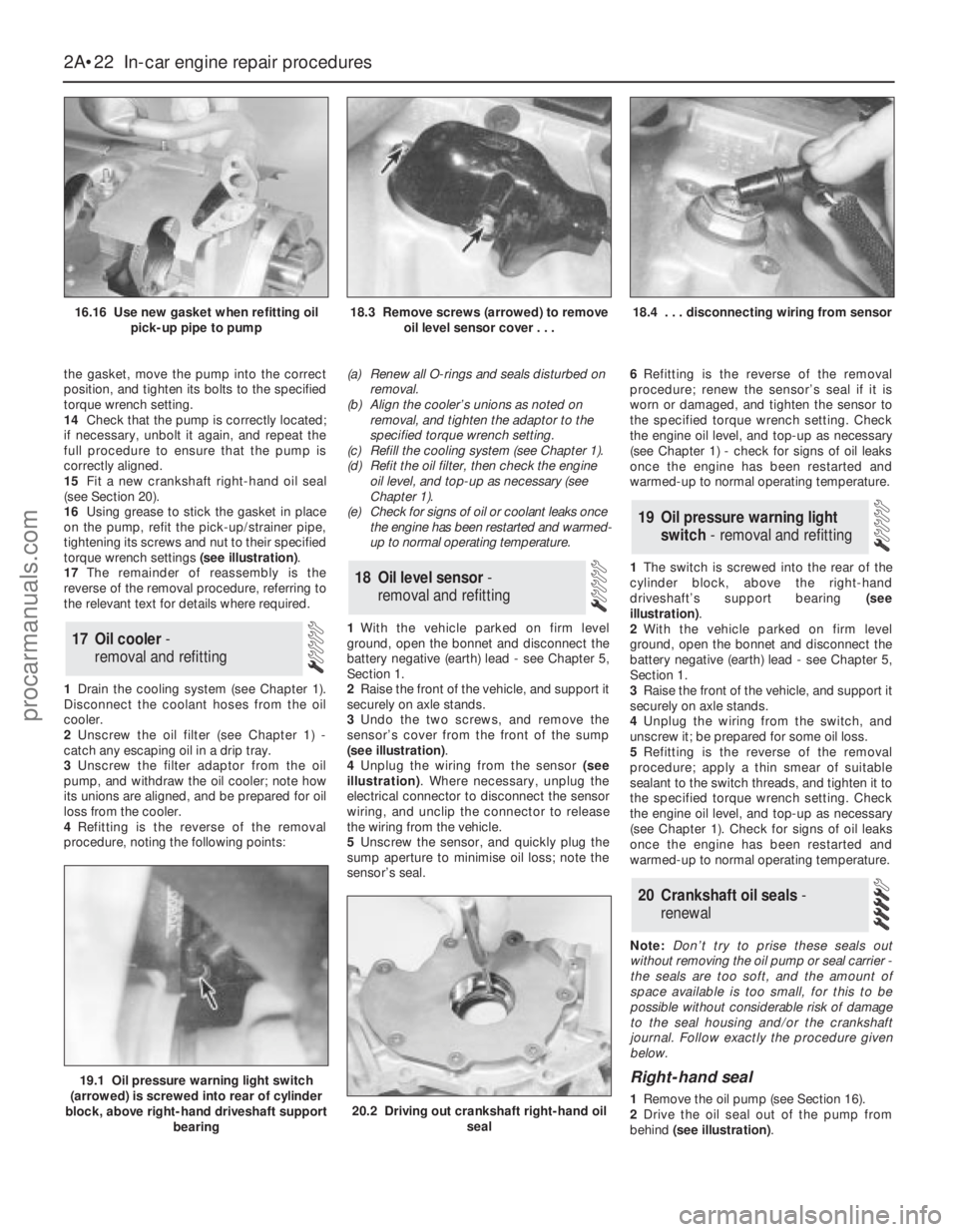
torque wrench settings (see illustration).
17The remainder of reassembly is the
reverse of the removal procedure, referring to
the relevant text for details where required.
1Drain the cooling system (see Chapter 1).
Disconnect the coolant hoses from the oil
cooler.
2Unscrew the oil filter (see Chapter 1) -
catch any escaping oil in a drip tray.
3Unscrew the filter adaptor from the oil
pump, and withdraw the oil cooler; note how
its unions are aligned, and be prepared for oil
loss from the cooler.
4Refitting is the reverse of the removal
procedure, noting the following points:(a) Renew all O-rings and seals disturbed on
removal.
(b) Align the cooler’s unions as noted on
removal, and tighten the adaptor to the
specified torque wrench setting.
(c) Refill the cooling system (see Chapter 1).
(d) Refit the oil filter, then check the engine
oil level, and top-up as necessary (see
Chapter 1).
(e) Check for signs of oil or coolant leaks once
the engine has been restarted and warmed-
up to normal operating temperature.
1With the vehicle parked on firm level
ground, open the bonnet and disconnect the
battery negative (earth) lead - see Chapter 5,
Section 1.
2Raise the front of the vehicle, and support it
securely on axle stands.
3Undo the two screws, and remove the
sensor’s cover from the front of the sump
(see illustration).
4Unplug the wiring from the sensor (see
illustration). Where necessary, unplug the
electrical connector to disconnect the sensor
wiring, and unclip the connector to release
the wiring from the vehicle.
5Unscrew the sensor, and quickly plug the
sump aperture to minimise oil loss; note the
sensor’s seal.6Refitting is the reverse of the removal
procedure; renew the sensor’s seal if it is
worn or damaged, and tighten the sensor to
the specified torque wrench setting. Check
the engine oil level, and top-up as necessary
(see Chapter 1) - check for signs of oil leaks
once the engine has been restarted and
warmed-up to normal operating temperature.
1The switch is screwed into the rear of the
cylinder block, above the right-hand
driveshaft’s support bearing (see
illustration).
2With the vehicle parked on firm level
ground, open the bonnet and disconnect the
battery negative (earth) lead - see Chapter 5,
Section 1.
3Raise the front of the vehicle, and support it
securely on axle stands.
4Unplug the wiring from the switch, and
unscrew it; be prepared for some oil loss.
5Refitting is the reverse of the removal
procedure; apply a thin smear of suitable
sealant to the switch threads, and tighten it to
the specified torque wrench setting. Check
the engine oil level, and top-up as necessary
(see Chapter 1). Check for signs of oil leaks
once the engine has been restarted and
warmed-up to normal operating temperature.
Note:Don’t try to prise these seals out
without removing the oil pump or seal carrier -
the seals are too soft, and the amount of
space available is too small, for this to be
possible without considerable risk of damage
to the seal housing and/or the crankshaft
journal. Follow exactly the procedure given
below.
Right-hand seal
1Remove the oil pump (see Section 16).
2Drive the oil seal out of the pump from
behind (see illustration).
20 Crankshaft oil seals -
renewal
19 Oil pressure warning light
switch - removal and refitting
18 Oil level sensor-
removal and refitting
17 Oil cooler -
removal and refitting
2A•22 In-car engine repair procedures
16.16 Use new gasket when refitting oil
pick-up pipe to pump18.3 Remove screws (arrowed) to remove
oil level sensor cover . . .18.4 . . . disconnecting wiring from sensor
19.1 Oil pressure warning light switch
(arrowed) is screwed into rear of cylinder
block, above right-hand driveshaft support
bearing
20.2 Driving out crankshaft right-hand oil
seal
procarmanuals.com
Page 64 of 279
Removal
1Remove the transmission (see the relevant
Part of Chapter 7). Now is a good time to
check components such as oil seals and
renew them if necessary.
2Where appropriate, remove the clutch
(Chapter 8). Now is a good time to check or
renew the clutch components and pilot
bearing.
3Use a centre-punch or paint to make
alignment marks on the flywheel/driveplate
and crankshaft, to ensure correct alignment
during refitting.
4Prevent the flywheel/driveplate from
turning by locking the ring gear teeth, or by
bolting a strap between the flywheel/
driveplate and the cylinder block/
crankcase. Slacken the bolts evenly until all
are free.
5Remove each bolt in turn, and ensure that
new replacements are obtained for
reassembly; these bolts are subjected to
severe stresses, and so must be renewed,
regardless of their apparent condition,
whenever they are disturbed.
6Noting the reinforcing plate (automatic
transmission-equipped models only),
withdraw the flywheel/driveplate; do not drop
it - it is very heavy.
Inspection
7Clean the flywheel/driveplate to remove
grease and oil. Inspect the surface for cracks,
rivet grooves, burned areas and score marks.
Light scoring can be removed with emery
cloth. Check for cracked and broken ring gear
teeth. Lay the flywheel/driveplate on a flat
surface, and use a straight edge to check for
warpage.
8Clean and inspect the mating surfaces of
the flywheel/driveplate and the crankshaft. If
the crankshaft left-hand seal is leaking, renew
it (see Section 20) before refitting the
flywheel/driveplate.
9While the flywheel/driveplate is removed,clean carefully its inboard (right-hand) face,
particularly the recesses which serve as the
reference points for the crankshaft
speed/position sensor. Clean the sensor’s tip,
and check that the sensor is securely
fastened.
Refitting
10On refitting, ensure that the
engine/transmission adaptor plate is in place
(where necessary), then fit the
flywheel/driveplate to the crankshaft so that
all bolt holes align - it will fit only one way -
check this using the marks made on removal.
Do not forget the reinforcing plate (where
fitted).
11Lock the flywheel/driveplate by the
method used on dismantling. Working in a
diagonal sequence to tighten them evenly,
and increasing to the final amount in two or
three stages, tighten the new bolts to the
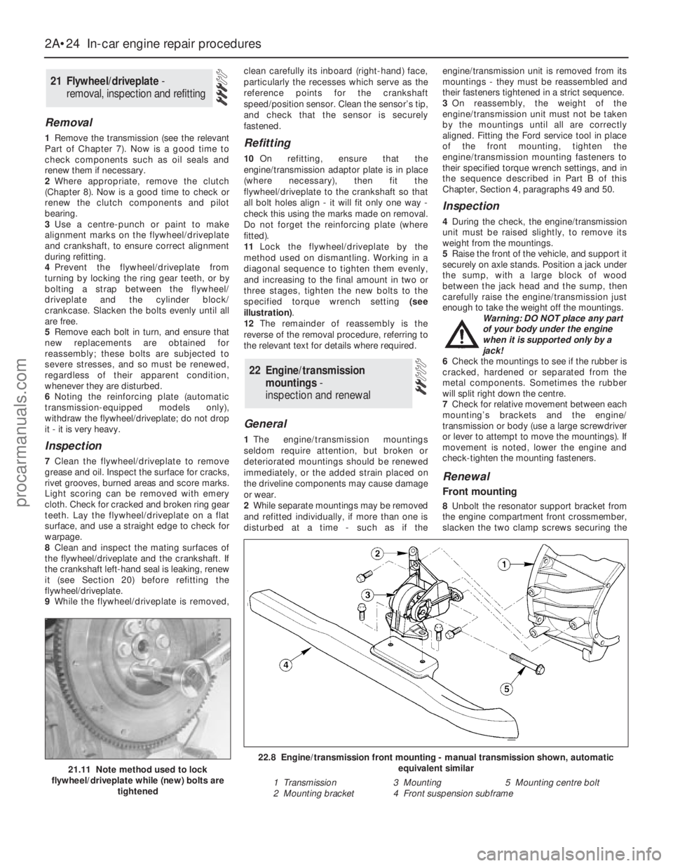
specified torque wrench setting (see
illustration).
12The remainder of reassembly is the
reverse of the removal procedure, referring to
the relevant text for details where required.
General
1The engine/transmission mountings
seldom require attention, but broken or
deteriorated mountings should be renewed
immediately, or the added strain placed on
the driveline components may cause damage
or wear.
2While separate mountings may be removed
and refitted individually, if more than one is
disturbed at a time - such as if theengine/transmission unit is removed from its
mountings - they must be reassembled and
their fasteners tightened in a strict sequence.
3On reassembly, the weight of the
engine/transmission unit must not be taken
by the mountings until all are correctly
aligned. Fitting the Ford service tool in place
of the front mounting, tighten the
engine/transmission mounting fasteners to
their specified torque wrench settings, and in
the sequence described in Part B of this
Chapter, Section 4, paragraphs 49 and 50.
Inspection
4During the check, the engine/transmission
unit must be raised slightly, to remove its
weight from the mountings.
5Raise the front of the vehicle, and support it
securely on axle stands. Position a jack under
the sump, with a large block of wood
between the jack head and the sump, then
carefully raise the engine/transmission just
enough to take the weight off the mountings.
Warning: DO NOT place any part
of your body under the engine
when it is supported only by a
jack!
6Check the mountings to see if the rubber is
cracked, hardened or separated from the
metal components. Sometimes the rubber
will split right down the centre.
7Check for relative movement between each
mounting’s brackets and the engine/
transmission or body (use a large screwdriver
or lever to attempt to move the mountings). If
movement is noted, lower the engine and
check-tighten the mounting fasteners.
Renewal
Front mounting
8Unbolt the resonator support bracket from
the engine compartment front crossmember,
slacken the two clamp screws securing the
22 Engine/transmission
mountings -
inspection and renewal
21 Flywheel/driveplate -
removal, inspection and refitting
2A•24 In-car engine repair procedures
21.11 Note method used to lock
flywheel/driveplate while (new) bolts are
tightened
22.8 Engine/transmission front mounting - manual transmission shown, automatic
equivalent similar
1 Transmission 3 Mounting 5 Mounting centre bolt
2 Mounting bracket 4 Front suspension subframe
procarmanuals.com
Page 70 of 279
safely and with relative ease, and which may
have to be hired or borrowed, includes (in
addition to the engine hoist) a heavy-duty trolley
jack, a strong pair of axle stands, some wooden
blocks, and an engine dolly (a low, wheeled
platform capable of taking the weight of the
engine/transmission, so that it can be moved
easily when on the ground). A complete set of
spanners and sockets (as described in the front
of this manual) will obviously be needed,
together with plenty of rags and cleaning
solvent for mopping-up spilled oil, coolant and
fuel. If the hoist is to be hired, make sure that
you arrange for it in advance, and perform all of
the operations possible without it beforehand.
This will save you money and time.
Plan for the vehicle to be out of use for
quite a while. A machine shop will be required
to perform some of the work which the do-it-
yourselfer can’t accomplish without special
equipment. These establishments often have
a busy schedule, so it would be a good idea
to consult them before removing the engine,
to accurately estimate the amount of time
required to rebuild or repair components that
may need work.
Always be extremely careful when removing
and installing the engine/transmission.
Serious injury can result from careless
actions. By planning ahead and taking your
time, the job (although a major task) can be
accomplished successfully.
Warning: Petrol is extremely
flammable, so take extra
precautions when disconnecting
any part of the fuel system. Don’t
smoke, or allow naked flames or bare light
bulbs in or near the work area, and don’t
work in a garage where a natural gas
appliance (such as a clothes dryer or water
heater) is installed. If you spill petrol on
your skin, rinse it off immediately. Have a
fire extinguisher rated for petrol fires
handy, and know how to use it.Note: Read through the entire Section, as well
as reading the advice in the preceding Section,
before beginning this procedure. The engine
and transmission are removed as a unit,
lowered to the ground and removed from
underneath, then separated outside the vehicle.
Removal
1Park the vehicle on firm, level ground, apply
the handbrake firmly, and slacken the nuts
securing both front roadwheels.
2Relieve the fuel system pressure (see
Chapter 4).
3Disconnect the battery negative (earth) lead
- see Chapter 5, Section 1. For better access
the battery may be removed completely (see
Chapter 5).
4Place protective covers on the wings and
engine compartment front crossmember, then
remove the bonnet (see Chapter 11).
5Whenever you disconnect any vacuum
lines, coolant and emissions hoses, wiring
loom connectors, earth straps and fuel lines
as part of the following procedure, always
label them clearly, so that they can be
correctly reassembled.
6Unplug the two electrical connectors,disconnect the vacuum hose (where fitted)
and disconnect the crankcase breather hose
from the cylinder head cover, then remove the
complete air cleaner assembly, with the air
mass meter, the resonator and the plenum
chamber (see Chapter 4).
7Equalise the pressure in the fuel tank by
removing the filler cap, then undo the fuel
feed and return lines connecting the engine to
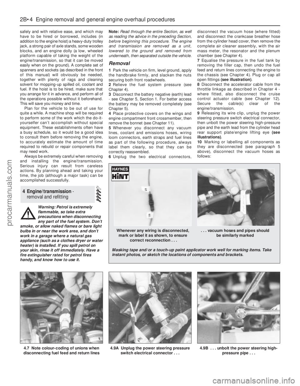
the chassis (see Chapter 4). Plug or cap all
open fittings (see illustration).
8Disconnect the accelerator cable from the
throttle linkage as described in Chapter 4 -
where fitted, also disconnect the cruise
control actuator cable (see Chapter 12).
Secure the cable(s) clear of the
engine/transmission.
9Releasing its wire clip, unplug the power
steering pressure switch electrical connector,
then unbolt the power steering high-pressure
pipe and the earth lead from the cylinder head
rear support plate/engine lifting eye (see
illustrations).
10Marking or labelling all components as
they are disconnected (see paragraph 5
above), disconnect the vacuum hoses as
follows:
4 Engine/transmission -
removal and refitting
2B•4 Engine removal and general engine overhaul procedures
4.7 Note colour-coding of unions when
disconnecting fuel feed and return lines4.9A Unplug the power steering pressure
switch electrical connector . . .4.9B . . . unbolt the power steering high-
pressure pipe . . .
Whenever any wiring is disconnected, . . . vacuum hoses and pipes should
mark or label it as shown, to ensure be similarly marked
correct reconnection . . .
Masking tape and/or a touch-up paint applicator work well for marking items. Take
instant photos, or sketch the locations of components and brackets.
procarmanuals.com
Page 72 of 279
inner wing panel, release the engine
wiring loom and refit the power steering
fluid reservoir.
(g) Secure the engine wiring loom neatly to
the engine/transmission so that it cannot
be damaged as the unit is removed from
the vehicle.
14Unbolt both parts of the exhaust manifold
heat shield; unclip the coolant hose to allow
the upper part to be withdrawn.
15Remove the auxiliary drivebelt (see
Chapter 1).
16Unbolt the power steering pump (see
Chapter 10); secure it as far as possible
(without disconnecting the system’s hoses)
clear of the engine/transmission.
17Raise the vehicle and support it securely
on axle stands, then remove the front
roadwheels. Drain the cooling system and (if
the engine is to be dismantled) drain the
engine oil and remove the oil filter (see
Chapter 1). Also drain the transmission as
described in the relevant Part of Chapter 7.
18Withdraw the lower part of the exhaust
manifold heat shield.
19Unscrew the nuts to disconnect the
exhaust system front downpipe from the
manifold, then unhook all the system’s rubber
mountings and withdraw the complete
exhaust system from under the vehicle (see
Chapter 4 for details).
20Where the vehicle is fitted with manual
transmission, mark their positions, then
disconnect the gearchange linkage and
transmission support rods from the rear of the
transmission. Unscrew the retaining nuts, and
withdraw the gear linkage heat shield from the
underbody. Unbolt the rear end of the linkage
from the underbody, swivel the linkage around
to the rear, and tie it to the underbody (see
Chapter 7, Part A, for details).
21Disconnect both anti-roll bar links from
their respective suspension strut - note the
flexible brake hose bracket attached to each
link stud - and both track rod ends from their
steering knuckles. Unfasten the clamp bolt
securing each front suspension lower arm
balljoint to its steering knuckle (see Chap-
ter 10 for details). Check that both balljoints
can be released from the knuckle assemblies
when required, but leave them in place for thetime being, secured by the clamp bolts if
necessary.
22Where the vehicle is fitted with air
conditioning, unbolt the accumulator/
dehydrator from the subframe; secure it as far
as possible (without disconnecting the
system’s hoses) clear of the engine/
transmission.
Warning: Do not disconnect the
refrigerant hoses.
23Unbolt the steering gear from the
subframe; if the bolts are not accessible from
above, a Ford service tool will be required to
reach them from underneath the vehicle (see
Chapter 10 for details).
24Unscrew the two bolts securing the power
steering system pipes to the right-hand side
of the subframe.
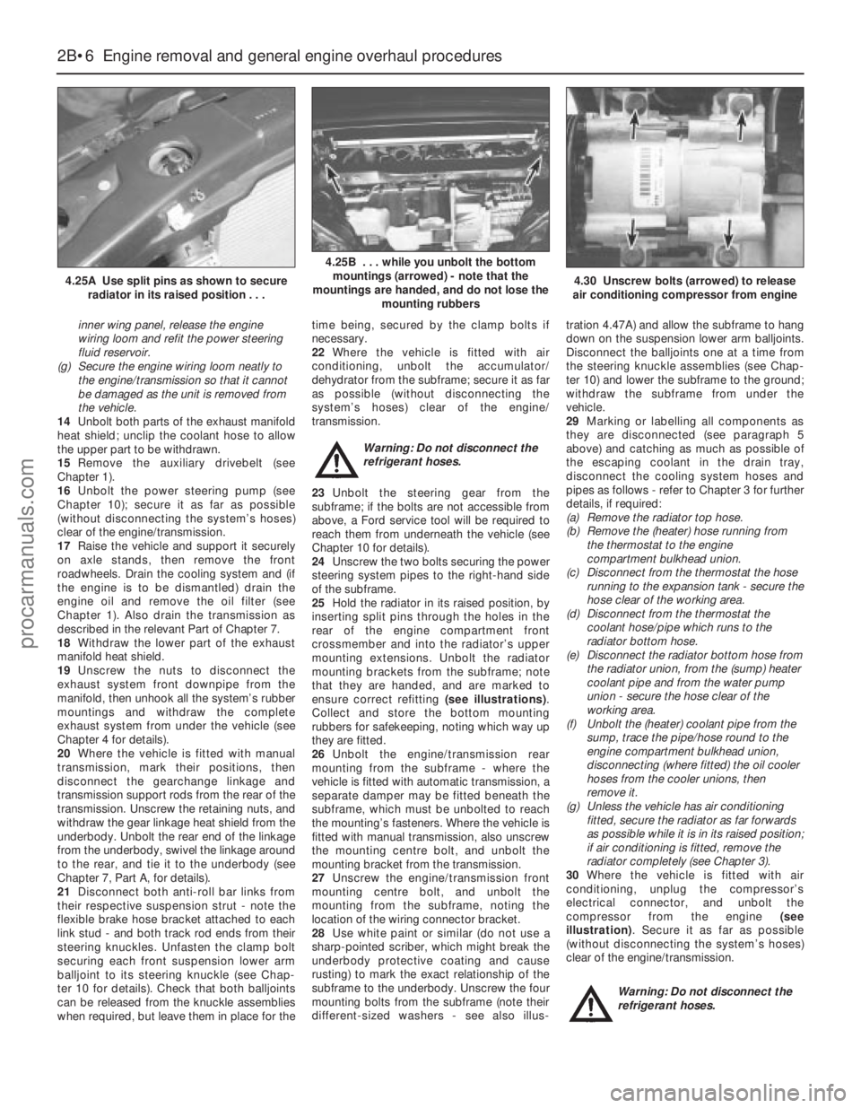
25Hold the radiator in its raised position, by
inserting split pins through the holes in the
rear of the engine compartment front
crossmember and into the radiator’s upper
mounting extensions. Unbolt the radiator
mounting brackets from the subframe; note
that they are handed, and are marked to
ensure correct refitting (see illustrations).
Collect and store the bottom mounting
rubbers for safekeeping, noting which way up
they are fitted.
26Unbolt the engine/transmission rear
mounting from the subframe - where the
vehicle is fitted with automatic transmission, a
separate damper may be fitted beneath the
subframe, which must be unbolted to reach
the mounting’s fasteners. Where the vehicle is
fitted with manual transmission, also unscrew
the mounting centre bolt, and unbolt the
mounting bracket from the transmission.
27Unscrew the engine/transmission front
mounting centre bolt, and unbolt the
mounting from the subframe, noting the
location of the wiring connector bracket.
28Use white paint or similar (do not use a
sharp-pointed scriber, which might break the
underbody protective coating and cause
rusting) to mark the exact relationship of the
subframe to the underbody. Unscrew the four
mounting bolts from the subframe (note their
different-sized washers - see also illus-tration 4.47A) and allow the subframe to hang
down on the suspension lower arm balljoints.
Disconnect the balljoints one at a time from
the steering knuckle assemblies (see Chap-
ter 10) and lower the subframe to the ground;
withdraw the subframe from under the
vehicle.
29Marking or labelling all components as
they are disconnected (see paragraph 5
above) and catching as much as possible of
the escaping coolant in the drain tray,
disconnect the cooling system hoses and
pipes as follows - refer to Chapter 3 for further
details, if required:
(a) Remove the radiator top hose.
(b) Remove the (heater) hose running from
the thermostat to the engine
compartment bulkhead union.
(c) Disconnect from the thermostat the hose
running to the expansion tank - secure the
hose clear of the working area.
(d) Disconnect from the thermostat the
coolant hose/pipe which runs to the
radiator bottom hose.
(e) Disconnect the radiator bottom hose from
the radiator union, from the (sump) heater
coolant pipe and from the water pump
union - secure the hose clear of the
working area.
(f) Unbolt the (heater) coolant pipe from the
sump, trace the pipe/hose round to the
engine compartment bulkhead union,
disconnecting (where fitted) the oil cooler
hoses from the cooler unions, then
remove it.
(g) Unless the vehicle has air conditioning
fitted, secure the radiator as far forwards
as possible while it is in its raised position;
if air conditioning is fitted, remove the
radiator completely (see Chapter 3).
30Where the vehicle is fitted with air
conditioning, unplug the compressor’s
electrical connector, and unbolt the
compressor from the engine (see
illustration). Secure it as far as possible
(without disconnecting the system’s hoses)
clear of the engine/transmission.
Warning: Do not disconnect the
refrigerant hoses.
2B•6 Engine removal and general engine overhaul procedures
4.25A Use split pins as shown to secure
radiator in its raised position . . .
4.25B . . . while you unbolt the bottom
mountings (arrowed) - note that the
mountings are handed, and do not lose the
mounting rubbers
4.30 Unscrew bolts (arrowed) to release
air conditioning compressor from engine
procarmanuals.com
Page 73 of 279
31Where the vehicle is fitted with manual
transmission, disconnect the driveshafts from
the transmission as follows, referring to
Chapter 8 for further details when required:
(a) Unscrew the nuts securing the right-hand
driveshaft support bearing, and withdraw
the heat shield.
(b) Pull the right-hand driveshaft out of the
transmission; be prepared to catch any
spilt oil.
(c) Secure the driveshaft clear of the
engine/transmission - remember that the
unit is to be lowered out of the vehicle -
and ensure that the inner joint is not
turned through more than 18°.
(d) Prise the left-hand driveshaft out of the
transmission - again, be prepared for oil
spillage. Secure the driveshaft clear of the
engine/transmission, and ensure that its
inner joint is not turned through more than
18°.
32Where the vehicle is fitted with automatic
transmission, proceed as follows, referring to
Chapter 7, Part B and to Chapter 8 for further
details when required:
(a) Unscrew its centre bolt, then unbolt the
engine/transmission rear mounting
bracket from the transmission.
(b) Disconnect the fluid cooler pipe from the
rear of the transmission, and secure it
clear of the unit.
(c) Prise the left-hand driveshaft out of the
transmission; be prepared to catch any
spilt oil.
(d) Secure the driveshaft clear of the
engine/transmission - remember that the
unit is to be lowered out of the vehicle -
and ensure that the inner joint is not
turned through more than 18°.
(e) Unscrew the nuts securing the right-hand
driveshaft support bearing, and withdraw
the heat shield.
(f) Pull the right-hand driveshaft out of the
transmission - again, be prepared for oil
spillage. Secure the driveshaft clear of the
engine/transmission, and ensure that its
inner joint is not turned through more than
18°.
(g) Disconnect the fluid cooler pipe from the
front of the transmission, and secure it
clear of the unit.
33The engine/transmission unit should now
be hanging on the right- and left-hand
mountings only, with all components which
connect it to the rest of the vehicle
disconnected or removed and secured well
clear of the unit. Make a final check that this is
the case, then ensure that the body is
securely supported, high enough to permit the
withdrawal of the engine/transmission unit
from underneath; allow for the height of the
engine dolly, if used.
34Take the weight of the engine/
transmission unit, using the lifting eyes
provided on the cylinder head. Unscrew the
six nuts securing the right-hand mounting
bracket, then the three nuts securing the left-
hand bracket. Warning: Do not put any part of
your body under the vehicle, or
under the engine/transmission
unit, when they are supported only by a
hoist or other lifting equipment.
35Lower the engine/transmission to the
ground, and withdraw it from under the
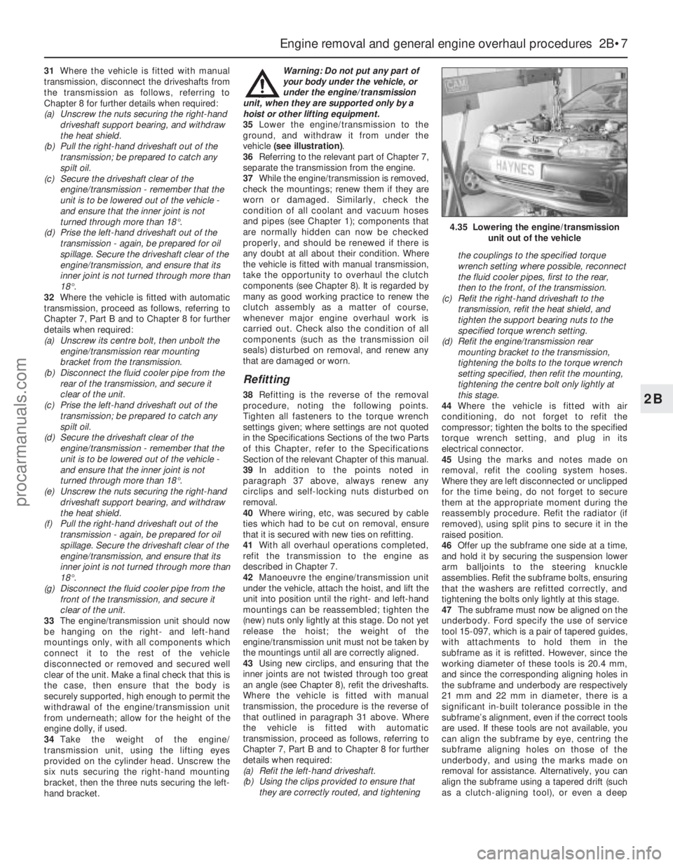
vehicle (see illustration).
36Referring to the relevant part of Chapter 7,
separate the transmission from the engine.
37While the engine/transmission is removed,
check the mountings; renew them if they are
worn or damaged. Similarly, check the
condition of all coolant and vacuum hoses
and pipes (see Chapter 1); components that
are normally hidden can now be checked
properly, and should be renewed if there is
any doubt at all about their condition. Where
the vehicle is fitted with manual transmission,
take the opportunity to overhaul the clutch
components (see Chapter 8). It is regarded by
many as good working practice to renew the
clutch assembly as a matter of course,
whenever major engine overhaul work is
carried out. Check also the condition of all
components (such as the transmission oil
seals) disturbed on removal, and renew any
that are damaged or worn.
Refitting
38Refitting is the reverse of the removal
procedure, noting the following points.
Tighten all fasteners to the torque wrench
settings given; where settings are not quoted
in the Specifications Sections of the two Parts
of this Chapter, refer to the Specifications
Section of the relevant Chapter of this manual.
39In addition to the points noted in
paragraph 37 above, always renew any
circlips and self-locking nuts disturbed on
removal.
40Where wiring, etc, was secured by cable
ties which had to be cut on removal, ensure
that it is secured with new ties on refitting.
41With all overhaul operations completed,
refit the transmission to the engine as
described in Chapter 7.
42Manoeuvre the engine/transmission unit
under the vehicle, attach the hoist, and lift the
unit into position until the right- and left-hand
mountings can be reassembled; tighten the
(new) nuts only lightly at this stage. Do not yet
release the hoist; the weight of the
engine/transmission unit must not be taken by
the mountings until all are correctly aligned.
43Using new circlips, and ensuring that the
inner joints are not twisted through too great
an angle (see Chapter 8), refit the driveshafts.
Where the vehicle is fitted with manual
transmission, the procedure is the reverse of
that outlined in paragraph 31 above. Where
the vehicle is fitted with automatic
transmission, proceed as follows, referring to
Chapter 7, Part B and to Chapter 8 for further
details when required:
(a) Refit the left-hand driveshaft.
(b) Using the clips provided to ensure that
they are correctly routed, and tighteningthe couplings to the specified torque
wrench setting where possible, reconnect
the fluid cooler pipes, first to the rear,
then to the front, of the transmission.
(c) Refit the right-hand driveshaft to the
transmission, refit the heat shield, and
tighten the support bearing nuts to the
specified torque wrench setting.
(d) Refit the engine/transmission rear
mounting bracket to the transmission,
tightening the bolts to the torque wrench
setting specified, then refit the mounting,
tightening the centre bolt only lightly at
this stage.
44Where the vehicle is fitted with air
conditioning, do not forget to refit the
compressor; tighten the bolts to the specified
torque wrench setting, and plug in its
electrical connector.
45Using the marks and notes made on
removal, refit the cooling system hoses.
Where they are left disconnected or unclipped
for the time being, do not forget to secure
them at the appropriate moment during the
reassembly procedure. Refit the radiator (if
removed), using split pins to secure it in the
raised position.
46Offer up the subframe one side at a time,
and hold it by securing the suspension lower
arm balljoints to the steering knuckle
assemblies. Refit the subframe bolts, ensuring
that the washers are refitted correctly, and
tightening the bolts only lightly at this stage.
47The subframe must now be aligned on the
underbody. Ford specify the use of service
tool 15-097, which is a pair of tapered guides,
with attachments to hold them in the
subframe as it is refitted. However, since the
working diameter of these tools is 20.4 mm,
and since the corresponding aligning holes in
the subframe and underbody are respectively
21 mm and 22 mm in diameter, there is a
significant in-built tolerance possible in the
subframe’s alignment, even if the correct tools
are used. If these tools are not available, you
can align the subframe by eye, centring the
subframe aligning holes on those of the
underbody, and using the marks made on
removal for assistance. Alternatively, you can
align the subframe using a tapered drift (such
as a clutch-aligning tool), or even a deep
Engine removal and general engine overhaul procedures 2B•7
2B
4.35 Lowering the engine/transmission
unit out of the vehicle
procarmanuals.com
Page 80 of 279
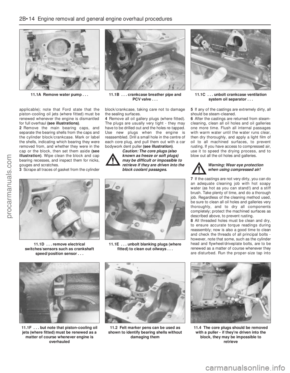
applicable); note that Ford state that the
piston-cooling oil jets (where fitted) must be
renewed whenever the engine is dismantled
for full overhaul (see illustrations).
2Remove the main bearing caps, and
separate the bearing shells from the caps and
the cylinder block/crankcase. Mark or label
the shells, indicating which bearing they were
removed from, and whether they were in the
cap or the block, then set them aside (see
illustration). Wipe clean the block and cap
bearing recesses, and inspect them for nicks,
gouges and scratches.
3Scrape all traces of gasket from the cylinderblock/crankcase, taking care not to damage
the sealing surfaces.
4Remove all oil gallery plugs (where fitted).
The plugs are usually very tight - they may
have to be drilled out and the holes re-tapped.
Use new plugs when the engine is
reassembled. Drill a small hole in the centre of
each core plug, and pull them out with a car
bodywork dent puller (see illustration).
Caution: The core plugs (also
known as freeze or soft plugs)
may be difficult or impossible to
retrieve if they are driven into the
block coolant passages.5If any of the castings are extremely dirty, all
should be steam-cleaned.
6After the castings are returned from steam-
cleaning, clean all oil holes and oil galleries
one more time. Flush all internal passages
with warm water until the water runs clear,
then dry thoroughly, and apply a light film of
oil to all machined surfaces, to prevent
rusting. If you have access to compressed air,
use it to speed the drying process, and to
blow out all the oil holes and galleries.
Warning: Wear eye protection
when using compressed air!
7If the castings are not very dirty, you can do
an adequate cleaning job with hot soapy
water (as hot as you can stand!) and a stiff
brush. Take plenty of time, and do a thorough
job. Regardless of the cleaning method used,
be sure to clean all oil holes and galleries very
thoroughly, and to dry all components
completely; protect the machined surfaces as
described above, to prevent rusting.
8All threaded holes must be clean and dry,
to ensure accurate torque readings during
reassembly; now is also a good time to clean
and check the threads of all principal bolts -
however, note that some, such as the cylinder
head and flywheel/driveplate bolts, are to be
renewed as a matter of course whenever they
are disturbed. Run the proper-size tap into
2B•14 Engine removal and general engine overhaul procedures
11.1A Remove water pump . . .11.1B . . . crankcase breather pipe and
PCV valve . . .11.1C . . . unbolt crankcase ventilation
system oil separator . . .
11.1F . . . but note that piston-cooling oil
jets (where fitted) must be renewed as a
matter of course whenever engine is
overhauled11.2 Felt marker pens can be used as
shown to identify bearing shells without
damaging them
11.1D . . . remove electrical
switches/sensors such as crankshaft
speed/position sensor . . .11.1E . . . unbolt blanking plugs (where
fitted) to clean out oilways . . .
11.4 The core plugs should be removed
with a puller - if they’re driven into the
block, they may be impossible to
retrieve
procarmanuals.com
Page 81 of 279
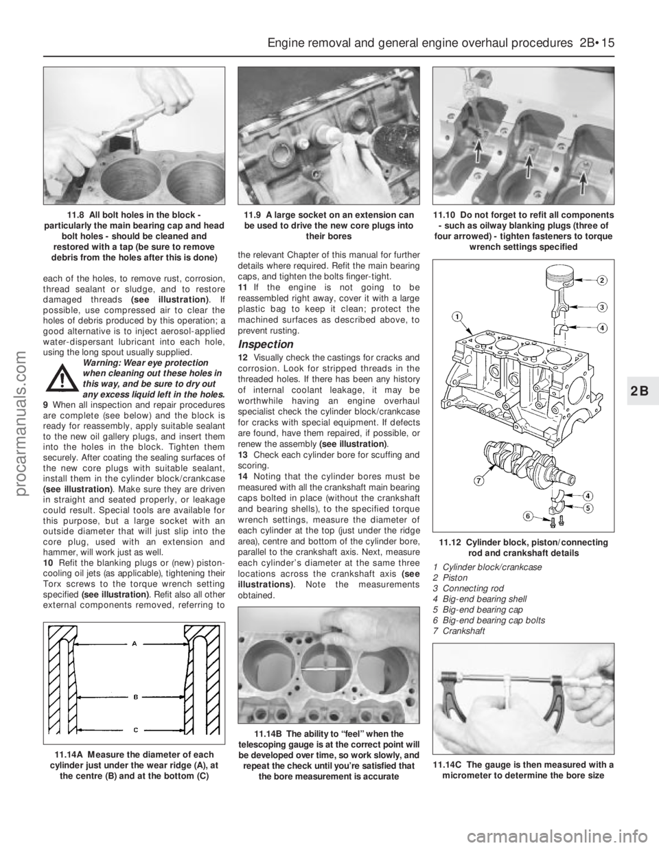
each of the holes, to remove rust, corrosion,
thread sealant or sludge, and to restore
damaged threads (see illustration). If
possible, use compressed air to clear the
holes of debris produced by this operation; a
good alternative is to inject aerosol-applied
water-dispersant lubricant into each hole,
using the long spout usually supplied.
Warning: Wear eye protection
when cleaning out these holes in
this way, and be sure to dry out
any excess liquid left in the holes.
9When all inspection and repair procedures
are complete (see below) and the block is
ready for reassembly, apply suitable sealant
to the new oil gallery plugs, and insert them
into the holes in the block. Tighten them
securely. After coating the sealing surfaces of
the new core plugs with suitable sealant,
install them in the cylinder block/crankcase
(see illustration). Make sure they are driven
in straight and seated properly, or leakage
could result. Special tools are available for
this purpose, but a large socket with an
outside diameter that will just slip into the
core plug, used with an extension and
hammer, will work just as well.
10Refit the blanking plugs or (new) piston-
cooling oil jets (as applicable), tightening their
Torx screws to the torque wrench setting
specified (see illustration). Refit also all other
external components removed, referring tothe relevant Chapter of this manual for further
details where required. Refit the main bearing
caps, and tighten the bolts finger-tight.
11If the engine is not going to be
reassembled right away, cover it with a large
plastic bag to keep it clean; protect the
machined surfaces as described above, to
prevent rusting.
Inspection
12Visually check the castings for cracks and
corrosion. Look for stripped threads in the
threaded holes. If there has been any history
of internal coolant leakage, it may be
worthwhile having an engine overhaul
specialist check the cylinder block/crankcase
for cracks with special equipment. If defects
are found, have them repaired, if possible, or
renew the assembly (see illustration).
13Check each cylinder bore for scuffing and
scoring.
14Noting that the cylinder bores must be
measured with all the crankshaft main bearing
caps bolted in place (without the crankshaft
and bearing shells), to the specified torque
wrench settings, measure the diameter of
each cylinder at the top (just under the ridge
area), centre and bottom of the cylinder bore,
parallel to the crankshaft axis. Next, measure
each cylinder’s diameter at the same three
locations across the crankshaft axis (see
illustrations). Note the measurements
obtained.
Engine removal and general engine overhaul procedures 2B•15
2B
11.12 Cylinder block, piston/connecting
rod and crankshaft details
1 Cylinder block/crankcase
2 Piston
3 Connecting rod
4 Big-end bearing shell
5 Big-end bearing cap
6 Big-end bearing cap bolts
7 Crankshaft
11.14A Measure the diameter of each
cylinder just under the wear ridge (A), at
the centre (B) and at the bottom (C)
11.14B The ability to “feel” when the
telescoping gauge is at the correct point will
be developed over time, so work slowly, and
repeat the check until you’re satisfied that
the bore measurement is accurate
11.8 All bolt holes in the block -
particularly the main bearing cap and head
bolt holes - should be cleaned and
restored with a tap (be sure to remove
debris from the holes after this is done)11.9 A large socket on an extension can
be used to drive the new core plugs into
their bores11.10 Do not forget to refit all components
- such as oilway blanking plugs (three of
four arrowed) - tighten fasteners to torque
wrench settings specified
11.14C The gauge is then measured with a
micrometer to determine the bore size
procarmanuals.com
Page 84 of 279
Note:Always check first what replacement
parts are available before planning any
overhaul operation; refer to Section 1 of this
Part. A Ford dealer, or a good engine
reconditioning specialist/automotive parts
supplier, may be able to suggest alternatives
which will enable you to overcome the lack of
replacement parts.
1Clean the crankshaft, and dry it with
compressed air if available.
Warning: Wear eye protection
when using compressed air! Be
sure to clean the oil holes with a
pipe cleaner or similar probe.
2Check the main and crankpin (big-end)
bearing journals for uneven wear, scoring,
pitting and cracking.
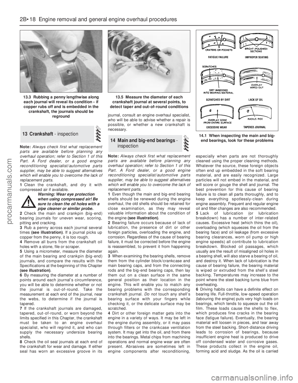
3Rub a penny across each journal several
times (see illustration). If a journal picks up
copper from the penny, it is too rough.
4Remove all burrs from the crankshaft oil
holes with a stone, file or scraper.
5Using a micrometer, measure the diameter
of the main bearing and crankpin (big-end)
journals, and compare the results with the
Specifications at the beginning of this Chapter
(see illustration).
6By measuring the diameter at a number of
points around each journal’s circumference,
you will be able to determine whether or not
the journal is out-of-round. Take the
measurement at each end of the journal, near
the webs, to determine if the journal is
tapered.
7If the crankshaft journals are damaged,
tapered, out-of-round, or worn beyond the
limits specified in this Chapter, the crankshaft
must be taken to an engine overhaul
specialist, who will regrind it, and who can
supply the necessary undersize bearing
shells.
8Check the oil seal journals at each end of
the crankshaft for wear and damage. If either
seal has worn an excessive groove in itsjournal, consult an engine overhaul specialist,
who will be able to advise whether a repair is
possible, or whether a new crankshaft is
necessary.
Note:Always check first what replacement
parts are available before planning any
overhaul operation; refer to Section 1 of this
Part. A Ford dealer, or a good engine
reconditioning specialist/automotive parts
supplier, may be able to suggest alternatives
which will enable you to overcome the lack of
replacement parts.
1Even though the main and big-end bearing
shells should be renewed during the engine
overhaul, the old shells should be retained for
close examination, as they may reveal
valuable information about the condition of
the engine (see illustration).
2Bearing failure occurs because of lack of
lubrication, the presence of dirt or other
foreign particles, overloading the engine, and
corrosion. Regardless of the cause of bearing
failure, it must be corrected before the engine
is reassembled, to prevent it from happening
again.
3When examining the bearing shells, remove
them from the cylinder block/crankcase and
main bearing caps, and from the connecting
rods and the big-end bearing caps, then lay
them out on a clean surface in the same
general position as their location in the
engine. This will enable you to match any
bearing problems with the corresponding
crankshaft journal. Do nottouch any shell’s
bearing surface with your fingers while
checking it, or the delicate surface may be
scratched.
4Dirt or other foreign matter gets into the
engine in a variety of ways. It may be left in
the engine during assembly, or it may pass
through filters or the crankcase ventilation
system. It may get into the oil, and from there
into the bearings. Metal chips from machining
operations and normal engine wear are often
present. Abrasives are sometimes left in
engine components after reconditioning,especially when parts are not thoroughly
cleaned using the proper cleaning methods.
Whatever the source, these foreign objects
often end up embedded in the soft bearing
material, and are easily recognized. Large
particles will not embed in the material, and
will score or gouge the shell and journal. The
best prevention for this cause of bearing
failure is to clean all parts thoroughly, and to
keep everything spotlessly-clean during
engine assembly. Frequent and regular engine
oil and filter changes are also recommended.
5Lack of lubrication (or lubrication
breakdown) has a number of inter-related
causes. Excessive heat (which thins the oil),
overloading (which squeezes the oil from the
bearing face) and oil leakage (from excessive
bearing clearances, worn oil pump or high
engine speeds) all contribute to lubrication
breakdown. Blocked oil passages, which
usually are the result of misaligned oil holes in
a bearing shell, will also starve a bearing of oil,
and destroy it. When lack of lubrication is the
cause of bearing failure, the bearing material
is wiped or extruded from the shell’s steel
backing. Temperatures may increase to the
point where the steel backing turns blue from
overheating.
6Driving habits can have a definite effect on
bearing life. Full-throttle, low-speed operation
(labouring the engine) puts very high loads on
bearings, which tends to squeeze out the oil
film. These loads cause the shells to flex,
which produces fine cracks in the bearing
face (fatigue failure). Eventually, the bearing
material will loosen in pieces, and tear away
from the steel backing. Short-distance driving
leads to corrosion of bearings, because
insufficient engine heat is produced to drive
off condensed water and corrosive gases.
These products collect in the engine oil,
forming acid and sludge. As the oil is carried
14 Main and big-end bearings-
inspection
13 Crankshaft - inspection
2B•18 Engine removal and general engine overhaul procedures
13.3 Rubbing a penny lengthwise along
each journal will reveal its condition - if
copper rubs off and is embedded in the
crankshaft, the journals should be
reground13.5 Measure the diameter of each
crankshaft journal at several points, to
detect taper and out-of-round conditions
14.1 When inspecting the main and big-
end bearings, look for these problems
procarmanuals.com
Page 88 of 279
rod’s big-end onto the crankpin. The piston
rings may try to pop out of the ring
compressor just before entering the cylinder
bore, so keep some pressure on the ring
compressor. Work slowly, and if any
resistance is felt as the piston enters the
cylinder, stop immediately. Find out what’s
binding, and fix it before proceeding. Do not,
for any reason, force the piston into the
cylinder - you might break a ring and/or the
piston.
10To check the big-end bearing running
clearance, cut a piece of the appropriate-size
Plastigage slightly shorter than the width of
the connecting rod bearing, and lay it in place
on the No 1 crankpin (big-end) journal, parallel
with the crankshaft centre-line (see illus-
tration 17.6).
11Clean the connecting rod-to-cap mating
surfaces, and refit the big-end bearing cap.
Make sure the etched number on the cap is
on the same side as that on the rod (see
illustration). Tighten the cap bolts evenly -
first use a torque wrench to tighten the bolts
to the specified (first stage) torque setting,
then use an ordinary socket extension bar
and an angle gauge to tighten the bolts
further through the specified (second stage)
angle. Use a thin-wall socket, to avoid
erroneous torque readings that can result if
the socket is wedged between the cap and
nut. If the socket tends to wedge itself
between the nut and the cap, lift up on it
slightly until it no longer contacts the cap.
Don’t rotate the crankshaft at any time during
this operation!
12Unscrew the bolts and detach the cap,
being very careful not to disturb the
Plastigage.
13Compare the width of the crushed
Plastigage to the scale printed on the
Plastigage envelope, to obtain the running
clearance (see illustration 17.10). Compare it
to the Specifications, to make sure the
clearance is correct.
14If the clearance is not as specified, seek
the advice of a Ford dealer or similar engine
reconditioning specialist - if the crankshaft
journals are in good condition (see Sec-
tion 13), it may be possible simply to renew
the shells to achieve the correct clearance. If
this is not possible, the crankshaft must bereground by a specialist, who can also supply
the necessary undersized shells. First though,
make sure that no dirt or oil was trapped
between the bearing shells and the
connecting rod or cap when the clearance
was measured. Also, recheck the crankpin
diameter. If the Plastigage was wider at one
end than the other, the crankpin journal may
be tapered (see Section 13).
15Carefully scrape all traces of the
Plastigage material off the journal and the
bearing surface. Be very careful not to scratch
the bearing - use your fingernail or the edge of
a credit card.
Final piston/connecting rod
refitting
16Make sure the bearing surfaces are
perfectly clean, then apply a uniform layer of
clean molybdenum disulphide-based grease,
engine assembly lubricant, or clean engine oil,
to both of them. You’ll have to push the piston
into the cylinder to expose the bearing surface
of the shell in the connecting rod.
17Slide the connecting rod back into place
on the crankpin (big-end) journal, refit the big-
end bearing cap, and then tighten the bolts in
two stages, as described above.
18Repeat the entire procedure for the
remaining piston/connecting rod assemblies.
19The important points to remember are:
(a) Keep the backs of the bearing shells and
the recesses of the connecting rods and
caps perfectly clean when assembling
them.
(b) Make sure you have the correct
piston/rod assembly for each cylinder -
use the etched cylinder numbers to
identify the front-facing side of both the
rod and its cap.
(c) The arrow on the piston crown must face
the timing belt end of the engine.
(d) Lubricate the cylinder bores with clean
engine oil.
(e) Lubricate the bearing surfaces when
refitting the big-end bearing caps after the
running clearance has been checked.
20After all the piston/connecting rod
assemblies have been properly installed,
rotate the crankshaft a number of times by
hand, to check for any obvious binding.1With the engine refitted in the vehicle,
double-check the engine oil and coolant
levels. Make a final check that everything has
been reconnected, and that there are no tools
or rags left in the engine compartment.
2With the spark plugs removed and the
ignition system disabled by unplugging the
ignition coil’s electrical connector, remove
fuse 14 to disconnect the fuel pump. Turn the
engine on the starter until the oil pressure
warning light goes out.
3Refit the spark plugs, and connect all the
spark plug (HT) leads (Chapter 1). Reconnect
the ignition coil wiring, refit the fuel pump fuse,
then switch on the ignition and listen for the fuel
pump; it will run for a little longer than usual,
due to the lack of pressure in the system.
4Start the engine, noting that this also may
take a little longer than usual, due to the fuel
system components being empty.
5While the engine is idling, check for fuel,
coolant and oil leaks. Don’t be alarmed if
there are some odd smells and smoke from
parts getting hot and burning off oil deposits.
If the hydraulic tappets have been disturbed,
some valve gear noise may be heard at first;
this should disappear as the oil circulates fully
around the engine, and normal pressure is
restored in the tappets.
6Keep the engine idling until hot water is felt
circulating through the top hose, check that it
idles reasonably smoothly and at the usual
speed, then switch it off.
7After a few minutes, recheck the oil and
coolant levels, and top-up as necessary
(Chapter 1).
8If they were tightened as described, there is
no need to re-tighten the cylinder head bolts
once the engine has first run after reassembly
- in fact, Ford state that the bolts must notbe
re-tightened.
9If new components such as pistons, rings
or crankshaft bearings have been fitted, the
engine must be run-in for the first 500 miles
(800 km). Do not operate the engine at full-
throttle, or allow it to labour in any gear during
this period. It is recommended that the oil and
filter be changed at the end of this period.
19 Engine -
initial start-up after overhaul
2B•22 Engine removal and general engine overhaul procedures
procarmanuals.com
Page 90 of 279
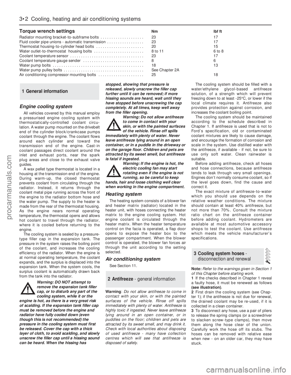
Torque wrench settingsNm lbf ft
Radiator mounting bracket-to-subframe bolts . . . . . . . . . . . . . . . . . . . . 23 17
Fluid cooler pipe unions - automatic transmission . . . . . . . . . . . . . . . . . 23 17
Thermostat housing-to-cylinder head bolts . . . . . . . . . . . . . . . . . . . . . . 20 15
Water outlet-to-thermostat housing bolts . . . . . . . . . . . . . . . . . . . . . . . 8 to 11 6 to 8
Coolant temperature sensor . . . . . . . . . . . . . . . . . . . . . . . . . . . . . . . . . . 23 17
Coolant temperature gauge sender . . . . . . . . . . . . . . . . . . . . . . . . . . . . 8 6
Water pump bolts . . . . . . . . . . . . . . . . . . . . . . . . . . . . . . . . . . . . . . . . . . 18 13
Water pump pulley bolts . . . . . . . . . . . . . . . . . . . . . . . . . . . . . . . . . . . . . See Chapter 2A
Air conditioning compressor mounting bolts . . . . . . . . . . . . . . . . . . . . . 25 18
3•2 Cooling, heating and air conditioning systems
Engine cooling system
All vehicles covered by this manual employ
a pressurised engine cooling system with
thermostatically-controlled coolant circu-
lation. A water pump mounted on the drivebelt
end of the cylinder block/crankcase pumps
coolant through the engine. The coolant flows
around each cylinder and toward the
transmission end of the engine. Cast-in
coolant passages direct coolant around the
inlet and exhaust ports, near the spark
plug areas and close to the exhaust valve
guides.
A wax pellet type thermostat is located in a
housing at the transmission end of the engine.
During warm-up, the closed thermostat
prevents coolant from circulating through the
radiator. Instead, it returns through the
coolant metal pipe running across the front of
the engine to the radiator bottom hose and
the water pump. The supply to the heater is
made from the rear of the thermostat housing.
As the engine nears normal operating
temperature, the thermostat opens and allows
hot coolant to travel through the radiator,
where it is cooled before returning to the
engine.
The cooling system is sealed by a pressure-
type filler cap in the expansion tank. The
pressure in the system raises the boiling point
of the coolant, and increases the cooling
efficiency of the radiator. When the engine is
at normal operating temperature, the coolant
expands, and the surplus is displaced into the
expansion tank. When the system cools, the
surplus coolant is automatically drawn back
from the tank into the radiator.
Warning: DO NOT attempt to
remove the expansion tank filler
cap, or to disturb any part of the
cooling system, while it or the
engine is hot, as there is a very great risk
of scalding. If the expansion tank filler cap
must be removed before the engine and
radiator have fully cooled down (even
though this is not recommended) the
pressure in the cooling system must first
be released. Cover the cap with a thick
layer of cloth, to avoid scalding, and slowly
unscrew the filler cap until a hissing sound
can be heard. When the hissing hasstopped, showing that pressure is
released, slowly unscrew the filler cap
further until it can be removed; if more
hissing sounds are heard, wait until they
have stopped before unscrewing the cap
completely. At all times, keep well away
from the filler opening.
Warning: Do not allow antifreeze
to come in contact with your
skin, or with the painted surfaces
of the vehicle. Rinse off spills
immediately with plenty of water. Never
leave antifreeze lying around in an open
container, or in a puddle in the driveway or
on the garage floor. Children and pets are
attracted by its sweet smell, but antifreeze
is fatal if ingested.
Warning: If the engine is hot, the
electric cooling fan may start
rotating even if the engine is not
running, so be careful to keep
hands, hair and loose clothing well clear
when working in the engine compartment.
Heating system
The heating system consists of a blower fan
and heater matrix (radiator) located in the
heater unit, with hoses connecting the heater
matrix to the engine cooling system. Hot
engine coolant is circulated through the
heater matrix. When the heater temperature
control on the facia is operated, a flap door
opens to expose the heater box to the
passenger compartment. When the blower
control is operated, the blower fan forces air
through the unit according to the setting
selected.
Air conditioning system
See Section 11.
Warning: Do not allow antifreeze to come in
contact with your skin, or with the painted
surfaces of the vehicle. Rinse off spills
immediately with plenty of water. Antifreeze is
highly toxic if ingested. Never leave antifreeze
lying around in an open container, or in
puddles on the floor; children and pets are
attracted by its sweet smell, and may drink it.
Check with local authorities about disposing
of used antifreeze - many have collection
centres which will see that antifreeze is
disposed of safely.The cooling system should be filled with a
water/ethylene glycol-based antifreeze
solution, of a strength which will prevent
freezing down to at least -25°C, or lower if the
local climate requires it. Antifreeze also
provides protection against corrosion, and
increases the coolant boiling point.
The cooling system should be maintained
according to the schedule described in
Chapter 1. If antifreeze is used that is not to
Ford’s specification, old or contaminated
coolant mixtures are likely to cause damage,
and encourage the formation of corrosion and
scale in the system. Use distilled water with
the antifreeze, if available - if not, be sure to
use only soft water. Clean rainwater is
suitable.
Before adding antifreeze, check all hoses
and hose connections, because antifreeze
tends to leak through very small openings.
Engines don’t normally consume coolant, so if
the level goes down, find the cause and
correct it.
The exact mixture of antifreeze-to-water
which you should use depends on the
relative weather conditions. The mixture
should contain at least 40% antifreeze, but
not more than 70%. Consult the mixture
ratio chart on the antifreeze container
before adding coolant. Hydrometers are
available at most automotive accessory
shops to test the coolant. Use antifreeze
which meets the vehicle manufacturer’s
specifications.
Note:Refer to the warnings given in Section 1
of this Chapter before starting work.
1If the checks described in Chapter 1 reveal
a faulty hose, it must be renewed as follows
(see illustration).
2First drain the cooling system (see Chap-
ter 1); if the antifreeze is not due for renewal,
the drained coolant may be re-used, if it is
collected in a clean container.
3To disconnect any hose, use a pair of pliers
to release the spring clamps (or a screwdriver
to slacken screw-type clamps), then move
them along the hose clear of the union.
Carefully work the hose off its stubs. The
hoses can be removed with relative ease
when new - on an older car, they may have
stuck.
3 Cooling system hoses -
disconnection and renewal
2 Antifreeze - general information
1 General information
procarmanuals.com