transmission FORD MONDEO 1993 Service Manual PDF
[x] Cancel search | Manufacturer: FORD, Model Year: 1993, Model line: MONDEO, Model: FORD MONDEO 1993Pages: 279, PDF Size: 12.71 MB
Page 208 of 279
Main light, auxiliary foglight and rear
foglight combination switch
Note:From July 1994 a rvised main light
switch was introduced; this was fitted as
standard in production. If the revised switch is
to be fitted to a pre-July 1994 model, an
adapter lead will also be required to prevent
electrical damage ocurring. Refer to your Ford
dealer for further information
9Disconnect the battery negative (earth) lead
(refer to Chapter 5, Section 1).
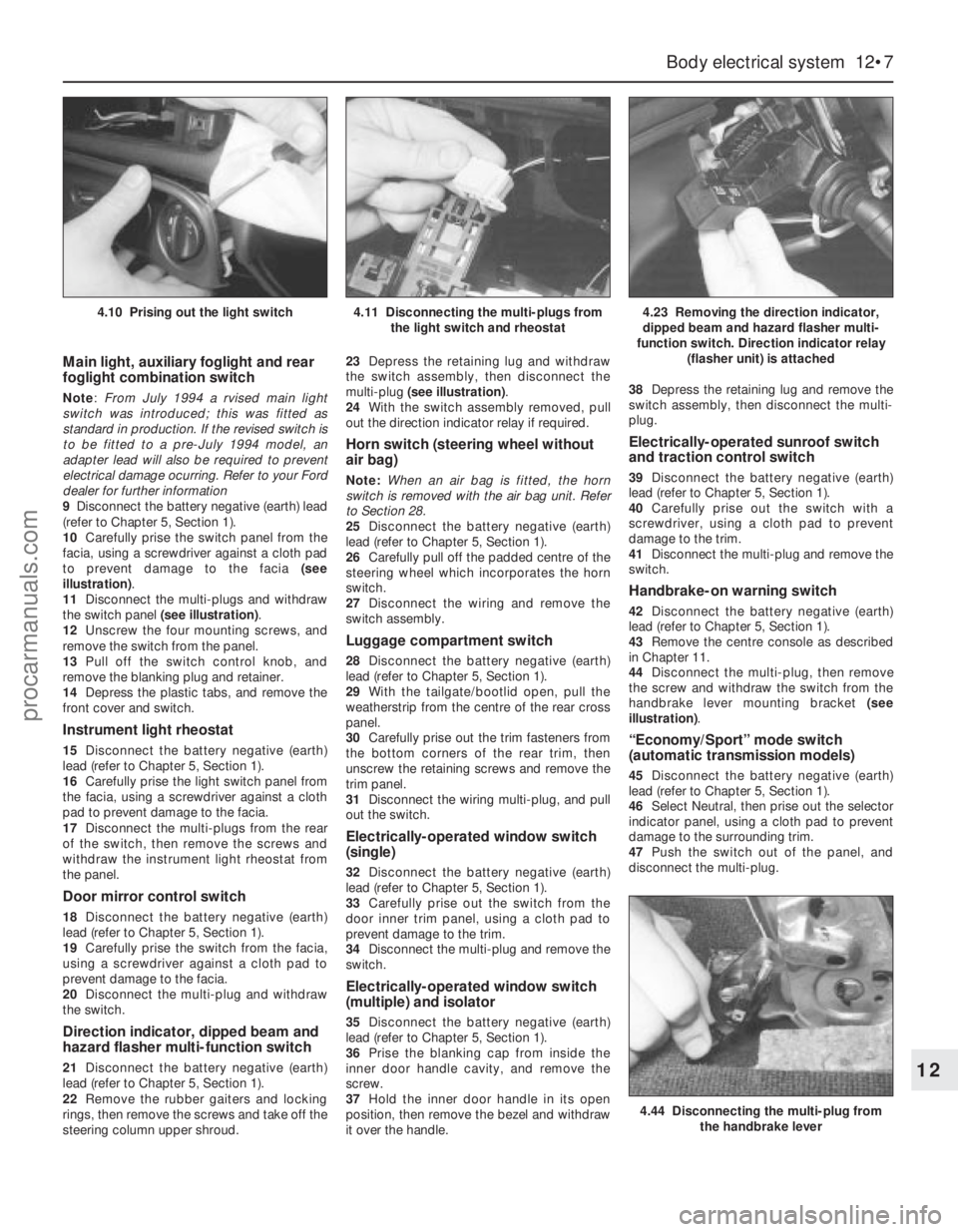
10Carefully prise the switch panel from the
facia, using a screwdriver against a cloth pad
to prevent damage to the facia (see
illustration).
11Disconnect the multi-plugs and withdraw
the switch panel (see illustration).
12Unscrew the four mounting screws, and
remove the switch from the panel.
13Pull off the switch control knob, and
remove the blanking plug and retainer.
14Depress the plastic tabs, and remove the
front cover and switch.
Instrument light rheostat
15Disconnect the battery negative (earth)
lead (refer to Chapter 5, Section 1).
16Carefully prise the light switch panel from
the facia, using a screwdriver against a cloth
pad to prevent damage to the facia.
17Disconnect the multi-plugs from the rear
of the switch, then remove the screws and
withdraw the instrument light rheostat from
the panel.
Door mirror control switch
18Disconnect the battery negative (earth)
lead (refer to Chapter 5, Section 1).
19Carefully prise the switch from the facia,
using a screwdriver against a cloth pad to
prevent damage to the facia.
20Disconnect the multi-plug and withdraw
the switch.
Direction indicator, dipped beam and
hazard flasher multi-function switch
21Disconnect the battery negative (earth)
lead (refer to Chapter 5, Section 1).
22Remove the rubber gaiters and locking
rings, then remove the screws and take off the
steering column upper shroud.23Depress the retaining lug and withdraw
the switch assembly, then disconnect the
multi-plug (see illustration).
24With the switch assembly removed, pull
out the direction indicator relay if required.
Horn switch (steering wheel without
air bag)
Note:When an air bag is fitted, the horn
switch is removed with the air bag unit. Refer
to Section 28.
25Disconnect the battery negative (earth)
lead (refer to Chapter 5, Section 1).
26Carefully pull off the padded centre of the
steering wheel which incorporates the horn
switch.
27Disconnect the wiring and remove the
switch assembly.
Luggage compartment switch
28Disconnect the battery negative (earth)
lead (refer to Chapter 5, Section 1).
29With the tailgate/bootlid open, pull the
weatherstrip from the centre of the rear cross
panel.
30Carefully prise out the trim fasteners from
the bottom corners of the rear trim, then
unscrew the retaining screws and remove the
trim panel.
31Disconnect the wiring multi-plug, and pull
out the switch.
Electrically-operated window switch
(single)
32Disconnect the battery negative (earth)
lead (refer to Chapter 5, Section 1).
33Carefully prise out the switch from the
door inner trim panel, using a cloth pad to
prevent damage to the trim.
34Disconnect the multi-plug and remove the
switch.
Electrically-operated window switch
(multiple) and isolator
35Disconnect the battery negative (earth)
lead (refer to Chapter 5, Section 1).
36Prise the blanking cap from inside the
inner door handle cavity, and remove the
screw.
37Hold the inner door handle in its open
position, then remove the bezel and withdraw
it over the handle.38Depress the retaining lug and remove the
switch assembly, then disconnect the multi-
plug.
Electrically-operated sunroof switch
and traction control switch
39Disconnect the battery negative (earth)
lead (refer to Chapter 5, Section 1).
40Carefully prise out the switch with a
screwdriver, using a cloth pad to prevent
damage to the trim.
41Disconnect the multi-plug and remove the
switch.
Handbrake-on warning switch
42Disconnect the battery negative (earth)
lead (refer to Chapter 5, Section 1).
43Remove the centre console as described
in Chapter 11.
44Disconnect the multi-plug, then remove
the screw and withdraw the switch from the
handbrake lever mounting bracket (see
illustration).
“Economy/Sport” mode switch
(automatic transmission models)
45Disconnect the battery negative (earth)
lead (refer to Chapter 5, Section 1).
46Select Neutral, then prise out the selector
indicator panel, using a cloth pad to prevent
damage to the surrounding trim.
47Push the switch out of the panel, and
disconnect the multi-plug.
Body electrical system 12•7
12
4.44 Disconnecting the multi-plug from
the handbrake lever
4.10 Prising out the light switch4.11 Disconnecting the multi-plugs from
the light switch and rheostat4.23 Removing the direction indicator,
dipped beam and hazard flasher multi-
function switch. Direction indicator relay
(flasher unit) is attached
procarmanuals.com
Page 212 of 279
Engine compartment light
1With the bonnet open, pull the wedge-type
bulb from the bulbholder.
2Fit the new bulb using a reversal of the
removal procedure.
Interior lights
3Switch off the interior light by locating the
switch in its middle position.
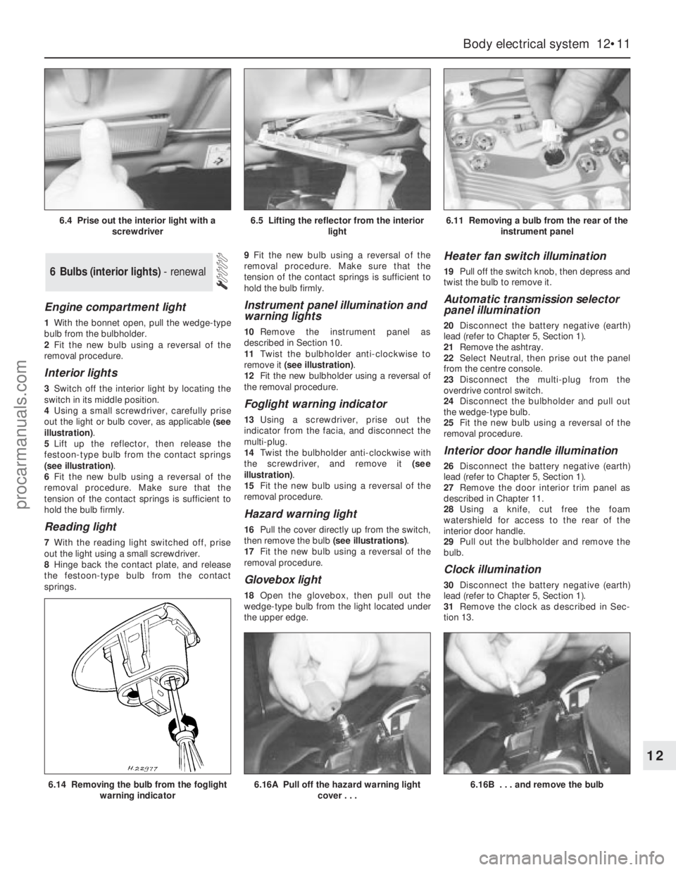
4Using a small screwdriver, carefully prise
out the light or bulb cover, as applicable (see
illustration).
5Lift up the reflector, then release the
festoon-type bulb from the contact springs
(see illustration).
6Fit the new bulb using a reversal of the
removal procedure. Make sure that the
tension of the contact springs is sufficient to
hold the bulb firmly.
Reading light
7With the reading light switched off, prise
out the light using a small screwdriver.
8Hinge back the contact plate, and release
the festoon-type bulb from the contact
springs.9Fit the new bulb using a reversal of the
removal procedure. Make sure that the
tension of the contact springs is sufficient to
hold the bulb firmly.
Instrument panel illumination and
warning lights
10Remove the instrument panel as
described in Section 10.
11Twist the bulbholder anti-clockwise to
remove it (see illustration).
12Fit the new bulbholder using a reversal of
the removal procedure.
Foglight warning indicator
13Using a screwdriver, prise out the
indicator from the facia, and disconnect the
multi-plug.
14Twist the bulbholder anti-clockwise with
the screwdriver, and remove it (see
illustration).
15Fit the new bulb using a reversal of the
removal procedure.
Hazard warning light
16Pull the cover directly up from the switch,
then remove the bulb (see illustrations).
17Fit the new bulb using a reversal of the
removal procedure.
Glovebox light
18Open the glovebox, then pull out the
wedge-type bulb from the light located under
the upper edge.
Heater fan switch illumination
19Pull off the switch knob, then depress and
twist the bulb to remove it.
Automatic transmission selector
panel illumination
20Disconnect the battery negative (earth)
lead (refer to Chapter 5, Section 1).
21Remove the ashtray.
22Select Neutral, then prise out the panel
from the centre console.
23Disconnect the multi-plug from the
overdrive control switch.
24Disconnect the bulbholder and pull out
the wedge-type bulb.
25Fit the new bulb using a reversal of the
removal procedure.
Interior door handle illumination
26Disconnect the battery negative (earth)
lead (refer to Chapter 5, Section 1).
27Remove the door interior trim panel as
described in Chapter 11.
28Using a knife, cut free the foam
watershield for access to the rear of the
interior door handle.
29Pull out the bulbholder and remove the
bulb.
Clock illumination
30Disconnect the battery negative (earth)
lead (refer to Chapter 5, Section 1).
31Remove the clock as described in Sec-
tion 13.
6 Bulbs (interior lights) - renewal
Body electrical system 12•11
12
6.14 Removing the bulb from the foglight
warning indicator6.16A Pull off the hazard warning light
cover . . .6.16B . . . and remove the bulb
6.4 Prise out the interior light with a
screwdriver6.5 Lifting the reflector from the interior
light6.11 Removing a bulb from the rear of the
instrument panel
procarmanuals.com
Page 216 of 279
6Similarly remove the fuel gauge and
temperature gauge by unscrewing the single
screws.
7Remove all the pin contacts.
8Using a small punch, push in the multi-plug
securing pins, and remove the multi-plugs.
9Carefully lift the printed circuit from the
location dowels on the housing, taking care
not to damage it.
Refitting
10Refitting is a reversal of the removal
procedure.
Removal
1Remove the windscreen wiper arms as
described in Section 15.
2With the bonnet closed, release the grille
panel upper edge from just in front of the
windscreen, by prising off the caps and
unscrewing the upper retaining screws.
3Open the bonnet, and support with the
stay.
4Pull off the sealing strip from the cross
panel at the rear of the engine compartment.
5Unscrew the lower screws, and remove the
grille panel halves from in front of thewindscreen, withdrawing first one side and
then the other.
6Disconnect the battery negative (earth) lead
(refer to Chapter 5, Section 1).
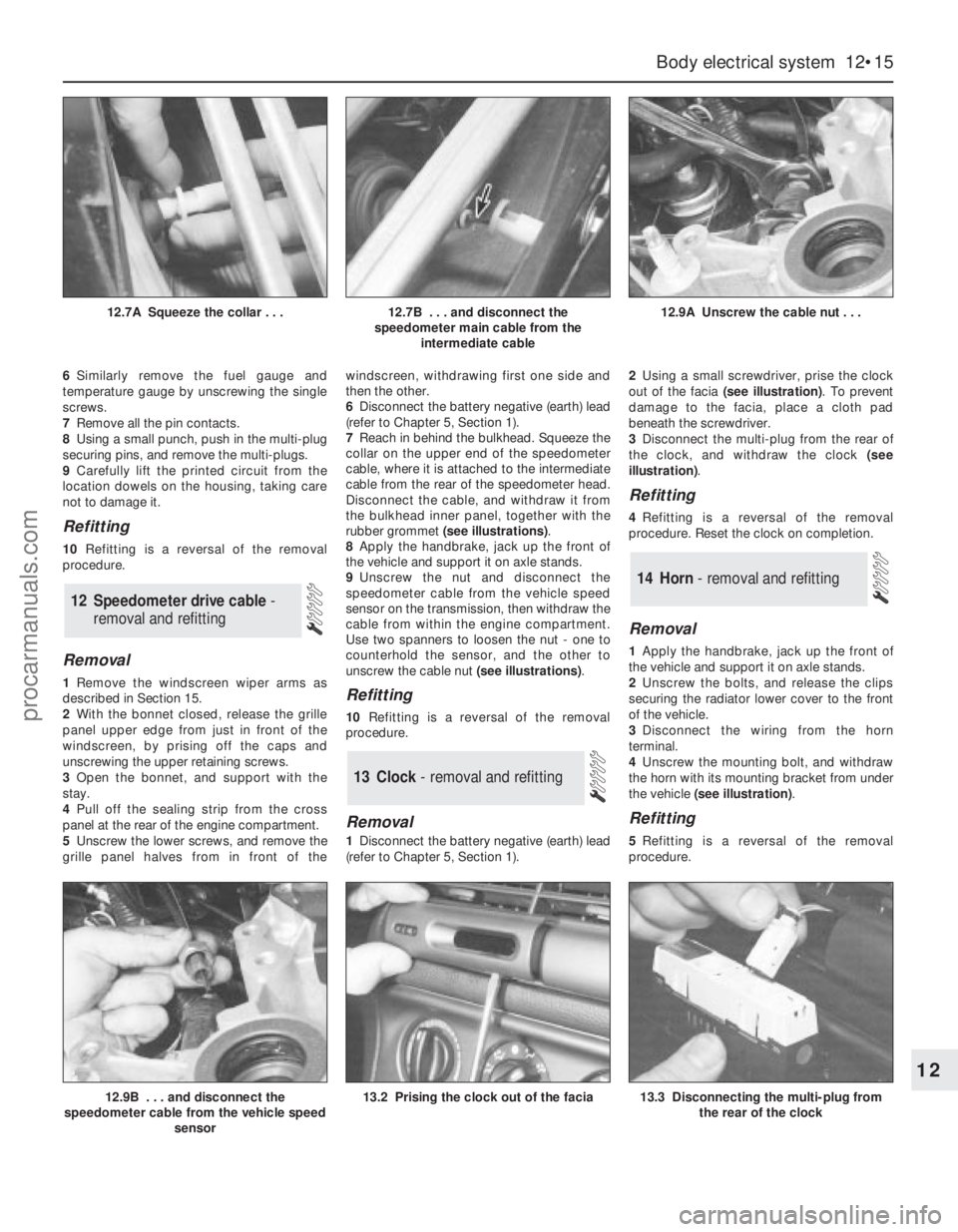
7Reach in behind the bulkhead. Squeeze the
collar on the upper end of the speedometer
cable, where it is attached to the intermediate
cable from the rear of the speedometer head.
Disconnect the cable, and withdraw it from
the bulkhead inner panel, together with the
rubber grommet (see illustrations).
8Apply the handbrake, jack up the front of
the vehicle and support it on axle stands.
9Unscrew the nut and disconnect the
speedometer cable from the vehicle speed
sensor on the transmission, then withdraw the
cable from within the engine compartment.
Use two spanners to loosen the nut - one to
counterhold the sensor, and the other to
unscrew the cable nut (see illustrations).Refitting
10Refitting is a reversal of the removal
procedure.
Removal
1Disconnect the battery negative (earth) lead
(refer to Chapter 5, Section 1).2Using a small screwdriver, prise the clock
out of the facia (see illustration). To prevent
damage to the facia, place a cloth pad
beneath the screwdriver.
3Disconnect the multi-plug from the rear of
the clock, and withdraw the clock (see
illustration).
Refitting
4Refitting is a reversal of the removal
procedure. Reset the clock on completion.
Removal
1Apply the handbrake, jack up the front of
the vehicle and support it on axle stands.
2Unscrew the bolts, and release the clips
securing the radiator lower cover to the front
of the vehicle.
3Disconnect the wiring from the horn
terminal.
4Unscrew the mounting bolt, and withdraw
the horn with its mounting bracket from under
the vehicle (see illustration).
Refitting
5Refitting is a reversal of the removal
procedure.
14 Horn - removal and refitting
13 Clock- removal and refitting
12 Speedometer drive cable -
removal and refitting
Body electrical system 12•15
12
12.9B . . . and disconnect the
speedometer cable from the vehicle speed
sensor13.2 Prising the clock out of the facia13.3 Disconnecting the multi-plug from
the rear of the clock
12.7A Squeeze the collar . . .12.7B . . . and disconnect the
speedometer main cable from the
intermediate cable12.9A Unscrew the cable nut . . .
procarmanuals.com
Page 227 of 279
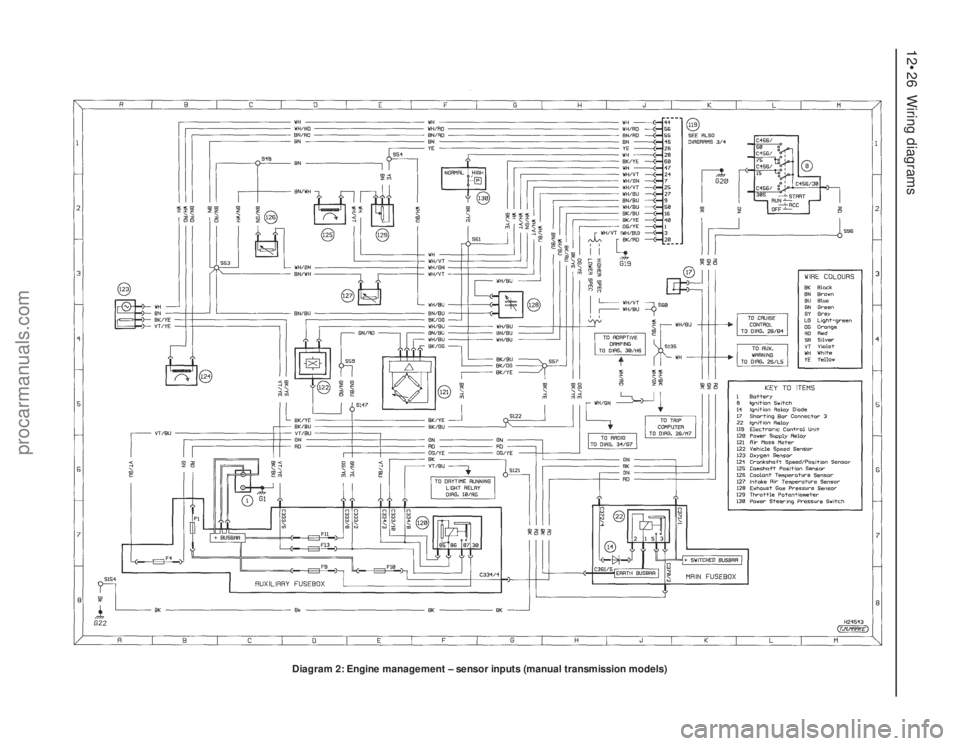
12•26 Wiring diagrams
Diagram 2: Engine management – sensor inputs (manual transmission models)
procarmanuals.com
Page 228 of 279
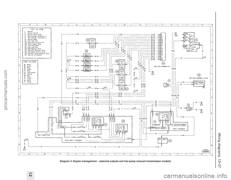
Wiring diagrams 12•27
12
Diagram 3: Engine management – solenoid outputs and fuel pump (manual transmission models)
procarmanuals.com
Page 229 of 279
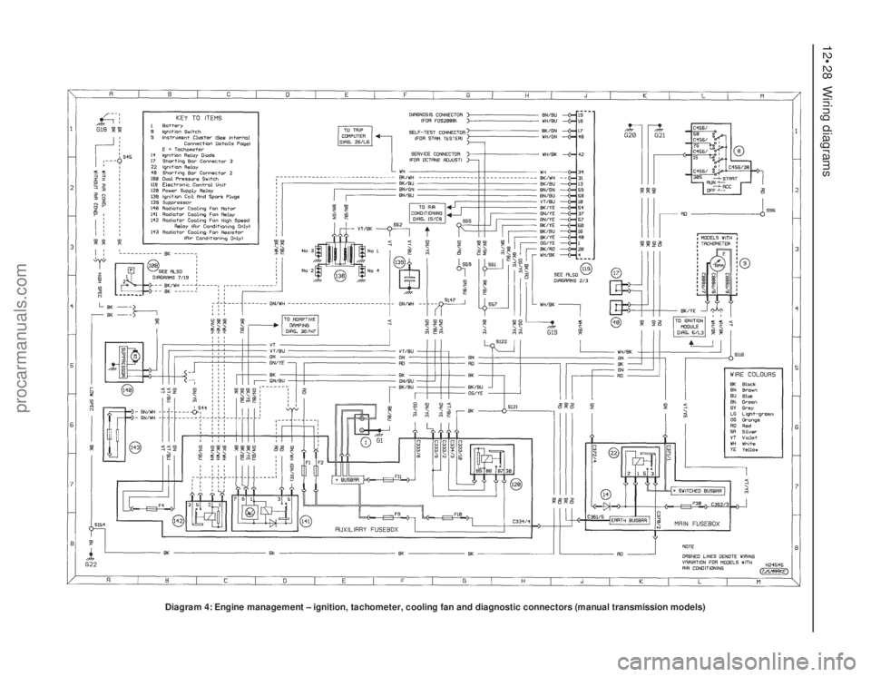
12•28 Wiring diagrams
Diagram 4: Engine management – ignition, tachometer, cooling fan and diagnostic connectors (manual transmission models)
procarmanuals.com
Page 230 of 279
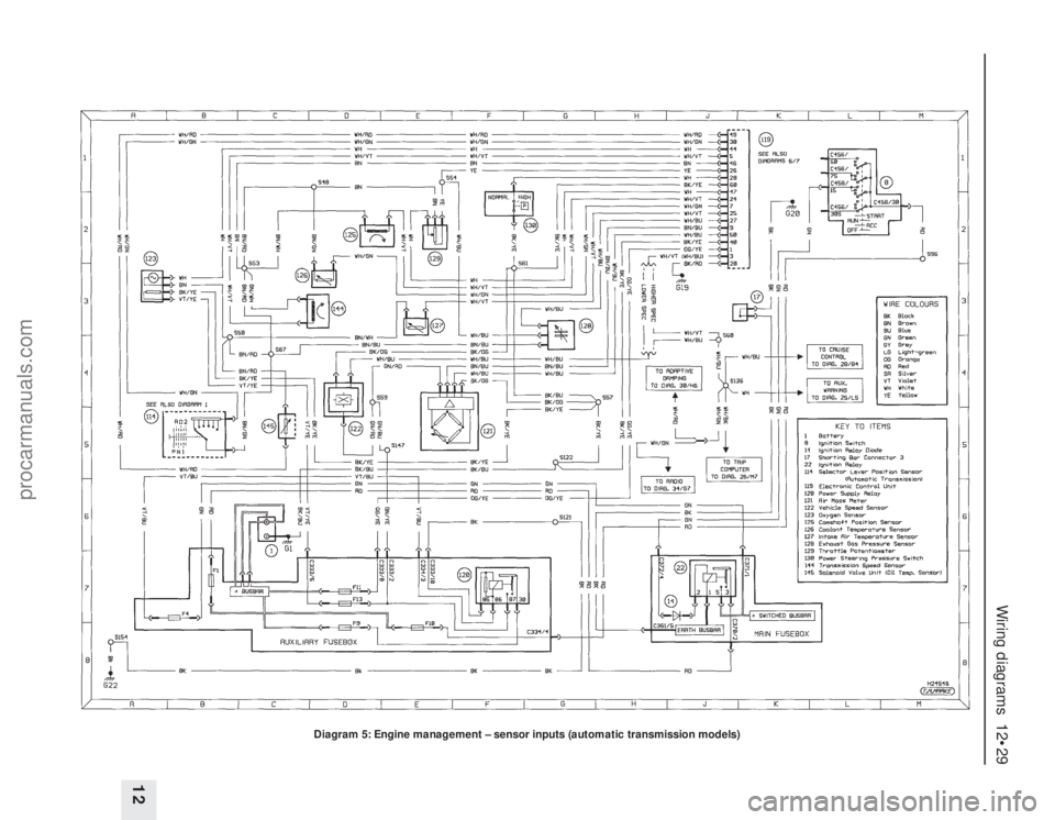
Wiring diagrams 12•29
12
Diagram 5: Engine management – sensor inputs (automatic transmission models)
procarmanuals.com
Page 231 of 279
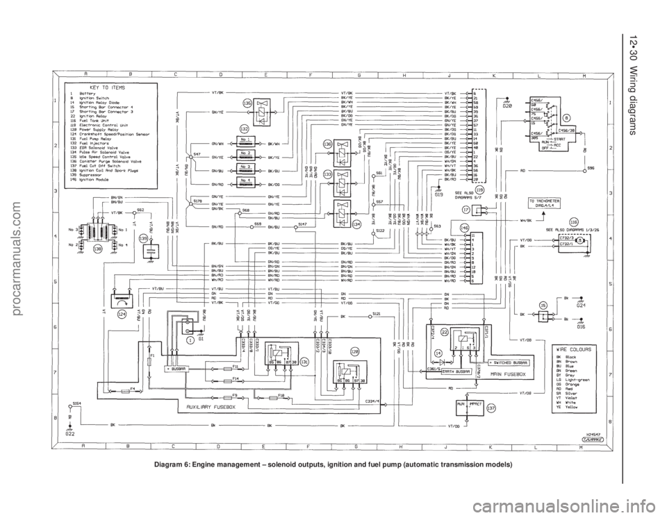
12•30 Wiring diagrams
Diagram 6: Engine management – solenoid outputs, ignition and fuel pump (automatic transmission models)
procarmanuals.com
Page 232 of 279
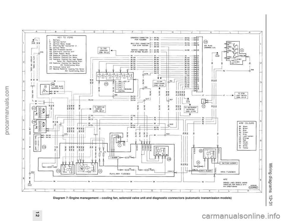
Wiring diagrams 12•31
12
Diagram 7: Engine management – cooling fan, solenoid valve unit and diagnostic connectors (automatic transmission models)
procarmanuals.com
Page 260 of 279
Introduction
A selection of good tools is a fundamental
requirement for anyone contemplating the
maintenance and repair of a motor vehicle.
For the owner who does not possess any,
their purchase will prove a considerable
expense, offsetting some of the savings made
by doing-it-yourself. However, provided that
the tools purchased meet the relevant national
safety standards and are of good quality, they
will last for many years and prove an
extremely worthwhile investment.
To help the average owner to decide which
tools are needed to carry out the various tasks
detailed in this manual, we have compiled
three lists of tools under the following
headings: Maintenance and minor repair,
Repair and overhaul, and Special. Newcomers
to practical mechanics should start off with
the Maintenance and minor repairtool kit, and
confine themselves to the simpler jobs around
the vehicle. Then, as confidence and
experience grow, more difficult tasks can be
undertaken, with extra tools being purchased
as, and when, they are needed. In this way, a
Maintenance and minor repairtool kit can be
built up into a Repair and overhaultool kit over
a considerable period of time, without any
major cash outlays. The experienced do-it-
yourselfer will have a tool kit good enough for
most repair and overhaul procedures, and will
add tools from the Specialcategory when it is
felt that the expense is justified by the amount
of use to which these tools will be put.
Maintenance and minor repair
tool kit
The tools given in this list should be
considered as a minimum requirement if
routine maintenance, servicing and minor
repair operations are to be undertaken. We
recommend the purchase of combination
spanners (ring one end, open-ended the
other); although more expensive than open-
ended ones, they do give the advantages of
both types of spanner.
MCombination spanners:
Metric - 8, 9, 10, 11, 12, 13, 14, 15, 16, 17,
19, 21, 22, 24 & 26 mm
MAdjustable spanner - 35 mm jaw (approx)
MTransmission drain plug key (Allen type)
MSet of feeler gauges
MSpark plug spanner (with rubber insert)
MSpark plug gap adjustment tool
MBrake adjuster spanner (where applicable)
MBrake bleed nipple spanner
MScrewdrivers:
Flat blade - approx 100 mm long x 6 mm dia
Cross blade - approx 100 mm long x
6 mm dia
MCombination pliers
MHacksaw (junior)
MTyre pump
MTyre pressure gauge
MOil can
MOil filter removal tool
MFine emery cloth
MWire brush (small)
MFunnel (medium size)
Repair and overhaul tool kit
These tools are virtually essential for
anyone undertaking any major repairs to a
motor vehicle, and are additional to those
given in the Maintenance and minor repairlist.
Included in this list is a comprehensive set of
sockets. Although these are expensive, they
will be found invaluable as they are so
versatile - particularly if various drives are
included in the set. We recommend the half-
inch square-drive type, as this can be used
with most proprietary torque wrenches. If you
cannot afford a socket set, even bought
piecemeal, then inexpensive tubular box
spanners are a useful alternative.
The tools in this list will occasionally need to
be supplemented by tools from the Special
list:
MSockets (or box spanners) to cover range in
previous list
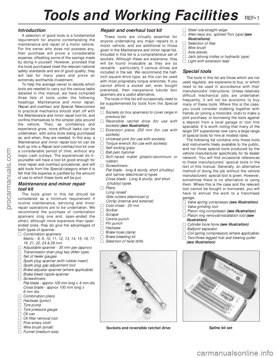
MReversible ratchet drive (for use with
sockets) (see illustration)
MExtension piece, 250 mm (for use with
sockets)
MUniversal joint (for use with sockets)
MTorque wrench (for use with sockets)
MSelf-locking grips
MBall pein hammer
MSoft-faced mallet (plastic/aluminium or
rubber)
MScrewdrivers:
Flat blade - long & sturdy, short (chubby),
and narrow (electrician’s) types
Cross blade - Long & sturdy, and short
(chubby) types
MPliers:
Long-nosed
Side cutters (electrician’s)
Circlip (internal and external)
MCold chisel - 25 mm
MScriber
MScraper
MCentre-punch
MPin punch
MHacksaw
MBrake hose clamp
MBrake bleeding kit
MSelection of twist drillsMSteel rule/straight-edge
MAllen keys (inc. splined/Torx type) (see
illustrations)
MSelection of files
MWire brush
MAxle stands
MJack (strong trolley or hydraulic type)
MLight with extension lead
Special tools
The tools in this list are those which are not
used regularly, are expensive to buy, or which
need to be used in accordance with their
manufacturers’ instructions. Unless relatively
difficult mechanical jobs are undertaken
frequently, it will not be economic to buy
many of these tools. Where this is the case,
you could consider clubbing together with
friends (or joining a motorists’ club) to make a
joint purchase, or borrowing the tools against
a deposit from a local garage or tool hire
specialist. It is worth noting that many of the
larger DIY superstores now carry a large range
of special tools for hire at modest rates.
The following list contains only those tools
and instruments freely available to the public,
and not those special tools produced by the
vehicle manufacturer specifically for its dealer
network. You will find occasional references
to these manufacturers’ special tools in the
text of this manual. Generally, an alternative
method of doing the job without the vehicle
manufacturers’ special tool is given. However,
sometimes there is no alternative to using
them. Where this is the case and the relevant
tool cannot be bought or borrowed, you will
have to entrust the work to a franchised
garage.
MValve spring compressor (see illustration)
MValve grinding tool
MPiston ring compressor (see illustration)
MPiston ring removal/installation tool (see
illustration)
MCylinder bore hone (see illustration)
MBalljoint separator
MCoil spring compressors (where applicable)
MTwo/three-legged hub and bearing puller
(see illustration)
REF•1
Sockets and reversible ratchet driveSpline bit set
Tools and Working Facilities
procarmanuals.com