differential FORD MONDEO 1993 Service Repair Manual
[x] Cancel search | Manufacturer: FORD, Model Year: 1993, Model line: MONDEO, Model: FORD MONDEO 1993Pages: 279, PDF Size: 12.71 MB
Page 137 of 279
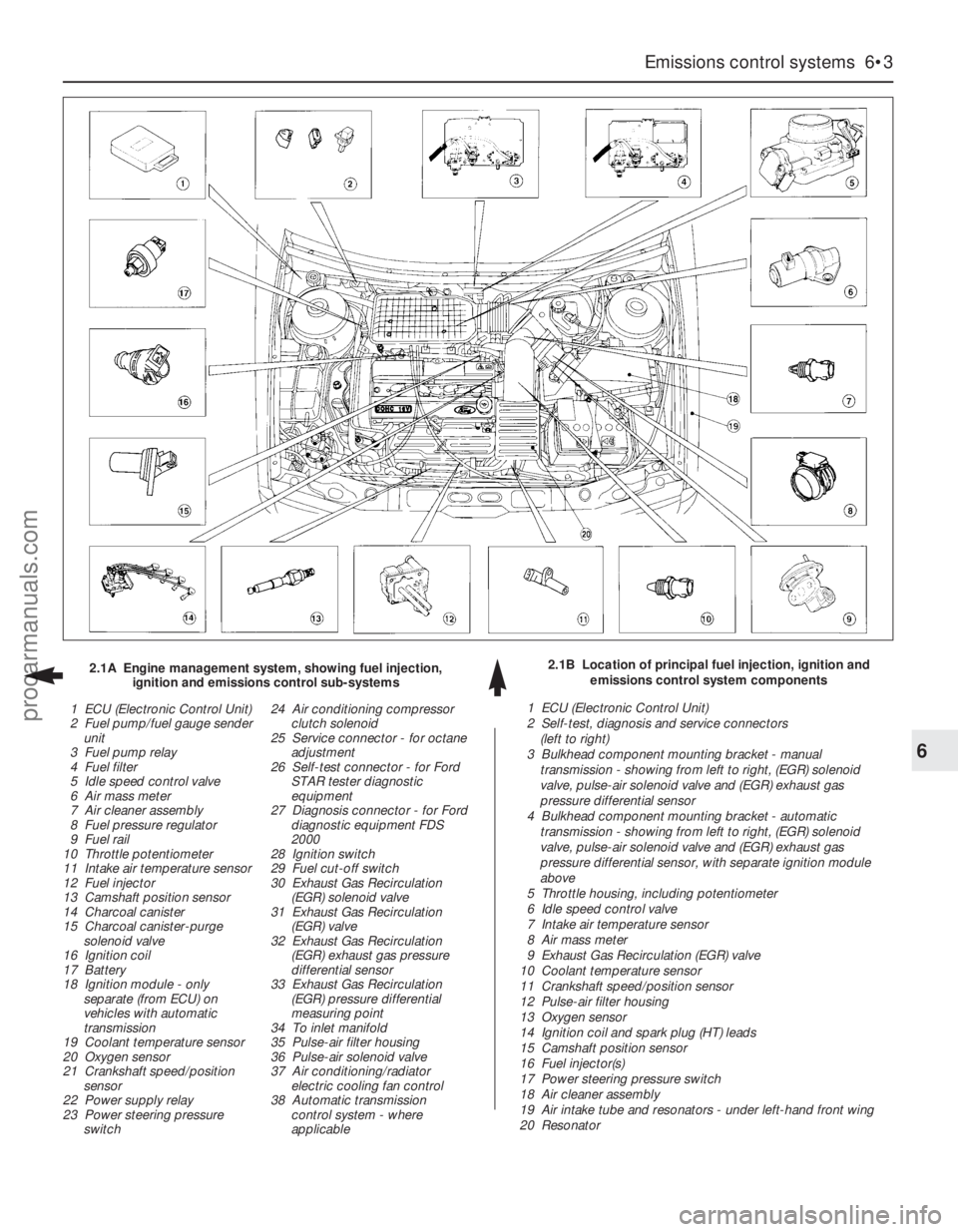
Emissions control systems 6•3
6
2.1B Location of principal fuel injection, ignition and
emissions control system components 2.1A Engine management system, showing fuel injection,
ignition and emissions control sub-systems
1 ECU (Electronic Control Unit)
2 Fuel pump/fuel gauge sender
unit
3 Fuel pump relay
4 Fuel filter
5 Idle speed control valve
6 Air mass meter
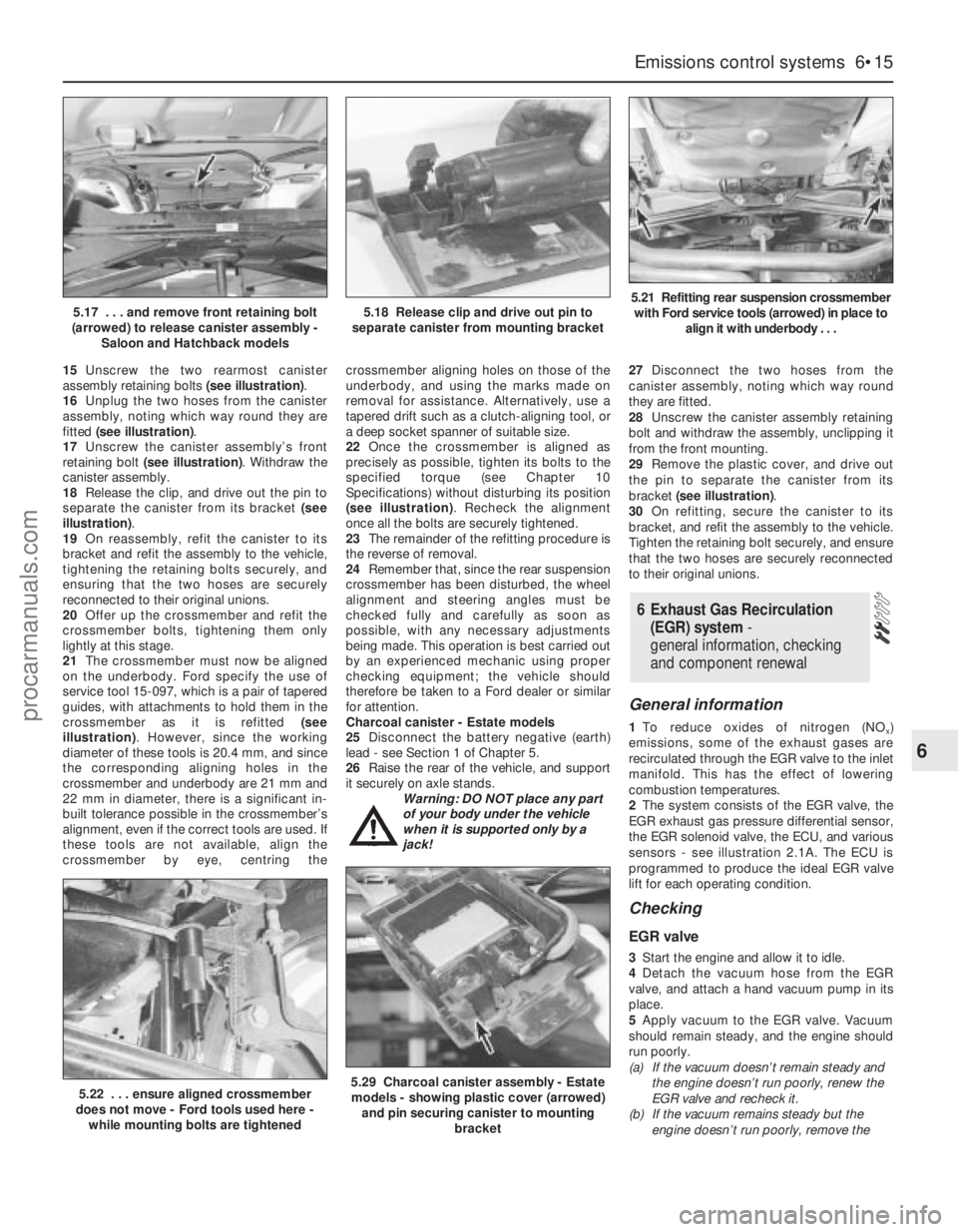
7 Air cleaner assembly
8 Fuel pressure regulator
9 Fuel rail
10 Throttle potentiometer
11 Intake air temperature sensor
12 Fuel injector
13 Camshaft position sensor
14 Charcoal canister
15 Charcoal canister-purge
solenoid valve
16 Ignition coil
17 Battery
18 Ignition module - only
separate (from ECU) on
vehicles with automatic
transmission
19 Coolant temperature sensor
20 Oxygen sensor
21 Crankshaft speed/position
sensor
22 Power supply relay
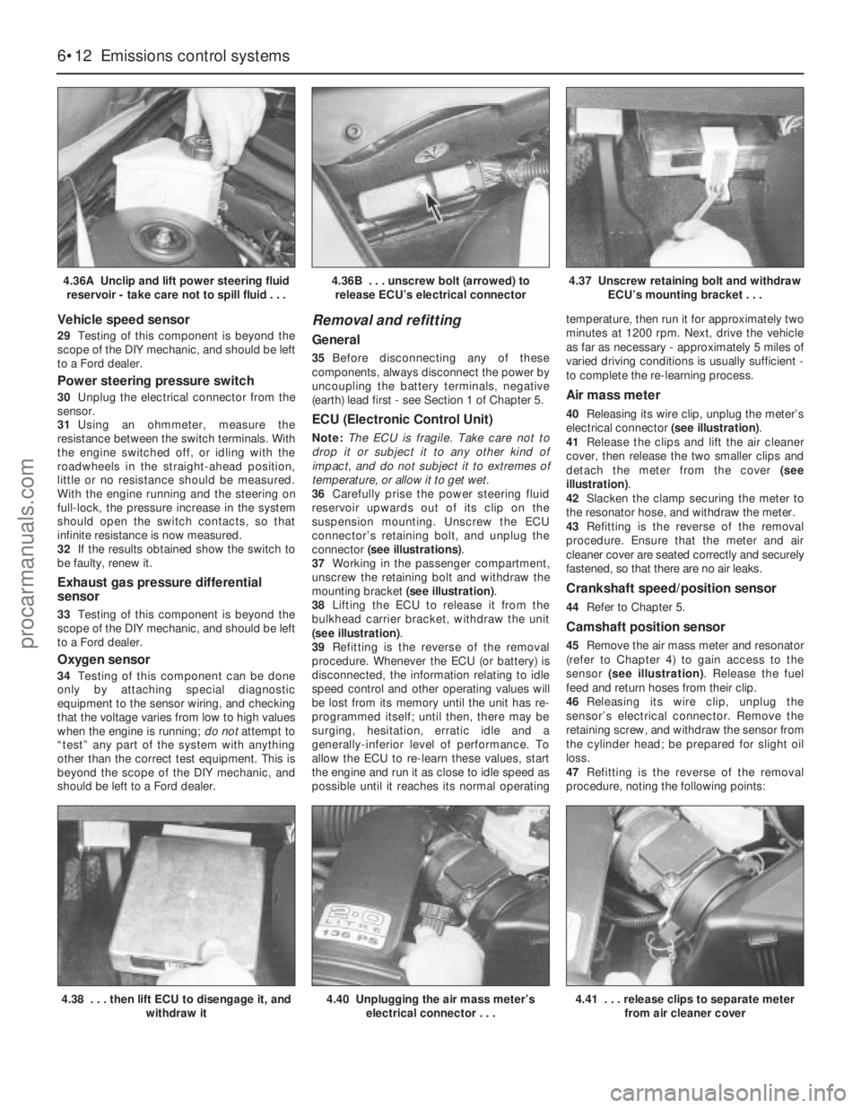
23 Power steering pressure
switch24 Air conditioning compressor
clutch solenoid
25 Service connector - for octane
adjustment
26 Self-test connector - for Ford
STAR tester diagnostic
equipment
27 Diagnosis connector - for Ford
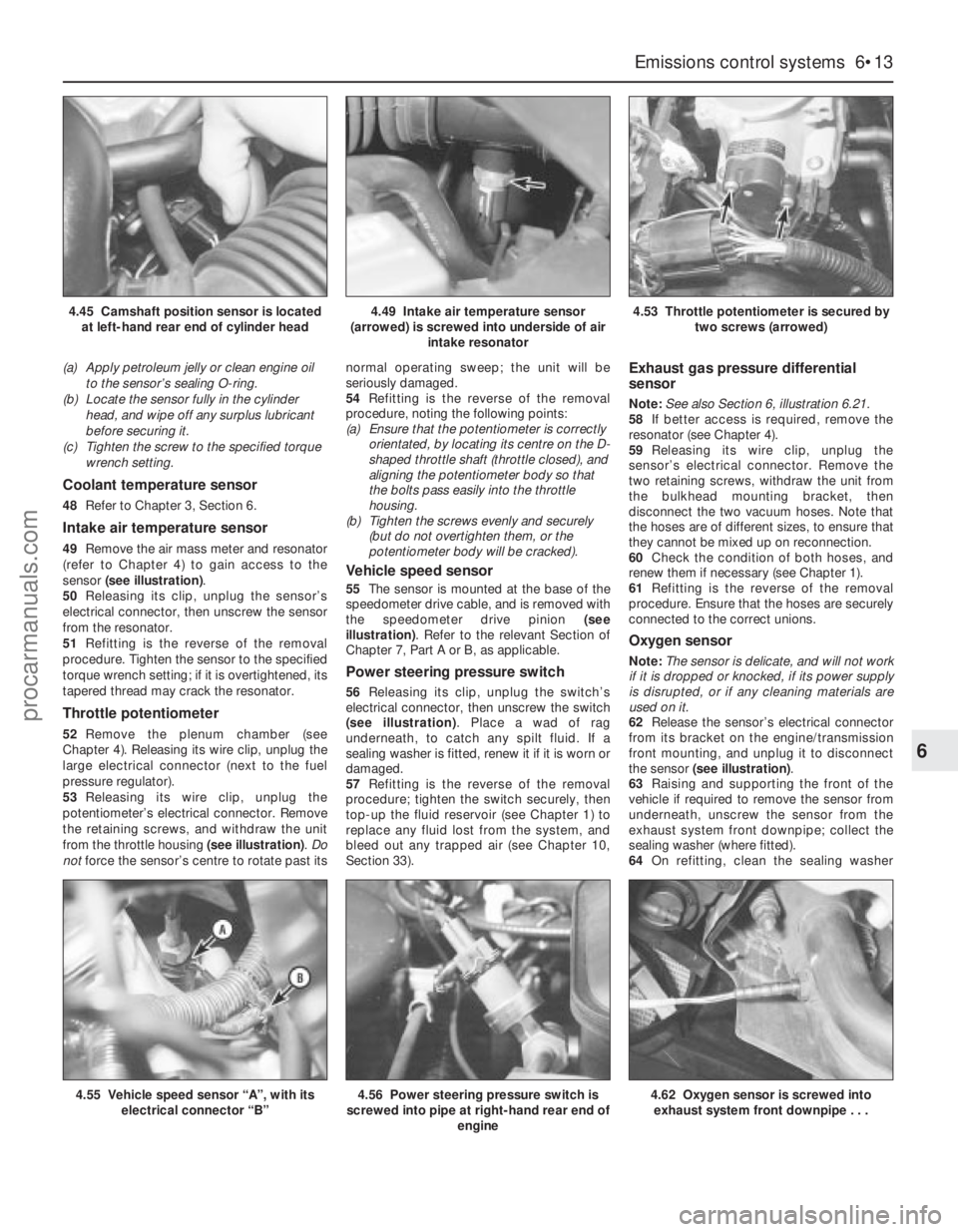
diagnostic equipment FDS
2000
28 Ignition switch
29 Fuel cut-off switch
30 Exhaust Gas Recirculation
(EGR) solenoid valve
31 Exhaust Gas Recirculation
(EGR) valve
32 Exhaust Gas Recirculation
(EGR) exhaust gas pressure
differential sensor
33 Exhaust Gas Recirculation
(EGR) pressure differential
measuring point
34 To inlet manifold
35 Pulse-air filter housing
36 Pulse-air solenoid valve
37 Air conditioning/radiator
electric cooling fan control
38 Automatic transmission
control system - where
applicable1 ECU (Electronic Control Unit)
2 Self-test, diagnosis and service connectors
(left to right)
3 Bulkhead component mounting bracket - manual
transmission - showing from left to right, (EGR) solenoid
valve, pulse-air solenoid valve and (EGR) exhaust gas
pressure differential sensor
4 Bulkhead component mounting bracket - automatic
transmission - showing from left to right, (EGR) solenoid
valve, pulse-air solenoid valve and (EGR) exhaust gas
pressure differential sensor, with separate ignition module
above
5 Throttle housing, including potentiometer
6 Idle speed control valve
7 Intake air temperature sensor
8 Air mass meter
9 Exhaust Gas Recirculation (EGR) valve
10 Coolant temperature sensor
11 Crankshaft speed/position sensor
12 Pulse-air filter housing
13 Oxygen sensor
14 Ignition coil and spark plug (HT) leads
15 Camshaft position sensor
16 Fuel injector(s)
17 Power steering pressure switch
18 Air cleaner assembly
19 Air intake tube and resonators - under left-hand front wing
20 Resonator
procarmanuals.com
Page 139 of 279
coolant or EGR pipes, etc. In almost all cases,
damage of this sort is caused in the first
instance by incorrect routing on reassembly
after previous work has been carried out (see
the note at the beginning of this sub-Section).
6Obviously wires can break or short together
inside the insulation so that no visible
evidence betrays the fault, but this usually
only occurs where the wiring loom has been
incorrectly routed so that it is stretched taut or
kinked sharply; either of these conditions
should be obvious on even a casual
inspection. If this is thought to have happened
and the fault proves elusive, the suspect
section of wiring should be checked very
carefully during the more detailed checks
which follow.
7Depending on the extent of the problem,
damaged wiring may be repaired by rejoining
the break or splicing-in a new length of wire,
using solder to ensure a good connection,
and remaking the insulation with adhesive
insulating tape or heat-shrink tubing, as
desired. If the damage is extensive, given the
implications for the vehicle’s future reliability,
the best long-term answer may well be to
renew that entire section of the loom, however
expensive this may appear.
8When the actual damage has been
repaired, ensure that the wiring loom is
rerouted correctly, so that it is clear of other
components, is not stretched or kinked, and is
secured out of harm’s way using the plastic
clips, guides and ties provided.
9Check all electrical connectors, ensuring
that they are clean, securely fastened, and
that each is locked by its plastic tabs or wire
clip, as appropriate. If any connector shows
external signs of corrosion (accumulations of
white or green deposits, or streaks of “rust”),
or if any is thought to be dirty, it must be
unplugged and cleaned using electrical
contact cleaner. If the connector pins are
severely corroded, the connector must be
renewed; note that this may mean the renewalof that entire section of the loom - see your
local Ford dealer for details.
10If the cleaner completely removes the
corrosion to leave the connector in a
satisfactory condition, it would be wise to
pack the connector with a suitable material
which will exclude dirt and moisture, and
prevent the corrosion from occurring again; a
Ford dealer may be able to recommend a
suitable product. Note:The system’s
connectors use gold-plated pins, which must
notbe mixed with the older tin-plated types
(readily identifiable from the different colour) if
a component is renewed, nor must the lithium
grease previously used to protect tin-plated
pins be used on gold-plated connectors.
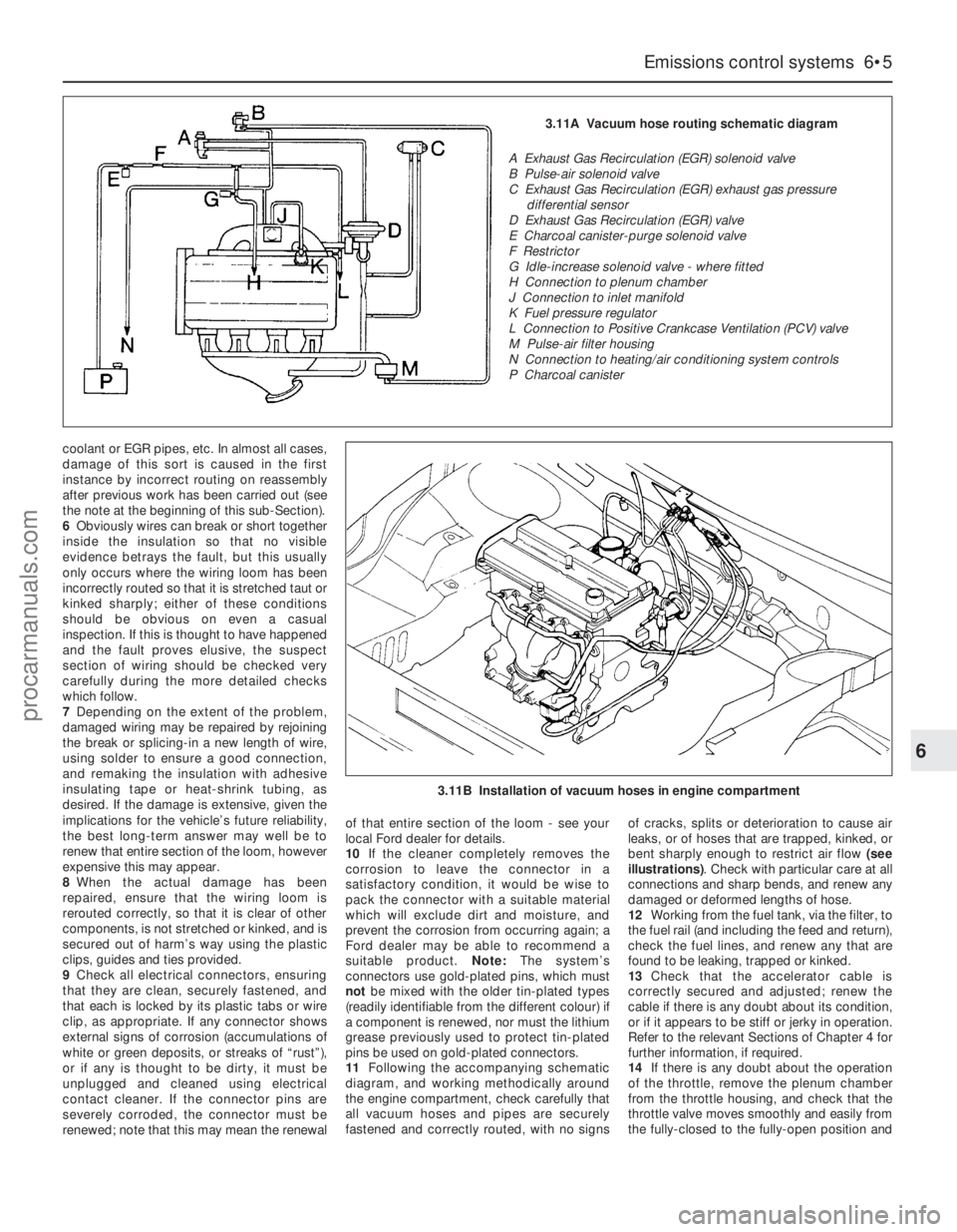
11Following the accompanying schematic
diagram, and working methodically around
the engine compartment, check carefully that
all vacuum hoses and pipes are securely
fastened and correctly routed, with no signsof cracks, splits or deterioration to cause air
leaks, or of hoses that are trapped, kinked, or
bent sharply enough to restrict air flow (see
illustrations). Check with particular care at all
connections and sharp bends, and renew any
damaged or deformed lengths of hose.
12Working from the fuel tank, via the filter, to
the fuel rail (and including the feed and return),
check the fuel lines, and renew any that are
found to be leaking, trapped or kinked.
13Check that the accelerator cable is
correctly secured and adjusted; renew the
cable if there is any doubt about its condition,
or if it appears to be stiff or jerky in operation.
Refer to the relevant Sections of Chapter 4 for
further information, if required.
14If there is any doubt about the operation
of the throttle, remove the plenum chamber
from the throttle housing, and check that the
throttle valve moves smoothly and easily from
the fully-closed to the fully-open position and
Emissions control systems 6•5
6
3.11A Vacuum hose routing schematic diagram
A Exhaust Gas Recirculation (EGR) solenoid valve
B Pulse-air solenoid valve
C Exhaust Gas Recirculation (EGR) exhaust gas pressure
differential sensor
D Exhaust Gas Recirculation (EGR) valve
E Charcoal canister-purge solenoid valve
F Restrictor
G Idle-increase solenoid valve - where fitted
H Connection to plenum chamber
J Connection to inlet manifold
K Fuel pressure regulator
L Connection to Positive Crankcase Ventilation (PCV) valve
M Pulse-air filter housing
N Connection to heating/air conditioning system controls
P Charcoal canister
3.11B Installation of vacuum hoses in engine compartment
procarmanuals.com
Page 142 of 279
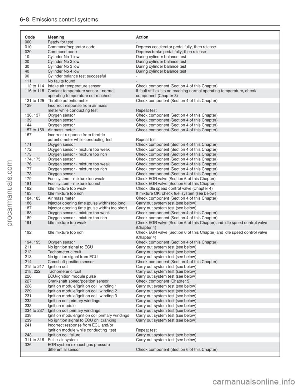
6•8 Emissions control systems
Code Meaning Action
000 Ready for test -
010 Command/separator code Depress accelerator pedal fully, then release
020 Command code Depress brake pedal fully, then release
10 Cylinder No 1 low During cylinder balance test
20 Cylinder No 2 low During cylinder balance test
30 Cylinder No 3 low During cylinder balance test
40 Cylinder No 4 low During cylinder balance test
90 Cylinder balance test successful -
111 No faults found -
112 to 114 Intake air temperature sensor Check component (Section 4 of this Chapter)116 to 118 Coolant temperature sensor - normal If fault still exists on reaching normal operating temperature, check
operating temperature not reached component (Chapter 3)
121 to 125 Throttle potentiometer Check component (Section 4 of this Chapter)129 Incorrect response from air mass
meter while conducting test Repeat test
136, 137 Oxygen sensor Check component (Section 4 of this Chapter)
139 Oxygen sensor Check component (Section 4 of this Chapter)
144 Oxygen sensor Check component (Section 4 of this Chapter)
157 to 159 Air mass meter Check component (Section 4 of this Chapter)
167 Incorrect response from throttle
potentiometer while conducting test Repeat test
171 Oxygen sensor Check component (Section 4 of this Chapter)
172 Oxygen sensor - mixture too weak Check component (Section 4 of this Chapter)
173 Oxygen sensor - mixture too rich Check component (Section 4 of this Chapter)
174, 175 Oxygen sensor Check component (Section 4 of this Chapter)
176 Oxygen sensor - mixture too weak Check component (Section 4 of this Chapter)
177 Oxygen sensor - mixture too rich Check component (Section 4 of this Chapter)
178 Oxygen sensor Check component (Section 4 of this Chapter)
179 Fuel system - mixture too weak Check EGR valve (Section 6 of this Chapter)
181 Fuel system - mixture too rich Check EGR valve (Section 6 of this Chapter)
182 Idle mixture too weak Check idle speed control valve (Chapter 4)
183 Idle mixture too rich If mixture OK, check fuel system (see below)
184, 185 Air mass meter Check component (Section 4 of this Chapter)
186 Injector opening time (pulse width) too long Carry out system test (see below)
187 Injector opening time (pulse width) too short Carry out system test (see below)
188 Oxygen sensor - mixture too weak Check component (Section 4 of this Chapter)
189 Oxygen sensor - mixture too rich Check component (Section 4 of this Chapter)191 Idle mixture too weak Check EGR valve (Section 6 of this Chapter) and idle speed control valve
(Chapter 4)
192 Idle mixture too rich Check EGR valve (Section 6 of this Chapter) and idle speed control valve
(Chapter 4)
194, 195 Oxygen sensor Check component (Section 4 of this Chapter)
211 No ignition signal to ECU Carry out system test (see below)
212 Tachometer circuit Carry out system test (see below)
213 No ignition signal from ECU Carry out system test (see below)
214 Camshaft position sensor Check component (Section 4 of this Chapter)
215 to 217 Ignition coil Carry out system test (see below)
218, 222 Tachometer circuit Carry out system test (see below)
226 ECU/ignition module pulse Carry out system test (see below)
227 Crankshaft speed/position sensor Check component (Chapter 5)
228 Ignition module/ignition coil winding 1 Carry out system test (see below)
229 Ignition module/ignition coil winding 2 Carry out system test (see below)
231 Ignition module/ignition coil winding 3 Carry out system test (see below)
232 Ignition coil primary windings Carry out system test (see below)
233 Ignition module Carry out system test (see below)
234 to 237 Ignition coil primary windings Carry out system test (see below)
238 Ignition module/ignition coil primary windings Carry out system test (see below)
239 No ignition signal to ECU on cranking Carry out system test (see below)
241 Incorrect response from ECU and/or
ignition module while conducting test Repeat test
243 Ignition coil failure Carry out system test (see below)
311 to 316 Pulse-air system Carry out system test (see below)326 EGR system exhaust gas pressure
differential sensor Check component (Section 6 of this Chapter)
procarmanuals.com
Page 143 of 279
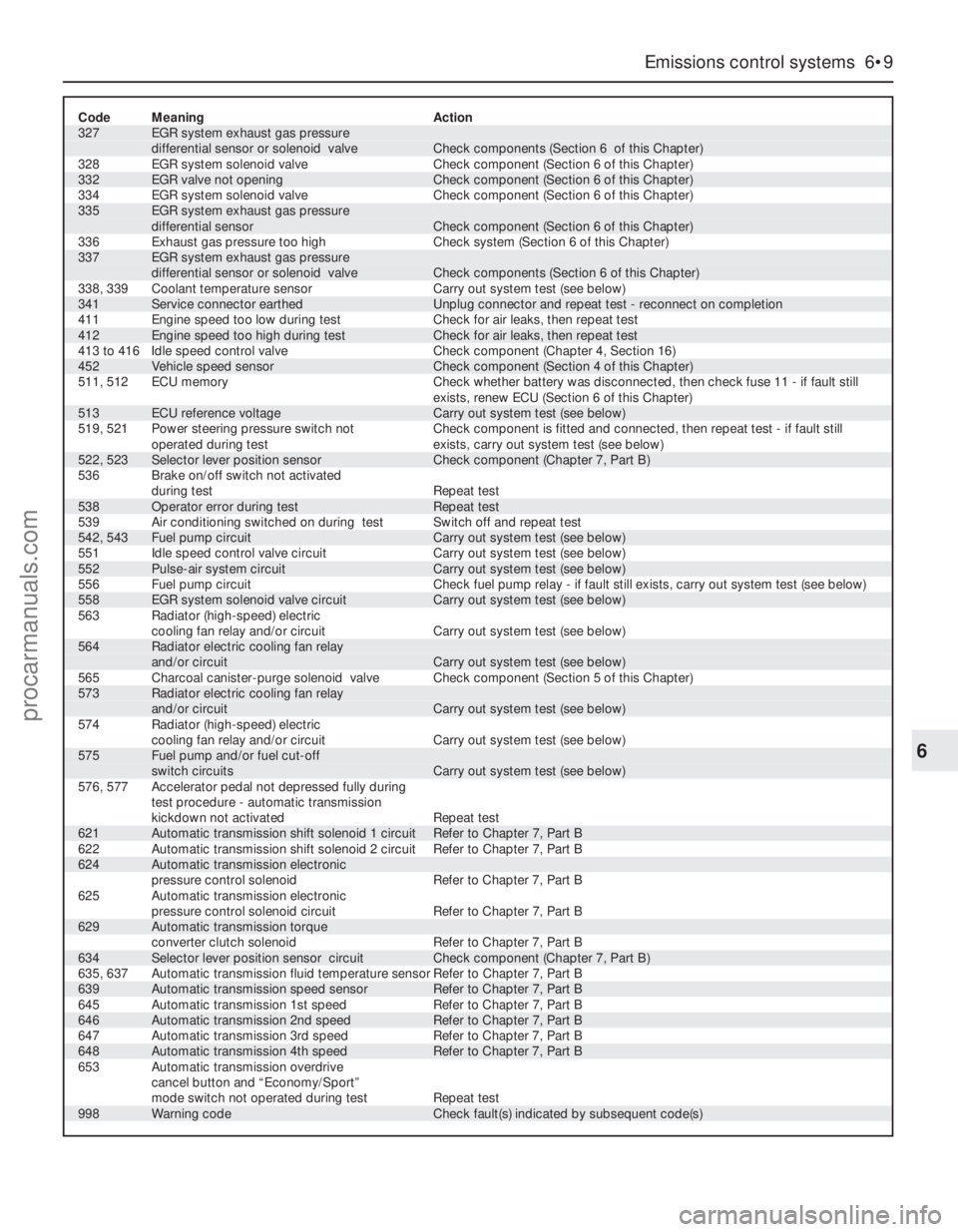
Code Meaning Action327 EGR system exhaust gas pressure
differential sensor or solenoid valve Check components (Section 6 of this Chapter)
328 EGR system solenoid valve Check component (Section 6 of this Chapter)
332 EGR valve not opening Check component (Section 6 of this Chapter)
334 EGR system solenoid valve Check component (Section 6 of this Chapter)335 EGR system exhaust gas pressure
differential sensor Check component (Section 6 of this Chapter)
336 Exhaust gas pressure too high Check system (Section 6 of this Chapter)337 EGR system exhaust gas pressure
differential sensor or solenoid valve Check components (Section 6 of this Chapter)
338, 339 Coolant temperature sensor Carry out system test (see below)
341 Service connector earthed Unplug connector and repeat test - reconnect on completion
411 Engine speed too low during test Check for air leaks, then repeat test
412 Engine speed too high during test Check for air leaks, then repeat test
413 to 416 Idle speed control valve Check component (Chapter 4, Section 16)
452 Vehicle speed sensor Check component (Section 4 of this Chapter)
511, 512 ECU memory Check whether battery was disconnected, then check fuse 11 - if fault still
exists, renew ECU (Section 6 of this Chapter)
513 ECU reference voltage Carry out system test (see below)
519, 521 Power steering pressure switch not Check component is fitted and connected, then repeat test - if fault still
operated during test exists, carry out system test (see below)
522, 523 Selector lever position sensor Check component (Chapter 7, Part B)
536 Brake on/off switch not activated
during test Repeat test
538 Operator error during test Repeat test
539 Air conditioning switched on during test Switch off and repeat test
542, 543 Fuel pump circuit Carry out system test (see below)
551 Idle speed control valve circuit Carry out system test (see below)
552 Pulse-air system circuit Carry out system test (see below)
556 Fuel pump circuit Check fuel pump relay - if fault still exists, carry out system test (see below)
558 EGR system solenoid valve circuit Carry out system test (see below)
563 Radiator (high-speed) electric
cooling fan relay and/or circuit Carry out system test (see below)564 Radiator electric cooling fan relay
and/or circuit Carry out system test (see below)
565 Charcoal canister-purge solenoid valve Check component (Section 5 of this Chapter)573 Radiator electric cooling fan relay
and/or circuit Carry out system test (see below)
574 Radiator (high-speed) electric
cooling fan relay and/or circuit Carry out system test (see below)575 Fuel pump and/or fuel cut-off
switch circuits Carry out system test (see below)
576, 577 Accelerator pedal not depressed fully during
test procedure - automatic transmission
kickdown not activated Repeat test
621 Automatic transmission shift solenoid 1 circuit Refer to Chapter 7, Part B
622 Automatic transmission shift solenoid 2 circuit Refer to Chapter 7, Part B
624 Automatic transmission electronic
pressure control solenoid Refer to Chapter 7, Part B
625 Automatic transmission electronic
pressure control solenoid circuit Refer to Chapter 7, Part B
629 Automatic transmission torque
converter clutch solenoid Refer to Chapter 7, Part B
634 Selector lever position sensor circuit Check component (Chapter 7, Part B)
635, 637 Automatic transmission fluid temperature sensor Refer to Chapter 7, Part B
639 Automatic transmission speed sensor Refer to Chapter 7, Part B
645 Automatic transmission 1st speed Refer to Chapter 7, Part B
646 Automatic transmission 2nd speed Refer to Chapter 7, Part B
647 Automatic transmission 3rd speed Refer to Chapter 7, Part B
648 Automatic transmission 4th speed Refer to Chapter 7, Part B
653 Automatic transmission overdrive
cancel button and “Economy/Sport”
mode switch not operated during test Repeat test
998 Warning code Check fault(s) indicated by subsequent code(s)
Emissions control systems 6•9
6
procarmanuals.com
Page 145 of 279
passes the sensor tip, a signal is generated,
which is used by the ECU to determine engine
speed.
4The ridge between the 35th and 36th holes
(corresponding to 90° BTDC) is missing - this
step in the incoming signals is used by the
ECU to determine crankshaft (ie, piston)
position.
Camshaft position sensor
5This is bolted to the rear left-hand end of
the cylinder head, to register with a lobe on
the inlet camshaft. It functions in the same
way as the crankshaft speed/position sensor,
producing a series of pulses (corresponding
to No 1 cylinder at 46° ATDC); this gives the
ECU a reference point, to enable it to
determine the firing order, and operate the
injectors in the appropriate sequence.
Coolant temperature sensor
6This component, which is screwed into the
top of the thermostat housing, is an NTC
(Negative Temperature Coefficient) thermistor
- that is, a semi-conductor whose electrical
resistance decreases as its temperature
increases. It provides the ECU with a
constantly-varying (analogue) voltage signal,
corresponding to the temperature of the
engine coolant. This is used to refine the
calculations made by the ECU, when
determining the correct amount of fuel
required to achieve the ideal air/fuel mixture
ratio.
Intake air temperature sensor
7This component, which is screwed into the
underside of the air intake resonator, is also an
NTC thermistor - see the previous paragraph -
providing the ECU with a signal corresponding
to the temperature of air passing into the
engine. This is used to refine the calculations
made by the ECU, when determining the
correct amount of fuel required to achieve the
ideal air/fuel mixture ratio.
Throttle potentiometer
8This is mounted on the end of the throttle
valve spindle, to provide the ECU with a
constantly-varying (analogue) voltage signal
corresponding to the throttle opening. This
allows the ECU to register the driver’s input
when determining the amount of fuel required
by the engine.
Vehicle speed sensor
9This component is a Hall-effect generator,
mounted on the transmission’s speedometer
drive. It supplies the ECU with a series of
pulses corresponding to the vehicle’s road
speed, enabling the ECU to control features
such as the fuel shut-off on the overrun, and
to provide information for the trip computer,
adaptive damping and cruise control systems
(where fitted).
Power steering pressure switch
10This is a pressure-operated switch,
screwed into the power steering system’shigh-pressure pipe. Its contacts are normally
closed, opening when the system reaches the
specified pressure - on receiving this signal,
the ECU increases the idle speed, to
compensate for the additional load on the
engine.
Exhaust gas pressure differential
sensor
11This component measures the difference
in pressure of the exhaust gases across a
venturi (restriction) in the Exhaust Gas
Recirculation (EGR) system’s pipe, and sends
the ECU a voltage signal corresponding to the
pressure difference.
Oxygen sensor
12The oxygen sensor in the exhaust system
provides the ECU with constant feedback -
“closed-loop” control - which enables it to
adjust the mixture to provide the best possible
conditions for the catalytic converter to
operate.
13The sensor has a built-in heating element
which is controlled by the ECU, in order to
bring the sensor’s tip to an efficient operating
temperature as rapidly as possible. The
sensor’s tip is sensitive to oxygen, and sends
the ECU a varying voltage depending on the
amount of oxygen in the exhaust gases. If the
intake air/fuel mixture is too rich, the exhaust
gases are low in oxygen, so the sensor sends
a low-voltage signal, the voltage rising as the
mixture weakens and the amount of oxygen in
the exhaust gases rises. Peak conversion
efficiency of all major pollutants occurs if the
intake air/fuel mixture is maintained at the
chemically-correct ratio for the complete
combustion of petrol, of 14.7 parts (by weight)
of air to 1 part of fuel (the “stoichiometric”
ratio). The sensor output voltage alters sharply
around this point, the ECU using the signal
change as a reference point, and correcting
the air/fuel mixture by altering the fuel injector
pulse width.
Air conditioning system
14Two pressure-operated switches and the
compressor clutch solenoid are connected to
the ECU, to enable it to determine how the
system is operating. The ECU can increase
idle speed or switch off the system, as
necessary, so that normal vehicle operation
and driveability are not impaired. See Chapter
3 for further details, but note that diagnosis
and repair should be left to a dealer service
department or air conditioning specialist.
Automatic transmission
15In addition to the driver’s controls, the
transmission has a speed sensor, a fluid
temperature sensor (built into the solenoid
valve unit), and a selector lever position
sensor. All of these are connected to the ECU,
to enable it to control the transmission
through the solenoid valve unit. See Part B of
Chapter 7 for further details.
Testing
ECU (Electronic Control Unit)
16 Do notattempt to “test” the ECU with any
kind of equipment. If it is thought to be faulty,
take the vehicle to a Ford dealer for the entire
electronic control system to be checked using
the proper diagnostic equipment. Only if all
other possibilities have been eliminated should
the ECU be considered at fault, and replaced.
Air mass meter
17Testing of this component is beyond the
scope of the DIY mechanic, and should be left
to a Ford dealer.
Crankshaft speed/position sensor
18Unplug the electrical connector from the
sensor.
19Using an ohmmeter, measure the
resistance between the sensor terminals.
Compare this reading to the one listed in the
Specifications Section at the beginning of this
Chapter. If the indicated resistance is not
within the specified range, renew the sensor.
20Plug in the sensor’s electrical connector
on completion.
Camshaft position sensor
21The procedure is as described in
paragraphs 18 to 20 above.
Coolant temperature sensor
22Refer to Chapter 3.
Intake air temperature sensor
23Unplug the electrical connector from the
sensor.
24Using an ohmmeter, measure the
resistance between the sensor terminals.
Depending on the temperature of the sensor
tip, the resistance measured will vary, but it
should be within the broad limits given in the
Specifications Section of this Chapter. If the
sensor’s temperature is varied - by placing it
in a freezer for a while, or by warming it gently
- its resistance should alter accordingly.
25If the results obtained show the sensor to
be faulty, renew it.
Throttle potentiometer
26Remove the plenum chamber (see
Chapter 4) and unplug the potentiometer’s
electrical connector.
27Using an ohmmeter, measure the
resistance between the unit’s terminals - first
between the centre terminal and one of the
outer two, then from the centre to the
remaining outer terminal. The resistance
should be within the limits given in the
Specifications Section of this Chapter, and
should alter smoothlyas the throttle valve is
moved from the fully-closed (idle speed)
position to fully open and back again.
28If the resistance measured is significantly
different from the specified value, if there are
any breaks in continuity, or if the reading
fluctuates erratically as the throttle is
operated, the potentiometer is faulty, and
must be renewed.
Emissions control systems 6•11
6
procarmanuals.com
Page 146 of 279
Vehicle speed sensor
29Testing of this component is beyond the
scope of the DIY mechanic, and should be left
to a Ford dealer.
Power steering pressure switch
30Unplug the electrical connector from the
sensor.
31Using an ohmmeter, measure the
resistance between the switch terminals. With
the engine switched off, or idling with the
roadwheels in the straight-ahead position,
little or no resistance should be measured.
With the engine running and the steering on
full-lock, the pressure increase in the system
should open the switch contacts, so that
infinite resistance is now measured.
32If the results obtained show the switch to
be faulty, renew it.
Exhaust gas pressure differential
sensor
33Testing of this component is beyond the
scope of the DIY mechanic, and should be left
to a Ford dealer.
Oxygen sensor
34Testing of this component can be done
only by attaching special diagnostic
equipment to the sensor wiring, and checking
that the voltage varies from low to high values
when the engine is running; do notattempt to
“test” any part of the system with anything
other than the correct test equipment. This is
beyond the scope of the DIY mechanic, and
should be left to a Ford dealer.
Removal and refitting
General
35Before disconnecting any of these
components, always disconnect the power by
uncoupling the battery terminals, negative
(earth) lead first - see Section 1 of Chapter 5.
ECU (Electronic Control Unit)
Note:The ECU is fragile. Take care not to
drop it or subject it to any other kind of
impact, and do not subject it to extremes of
temperature, or allow it to get wet.
36Carefully prise the power steering fluid
reservoir upwards out of its clip on the
suspension mounting. Unscrew the ECU
connector’s retaining bolt, and unplug the
connector (see illustrations).
37Working in the passenger compartment,
unscrew the retaining bolt and withdraw the
mounting bracket (see illustration).
38Lifting the ECU to release it from the
bulkhead carrier bracket, withdraw the unit
(see illustration).
39Refitting is the reverse of the removal
procedure. Whenever the ECU (or battery) is
disconnected, the information relating to idle
speed control and other operating values will
be lost from its memory until the unit has re-
programmed itself; until then, there may be
surging, hesitation, erratic idle and a
generally-inferior level of performance. To
allow the ECU to re-learn these values, start
the engine and run it as close to idle speed as
possible until it reaches its normal operatingtemperature, then run it for approximately two
minutes at 1200 rpm. Next, drive the vehicle
as far as necessary - approximately 5 miles of
varied driving conditions is usually sufficient -
to complete the re-learning process.
Air mass meter
40Releasing its wire clip, unplug the meter’s
electrical connector (see illustration).
41Release the clips and lift the air cleaner
cover, then release the two smaller clips and
detach the meter from the cover (see
illustration).
42Slacken the clamp securing the meter to
the resonator hose, and withdraw the meter.
43Refitting is the reverse of the removal
procedure. Ensure that the meter and air
cleaner cover are seated correctly and securely
fastened, so that there are no air leaks.
Crankshaft speed/position sensor
44Refer to Chapter 5.
Camshaft position sensor
45Remove the air mass meter and resonator
(refer to Chapter 4) to gain access to the
sensor (see illustration). Release the fuel
feed and return hoses from their clip.
46Releasing its wire clip, unplug the
sensor’s electrical connector. Remove the
retaining screw, and withdraw the sensor from
the cylinder head; be prepared for slight oil
loss.
47Refitting is the reverse of the removal
procedure, noting the following points:
6•12 Emissions control systems
4.36A Unclip and lift power steering fluid
reservoir - take care not to spill fluid . . .4.36B . . . unscrew bolt (arrowed) to
release ECU’s electrical connector4.37 Unscrew retaining bolt and withdraw
ECU’s mounting bracket . . .
4.40 Unplugging the air mass meter’s
electrical connector . . .4.38 . . . then lift ECU to disengage it, and
withdraw it4.41 . . . release clips to separate meter
from air cleaner cover
procarmanuals.com
Page 147 of 279
(a) Apply petroleum jelly or clean engine oil
to the sensor’s sealing O-ring.
(b) Locate the sensor fully in the cylinder
head, and wipe off any surplus lubricant
before securing it.
(c) Tighten the screw to the specified torque
wrench setting.
Coolant temperature sensor
48Refer to Chapter 3, Section 6.
Intake air temperature sensor
49Remove the air mass meter and resonator
(refer to Chapter 4) to gain access to the
sensor (see illustration).
50Releasing its clip, unplug the sensor’s
electrical connector, then unscrew the sensor
from the resonator.
51Refitting is the reverse of the removal
procedure. Tighten the sensor to the specified
torque wrench setting; if it is overtightened, its
tapered thread may crack the resonator.
Throttle potentiometer
52Remove the plenum chamber (see
Chapter 4). Releasing its wire clip, unplug the
large electrical connector (next to the fuel
pressure regulator).
53Releasing its wire clip, unplug the
potentiometer’s electrical connector. Remove
the retaining screws, and withdraw the unit
from the throttle housing (see illustration). Do
notforce the sensor’s centre to rotate past itsnormal operating sweep; the unit will be
seriously damaged.
54Refitting is the reverse of the removal
procedure, noting the following points:
(a) Ensure that the potentiometer is correctly
orientated, by locating its centre on the D-
shaped throttle shaft (throttle closed), and
aligning the potentiometer body so that
the bolts pass easily into the throttle
housing.
(b) Tighten the screws evenly and securely
(but do not overtighten them, or the
potentiometer body will be cracked).
Vehicle speed sensor
55The sensor is mounted at the base of the
speedometer drive cable, and is removed with
the speedometer drive pinion (see
illustration). Refer to the relevant Section of
Chapter 7, Part A or B, as applicable.
Power steering pressure switch
56Releasing its clip, unplug the switch’s
electrical connector, then unscrew the switch
(see illustration). Place a wad of rag
underneath, to catch any spilt fluid. If a
sealing washer is fitted, renew it if it is worn or
damaged.
57Refitting is the reverse of the removal
procedure; tighten the switch securely, then
top-up the fluid reservoir (see Chapter 1) to
replace any fluid lost from the system, and
bleed out any trapped air (see Chapter 10,
Section 33).
Exhaust gas pressure differential
sensor
Note:See also Section 6, illustration 6.21.
58If better access is required, remove the
resonator (see Chapter 4).
59Releasing its wire clip, unplug the
sensor’s electrical connector. Remove the
two retaining screws, withdraw the unit from
the bulkhead mounting bracket, then
disconnect the two vacuum hoses. Note that
the hoses are of different sizes, to ensure that
they cannot be mixed up on reconnection.
60Check the condition of both hoses, and
renew them if necessary (see Chapter 1).
61Refitting is the reverse of the removal
procedure. Ensure that the hoses are securely
connected to the correct unions.
Oxygen sensor
Note:The sensor is delicate, and will not work
if it is dropped or knocked, if its power supply
is disrupted, or if any cleaning materials are
used on it.
62Release the sensor’s electrical connector
from its bracket on the engine/transmission
front mounting, and unplug it to disconnect
the sensor (see illustration).
63Raising and supporting the front of the
vehicle if required to remove the sensor from
underneath, unscrew the sensor from the
exhaust system front downpipe; collect the
sealing washer (where fitted).
64On refitting, clean the sealing washer
Emissions control systems 6•13
6
4.56 Power steering pressure switch is
screwed into pipe at right-hand rear end of
engine4.62 Oxygen sensor is screwed into
exhaust system front downpipe . . .
4.49 Intake air temperature sensor
(arrowed) is screwed into underside of air
intake resonator4.53 Throttle potentiometer is secured by
two screws (arrowed)
4.55 Vehicle speed sensor “A”, with its
electrical connector “B”
4.45 Camshaft position sensor is located
at left-hand rear end of cylinder head
procarmanuals.com
Page 149 of 279
15Unscrew the two rearmost canister
assembly retaining bolts (see illustration).
16Unplug the two hoses from the canister
assembly, noting which way round they are
fitted (see illustration).
17Unscrew the canister assembly’s front
retaining bolt (see illustration). Withdraw the
canister assembly.
18Release the clip, and drive out the pin to
separate the canister from its bracket (see
illustration).
19On reassembly, refit the canister to its
bracket and refit the assembly to the vehicle,
tightening the retaining bolts securely, and
ensuring that the two hoses are securely
reconnected to their original unions.
20Offer up the crossmember and refit the
crossmember bolts, tightening them only
lightly at this stage.
21The crossmember must now be aligned
on the underbody. Ford specify the use of
service tool 15-097, which is a pair of tapered
guides, with attachments to hold them in the
crossmember as it is refitted (see
illustration). However, since the working
diameter of these tools is 20.4 mm, and since
the corresponding aligning holes in the
crossmember and underbody are 21 mm and
22 mm in diameter, there is a significant in-
built tolerance possible in the crossmember’s
alignment, even if the correct tools are used. If
these tools are not available, align the
crossmember by eye, centring thecrossmember aligning holes on those of the
underbody, and using the marks made on
removal for assistance. Alternatively, use a
tapered drift such as a clutch-aligning tool, or
a deep socket spanner of suitable size.
22Once the crossmember is aligned as
precisely as possible, tighten its bolts to the
specified torque (see Chapter 10
Specifications) without disturbing its position
(see illustration). Recheck the alignment
once all the bolts are securely tightened.
23The remainder of the refitting procedure is
the reverse of removal.
24Remember that, since the rear suspension
crossmember has been disturbed, the wheel
alignment and steering angles must be
checked fully and carefully as soon as
possible, with any necessary adjustments
being made. This operation is best carried out
by an experienced mechanic using proper
checking equipment; the vehicle should
therefore be taken to a Ford dealer or similar
for attention.
Charcoal canister - Estate models
25Disconnect the battery negative (earth)
lead - see Section 1 of Chapter 5.
26Raise the rear of the vehicle, and support
it securely on axle stands.
Warning: DO NOT place any part
of your body under the vehicle
when it is supported only by a
jack!27Disconnect the two hoses from the
canister assembly, noting which way round
they are fitted.
28Unscrew the canister assembly retaining
bolt and withdraw the assembly, unclipping it
from the front mounting.
29Remove the plastic cover, and drive out
the pin to separate the canister from its
bracket (see illustration).
30On refitting, secure the canister to its
bracket, and refit the assembly to the vehicle.
Tighten the retaining bolt securely, and ensure
that the two hoses are securely reconnected
to their original unions.
General information
1To reduce oxides of nitrogen (NOx)
emissions, some of the exhaust gases are
recirculated through the EGR valve to the inlet
manifold. This has the effect of lowering
combustion temperatures.
2The system consists of the EGR valve, the
EGR exhaust gas pressure differential sensor,
the EGR solenoid valve, the ECU, and various
sensors - see illustration 2.1A. The ECU is
programmed to produce the ideal EGR valve
lift for each operating condition.
Checking
EGR valve
3Start the engine and allow it to idle.
4Detach the vacuum hose from the EGR
valve, and attach a hand vacuum pump in its
place.
5Apply vacuum to the EGR valve. Vacuum
should remain steady, and the engine should
run poorly.
(a) If the vacuum doesn’t remain steady and
the engine doesn’t run poorly, renew the
EGR valve and recheck it.
(b) If the vacuum remains steady but the
engine doesn’t run poorly, remove the
6 Exhaust Gas Recirculation
(EGR) system-
general information, checking
and component renewal
Emissions control systems 6•15
6
5.22 . . . ensure aligned crossmember
does not move - Ford tools used here -
while mounting bolts are tightened5.29 Charcoal canister assembly - Estate
models - showing plastic cover (arrowed)
and pin securing canister to mounting
bracket
5.17 . . . and remove front retaining bolt
(arrowed) to release canister assembly -
Saloon and Hatchback models5.18 Release clip and drive out pin to
separate canister from mounting bracket5.21 Refitting rear suspension crossmember
with Ford service tools (arrowed) in place to
align it with underbody . . .
procarmanuals.com
Page 150 of 279
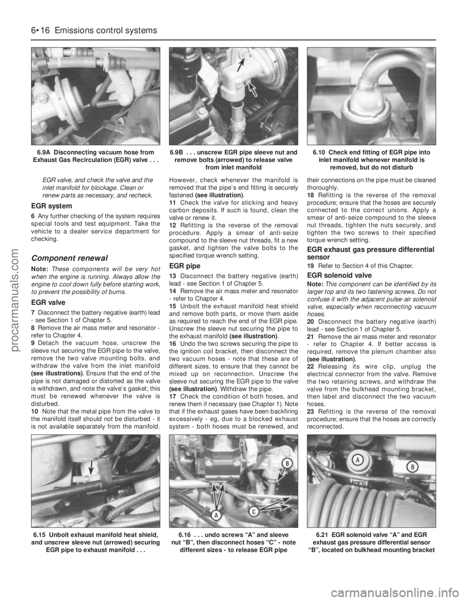
EGR valve, and check the valve and the
inlet manifold for blockage. Clean or
renew parts as necessary, and recheck.
EGR system
6Any further checking of the system requires
special tools and test equipment. Take the
vehicle to a dealer service department for
checking.
Component renewal
Note:These components will be very hot
when the engine is running. Always allow the
engine to cool down fully before starting work,
to prevent the possibility of burns.
EGR valve
7Disconnect the battery negative (earth) lead
- see Section 1 of Chapter 5.
8Remove the air mass meter and resonator -
refer to Chapter 4.
9Detach the vacuum hose, unscrew the
sleeve nut securing the EGR pipe to the valve,
remove the two valve mounting bolts, and
withdraw the valve from the inlet manifold
(see illustrations). Ensure that the end of the
pipe is not damaged or distorted as the valve
is withdrawn, and note the valve’s gasket; this
must be renewed whenever the valve is
disturbed.
10Note that the metal pipe from the valve to
the manifold itself should not be disturbed - it
is not available separately from the manifold.However, check whenever the manifold is
removed that the pipe’s end fitting is securely
fastened (see illustration).
11Check the valve for sticking and heavy
carbon deposits. If such is found, clean the
valve or renew it.
12Refitting is the reverse of the removal
procedure. Apply a smear of anti-seize
compound to the sleeve nut threads, fit a new
gasket, and tighten the valve bolts to the
specified torque wrench setting.
EGR pipe
13Disconnect the battery negative (earth)
lead - see Section 1 of Chapter 5.
14Remove the air mass meter and resonator
- refer to Chapter 4.
15Unbolt the exhaust manifold heat shield
and remove both parts, or move them aside
as required to reach the end of the EGR pipe.
Unscrew the sleeve nut securing the pipe to
the exhaust manifold (see illustration).
16Undo the two screws securing the pipe to
the ignition coil bracket, then disconnect the
two vacuum hoses - note that these are of
different sizes, to ensure that they cannot be
mixed up on reconnection. Unscrew the
sleeve nut securing the EGR pipe to the valve
(see illustration). Withdraw the pipe.
17Check the condition of both hoses, and
renew them if necessary (see Chapter 1). Note
that if the exhaust gases have been backfiring
excessively - eg, due to a blocked exhaust
system - both hoses must be renewed, andtheir connections on the pipe must be cleaned
thoroughly.
18Refitting is the reverse of the removal
procedure; ensure that the hoses are securely
connected to the correct unions. Apply a
smear of anti-seize compound to the sleeve
nut threads, tighten the nuts securely, and
tighten the two screws to their specified
torque wrench setting.
EGR exhaust gas pressure differential
sensor
19Refer to Section 4 of this Chapter.
EGR solenoid valve
Note:This component can be identified by its
larger top and its two fastening screws. Do not
confuse it with the adjacent pulse-air solenoid
valve, especially when reconnecting vacuum
hoses.
20Disconnect the battery negative (earth)
lead - see Section 1 of Chapter 5.
21Remove the air mass meter and resonator
- refer to Chapter 4. If better access is
required, remove the plenum chamber also
(see illustration).
22Releasing its wire clip, unplug the
electrical connector from the valve. Remove
the two retaining screws, and withdraw the
valve from the bulkhead mounting bracket,
then label and disconnect the two vacuum
hoses.
23Refitting is the reverse of the removal
procedure; ensure that the hoses are correctly
reconnected.
6•16 Emissions control systems
6.9A Disconnecting vacuum hose from
Exhaust Gas Recirculation (EGR) valve . . .6.9B . . . unscrew EGR pipe sleeve nut and
remove bolts (arrowed) to release valve
from inlet manifold6.10 Check end fitting of EGR pipe into
inlet manifold whenever manifold is
removed, but do not disturb
6.15 Unbolt exhaust manifold heat shield,
and unscrew sleeve nut (arrowed) securing
EGR pipe to exhaust manifold . . .6.16 . . . undo screws “A” and sleeve
nut “B”, then disconnect hoses “C” - note
different sizes - to release EGR pipe6.21 EGR solenoid valve “A” and EGR
exhaust gas pressure differential sensor
“B”, located on bulkhead mounting bracket
procarmanuals.com
Page 268 of 279
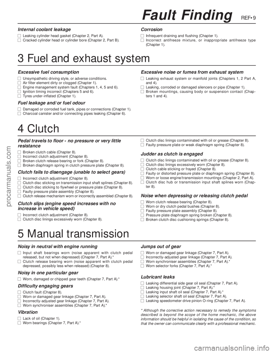
REF•9
Excessive fuel consumption
m mUnsympathetic driving style, or adverse conditions.
m mAir filter element dirty or clogged (Chapter 1).
m mEngine management system fault (Chapters 1, 4, 5 and 6).
m mIgnition timing incorrect (Chapters 5 and 6).
m mTyres under-inflated (Chapter 1).
Fuel leakage and/or fuel odour
m
mDamaged or corroded fuel tank, pipes or connections (Chapter 1).
m mCharcoal canister and/or connecting pipes leaking (Chapter 6).
Excessive noise or fumes from exhaust system
m
mLeaking exhaust system or manifold joints (Chapters 1, 2 Part A,
and 4).
m mLeaking, corroded or damaged silencers or pipe (Chapter 1).
m mBroken mountings, causing body or suspension contact (Chap-
ters 1 and 4).
Fault Finding
3 Fuel and exhaust system
Noisy in neutral with engine running
m mInput shaft bearings worn (noise apparent with clutch pedal
released, but not when depressed) (Chapter 7, Part A).*
m mClutch release bearing worn (noise apparent with clutch pedal
depressed, possibly less when released) (Chapter 8).
Noisy in one particular gear
m mWorn, damaged or chipped gear teeth (Chapter 7, Part A).*
Difficulty engaging gears
m
mClutch fault (Chapter 8).
m mWorn or damaged gear linkage (Chapter 7, Part A).
m mIncorrectly-adjusted gear linkage (Chapter 7, Part A).
m mWorn synchroniser assemblies (Chapter 7, Part A).*
Vibration
m
mLack of oil (Chapter 1).
m mWorn bearings (Chapter 7, Part A).*
Jumps out of gear
m
mWorn or damaged gear linkage (Chapter 7, Part A).
m mIncorrectly-adjusted gear linkage (Chapter 7, Part A).
m mWorn synchroniser assemblies (Chapter 7, Part A).*
m mWorn selector forks (Chapter 7, Part A).*
Lubricant leaks
m
mLeaking differential side gear oil seal (Chapter 7, Part A).
m mLeaking housing joint (Chapter 7, Part A).*
m mLeaking input shaft oil seal (Chapter 7, Part A).*
m mLeaking selector shaft oil seal (Chapter 7, Part A).
m mLeaking speedometer drive pinion O-ring (Chapter 7, Part A).
* Although the corrective action necessary to remedy the symptoms
described is beyond the scope of the home mechanic, the above
information should be helpful in isolating the cause of the condition, so
that the owner can communicate clearly with a professional mechanic.
4 Clutch
5 Manual transmission
Pedal travels to floor - no pressure or very little
resistance
m mBroken clutch cable (Chapter 8).
m mIncorrect clutch adjustment (Chapter 8).
m mBroken clutch release bearing or fork (Chapter 8).
m mBroken diaphragm spring in clutch pressure plate (Chapter 8).
Clutch fails to disengage (unable to select gears)
m
mIncorrect clutch adjustment (Chapter 8).
m mClutch disc sticking on transmission input shaft splines (Chapter 8).
m mClutch disc sticking to flywheel or pressure plate (Chapter 8).
m mFaulty pressure plate assembly (Chapter 8).
m mClutch release mechanism worn or incorrectly assembled (Chapter 8).
Clutch slips (engine speed increases with no
increase in vehicle speed)
m mIncorrect clutch adjustment (Chapter 8).
m mClutch disc linings excessively worn (Chapter 8).m mClutch disc linings contaminated with oil or grease (Chapter 8).
m mFaulty pressure plate or weak diaphragm spring (Chapter 8).
Judder as clutch is engaged
m
mClutch disc linings contaminated with oil or grease (Chapter 8).
m mClutch disc linings excessively worn (Chapter 8).
m mClutch cable sticking or frayed (Chapter 8).
m mFaulty or distorted pressure plate or diaphragm spring (Chapter 8).
m mWorn or loose engine/transmission mountings (Chapter 2, Part A).
m mClutch disc hub or transmission input shaft splines worn (Chap-
ter 8).
Noise when depressing or releasing clutch pedal
m mWorn clutch release bearing (Chapter 8).
m mWorn or dry clutch pedal bushes (Chapter 8).
m mFaulty pressure plate assembly (Chapter 8).
m mPressure plate diaphragm spring broken (Chapter 8).
m mBroken clutch disc cushioning springs (Chapter 8).
Internal coolant leakage
m
mLeaking cylinder head gasket (Chapter 2, Part A).
m mCracked cylinder head or cylinder bore (Chapter 2, Part B).
Corrosion
m
mInfrequent draining and flushing (Chapter 1).
m mIncorrect antifreeze mixture, or inappropriate antifreeze type
(Chapter 1).
procarmanuals.com