glove box cable FORD MUSTANG 1969 Volume One Chassis
[x] Cancel search | Manufacturer: FORD, Model Year: 1969, Model line: MUSTANG, Model: FORD MUSTANG 1969Pages: 413, PDF Size: 75.81 MB
Page 26 of 413
02-02-07
Brake System
02-02-07
ANTI-SKID CONTROL SYSTEM
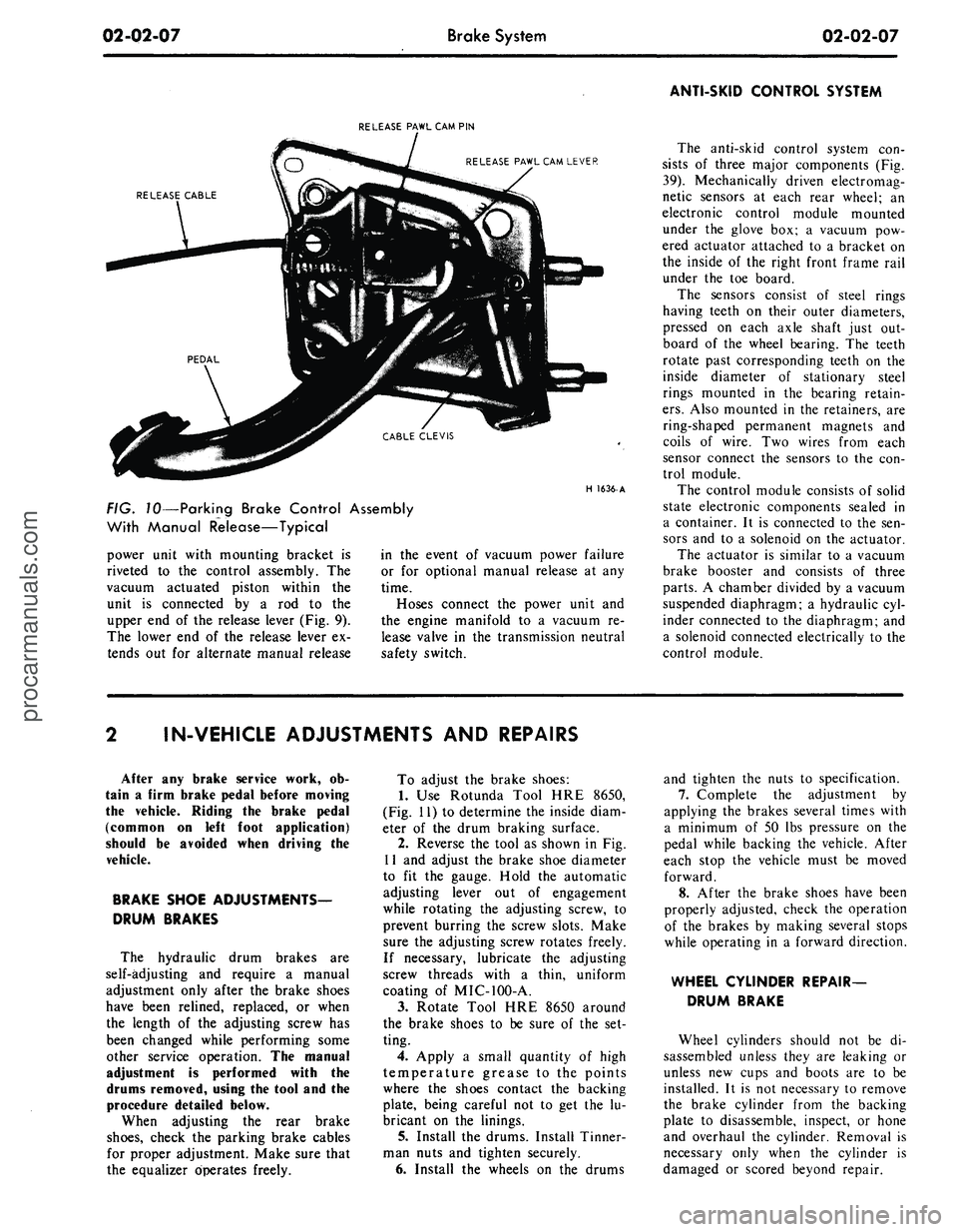
RELEASE PAWL CAM PIN
RELEASE PAWL CAM LEVER
RELEASE CABLE
H
1636-
A
FIG. 10—Parking Brake Control Assembly
With Manual Release—Typical
power unit with mounting bracket is
riveted to the control assembly. The
vacuum actuated piston within the
unit is connected by a rod to the
upper end of the release lever (Fig. 9).
The lower end of the release lever ex-
tends out for alternate manual release
in the event of vacuum power failure
or for optional manual release at any
time.
Hoses connect the power unit and
the engine manifold to a vacuum re-
lease valve in the transmission neutral
safety switch.
The anti-skid control system con-
sists of three major components (Fig.
39).
Mechanically driven electromag-
netic sensors at each rear wheel; an
electronic control module mounted
under the glove box; a vacuum pow-
ered actuator attached to a bracket on
the inside of the right front frame rail
under the toe board.
The sensors consist of steel rings
having teeth on their outer diameters,
pressed on each axle shaft just out-
board of the wheel bearing. The teeth
rotate past corresponding teeth on the
inside diameter of stationary steel
rings mounted in the bearing retain-
ers.
Also mounted in the retainers, are
ring-shaped permanent magnets and
coils of wire. Two wires from each
sensor connect the sensors to the con-
trol module.
The control module consists of solid
state electronic components sealed in
a container. It is connected to the sen-
sors and to a solenoid on the actuator.
The actuator is similar to a vacuum
brake booster and consists of three
parts.
A chamber divided by a vacuum
suspended diaphragm; a hydraulic cyl-
inder connected to the diaphragm; and
a solenoid connected electrically to the
control module.
IN-VEHICLE ADJUSTMENTS AND REPAIRS
After any brake service work, ob-
tain a firm brake pedal before moving
the vehicle. Riding the brake pedal
(common on left foot application)
should be avoided when driving the
vehicle.
BRAKE SHOE ADJUSTMENTS—
DRUM BRAKES
The hydraulic drum brakes are
self-adjusting and require a manual
adjustment only after the brake shoes
have been relined, replaced, or when
the length of the adjusting screw has
been changed while performing some
other service operation. The manual
adjustment is performed with the
drums removed, using the tool and the
procedure detailed below.
When adjusting the rear brake
shoes,
check the parking brake cables
for proper adjustment. Make sure that
the equalizer operates freely.
To adjust the brake shoes:
1.
Use Rotunda Tool HRE 8650,
(Fig. 11) to determine the inside diam-
eter of the drum braking surface.
2.
Reverse the tool as shown in Fig.
11 and adjust the brake shoe diameter
to fit the gauge. Hold the automatic
adjusting lever out of engagement
while rotating the adjusting screw, to
prevent burring the screw slots. Make
sure the adjusting screw rotates freely.
If necessary, lubricate the adjusting
screw threads with a thin, uniform
coating of MIC-100-A.
3.
Rotate Tool HRE 8650 around
the brake shoes to be sure of the set-
ting.
4.
Apply a small quantity of high
temperature grease to the points
where the shoes contact the backing
plate, being careful not to get the lu-
bricant on the linings.
5. Install the drums. Install Tinner-
man nuts and tighten securely.
6. Install the wheels on the drums
and tighten the nuts to specification.
7.
Complete the adjustment by
applying the brakes several times with
a minimum of 50 lbs pressure on the
pedal while backing the vehicle. After
each stop the vehicle must be moved
forward.
8. After the brake shoes have been
properly adjusted, check the operation
of the brakes by making several stops
while operating in a forward direction.
WHEEL CYLINDER REPAIR-
DRUM BRAKE
Wheel cylinders should not be di-
sassembled unless they are leaking or
unless new cups and boots are to be
installed. It is not necessary to remove
the brake cylinder from the backing
plate to disassemble, inspect, or hone
and overhaul the cylinder. Removal is
necessary only when the cylinder is
damaged or scored beyond repair.procarmanuals.com
Page 55 of 413
02-02-36
Brake System
02-02-36
locating stripe on the cable is midway
between the retaining clips and tighten
all retaining clip screws.
4.
Position the left cable, retaining
clip and screw on the left lower sus-
pension arm. Compress the prongs on
the left cable and position the cable
through the frame side-member. The
prongs must be securely locked in
place.
5.
Insert the ball ends of the cables
into the equalizer assembly.
6. Install the rear drum(s) and
tighten the three Tinnerman nuts and
secure the drum. Install the wheel and
tire and the wheel cover.
7.
Adjust the parking brake linkage
as outlined in Part 2-1, Section 2. Ad-
just the rear brakes, as required (Part
2-1,
Section 2).
FAIRLANE, MONTEGO,
MUSTANG AND COUGAR—
EXCEPT STATION WAGON
Removal
1.
Remove the equalizer lock nut
and adjusting nut, equalizer, spring
and spring seat.
2.
With the cables slack, discon-
nect the ball-ends from the connector
(Figs.
35 and 36).
3.
Remove the cable from the re-
tainer hooks (station wagon models)
and the underbody guide (convertible
models) if required.
4.
Remove the hairpin lock retain-
ing the cable housing to the side rail
bracket.
5.
Remove the wheel cover, wheel
and tire and the rear brake drum as
outlined in Section 2.
6. Remove self-adjuster springs to
allow clearance to remove cable re-
tainer from the backing plate. Discon-
nect the rear end of the cable from the
parking brake lever on the brake shoe.
Disengage the cable housing retaining
grommet or steel-pronged Hi-Hat
from the backing plate and withdraw
the cable and housing from the in-
board side of the backing plate.
7.
Slide the cable and housing out
of the side rail bracket.
Installation
1.
Insert the rear end of the cable
through the side rail bracket and pull
the cable and housing into position.
2.
Insert the rear end of the cable
and housing through the hole in the
backing plate from the inboard side.
3.
Connect the cable to the parking
brake lever on the brake shoe and in-
stall the cable housing retaining grom-
met or steel-pronged Hi-Hat in the
backing plate.
4.
Install the self-adjuster springs.
Position the cable housing in the side
rail bracket and install the hairpin
type retainer.
5.
Install rear hub and drum as-
sembly, wheel and tire assemblies and
wheel cover as outlined in Section 2.
6. Position the cable retainer hooks
(station wagon models) in the under-
body guide (convertible models) and
install the connector, thus hooking the
two cables together.
7.
Insert the cable into the equaliz-
er and install the equalizer, spring
seat, spring, adjusting nut and lock
nut to the front, parking brake control
cable.
8. Adjust the parking brake^as di-
rected in Part 2-1, Section 2.
FAIRLANE AND MONTEGO
STATION WAGONS AND
FALCON PASSENGER
MODELS
Removal and Installation
Refer to Fig. 35.
Generally follow the procedure
given above, omitting separation of
the cables, since the parking brake
rear cable assemblies supplied for
these models is in one piece. Removal
and installation of both rear wheels,
tires and drums will also be required.
LINCOLN CONTINENTAL
Removal
1.
Raise the car. Remove the rear
wheel cover. Remove the wheel and
tire as an assembly.
2.
Remove the three Tinnerman
nuts that hold the brake drum in
place, and remove the drum.
3.
Remove the brake shoe retract-
ing springs.
4.
Loosen the equalizer rod adjust-
ing nut and disconnect the cable from
the equalizer (Fig. 38).
5.
Remove the hairpin-type retainer
clip that secures the cable housing to
the body bracket, and pull the cable
and housing out of the bracket (Fig.
38).
6. Remove the cable to underbody
clamp attaching nuts and the clamp.
Disengage the cable housing from the
hook-type retainer at the spring U-
bolt.
7.
Working on the wheel side of the
backing plate (Fig. 38), compress the
prongs on the cable retainer so that it
can pass through the hole in the back-
ing plate. Draw the cable retainer out
of the hole.
8. With the spring tension off the
parking brake lever, lift the cable out
of the slot in the lever and remove it
through the backing plate hols.
Installation
1.
Pull enough of the cable through
the cable housing so that the end of
the cable may be inserted through the
backing plate hole from the inner side
and engage the cable end with the slot
in the parking brake lever.
2.
Pull the excess slack from the
cable and insert the cable housing into
the backing plate access hole (Fig.
38).
The prongs must be securely
locked in place.
3.
Install the brake shoe retracting
springs.
4.
Position the cable to the under-
body and install the retaining clamp
so that the cable conduit armor ex-
tends forward of the clamp as shown
in Fig. 38. Install the clamp retaining
nuts.
5.
Hook the cable housing to the
retainer at the spring U-bolt.
6. Engage the forward end of the
cable housing with the frame bracket
and secure it with the hairpin-type
clip.
7.
Insert the ball end of the cable
into the equalizer.
8. Make a preliminary brake ad-
justment with the use of Tool HRA-
8650 (Fig. 11).
9. Install the rear drum. Tighten
the three Tinnerman nuts that secure
the drum. Install the wheel and wheel
cover.
10.
Adjust the parking brake link-
age.
11.
Lower the vehicle.
ANTI-SKID CONTROL
ACTUATOR
REMOVAL
Refer to Fig. 39.
1.
Working in the passenger com-
partment, under the glove box, remove
the screw that attaches the forward
end of the control module retainer to
the support assembly. Lower the for-
ward end of the control module re-
tainer and remove the module assem-
bly.procarmanuals.com