heat FORD MUSTANG 1969 Volume One Chassis
[x] Cancel search | Manufacturer: FORD, Model Year: 1969, Model line: MUSTANG, Model: FORD MUSTANG 1969Pages: 413, PDF Size: 75.81 MB
Page 19 of 413
02-01-08
Brakes
02-01-08
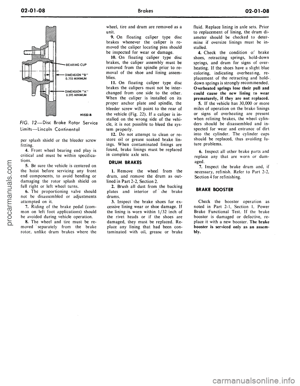
BEARING CUP
DIMENSION "B"
0.755 MINIMUM
DIMENSION "A'
0.395 MINIMUM
H1532-B
FIG. 12—Disc Brake Rotor Service
Limits—Lincoln Continental
per splash shield or the bleeder screw
fitting.
4.
Front wheel bearing end play is
critical and must be within specifica-
tions.
5.
Be sure the vehicle is centered on
the hoist before servicing any front
end components, to avoid bending or
damaging the rotor splash shield on
full right or left wheel turns.
6. The proportioning valve should
not be disassembled or adjustments
attempted on it.
7.
Riding of the brake pedal (com-
mon on left foot applications) should
be avoided during vehicle operation.
8. The wheel and tire must be re-
moved ' separately from the brake
rotor, unlike drum brakes where the
wheel, tire and drum are removed as a
unit.
9. On floating caliper type disc
brakes whenever the caliper is re-
moved the caliper locating pins should
be inspected for wear or damage.
10.
On floating caliper type disc
brakes, the caliper assembly must be
removed from the spindle prior to re-
moval of the shoe and lining assem-
blies.
11.
On floating caliper type disc
brakes the calipers must not be inter-
changed from one side to the other.
When the caliper is installed on its
proper anchor plate and spindle, the
bleeder screw will point to the rear of
the vehicle (Fig. 22). If a caliper is in-
stalled on the wrong side of the vehi-
cle,
it is not possible to bleed the sys-
tem properly.
12.
Do not attempt to clean or re-
store oil or grease soaked brake lin-
ings.
When contaminated linings are
found, brake linings must be replaced
in complete axle sets.
DRUM BRAKES
1.
Remove the wheel from the
drum, and remove the drum as out-
lined in Part 2-2, Section 2.
2.
Brush all dust from the backing
plates and interior of the brake
drums.
3.
Inspect the brake shoes for ex-
cessive lining wear or shoe damage. If
the lining is worn within 1/32 inch of
the rivet heads or if the shoes are
damaged, they must be replaced. Re-
place any lining that had been con-
taminated with oil, grease or brake
fluid. Replace lining in axle sets. Prior
to replacement of lining, the drum di-
ameter should be checked to deter-
mine if oversize linings must be in-
stalled.
4.
Check the condition of brake
shoes,
retracting springs, hold-down
springs, and drum for signs of over-
heating. If the shoes have a slight blue
coloring, indicating overheating, re-
placement of the retracting and hold-.
down springs is strongly recommended.
Overheated springs lose their pull and
could cause the new lining i:o wear
prematurely, if they are not replaced.
5. If the vehicle has 30,000 or more
miles of operation on the brake linings
or signs of overheating are present
when relining brakes, the wheel cylin-
ders should be disassembled and in-
spected for wear and entrance of dirt
into the cylinder. The cylinder cups
should be replaced, thus avoiding fu-
ture problems.
6. Inspect all other brake parts and
replace any that are worn or dam-
aged.
7.
Inspect the brake drum and, if
necessary, refinish. Refer to Part 2-2,
Section 4 for refinishing.
BRAKE BOOSTER
Check the booster operation as
noted in Part 2-1, Section 1, Power
Brake Functional Test. If the brake
booster is damaged or defective, re-
place it with a new booster. The brake
booster is serviced only as an assem-
bly.procarmanuals.com
Page 46 of 413
02-02-27
Brake System
02-02-27
4.
Connect the stop light switch
wires to the connector, and install the
wires in the retaining clip.
5.
Torque the booster mounting
nuts to specifications.
LINCOLN CONTINENTAL
Removal
1.
Disconnect the battery ground
cable from the battery.
2.
It is necessary to obtain clear-
ance to remove vacuum hoses and the
electrical connector to the temperature
heat control box. Remove the two
screws retaining the relay to the fend-
er and push the relay aside. Discon-
nect the vacuum hoses and connector
at the heat control box.
3.
Working under the instrument
panel, disconnect the vacuum hoses,
wires and retaining clip from the tem-
perature heat control box. Remove the
two screws securing the temperature
control box to the dash panel.
4.
Remove the lower control hous-
ing retaining screws (6). Disconnect
the wire harnesses at the lower control
panel and place the panel aside. Re-
move the wire harness shield. Remove
the wire harness clip. Position the
wire harness aside. Remove the tem-
perature control box and position it
aside.
5.
Remove the hair-pin type retain-
er. Slide the stop light switch off the
brake pedal pin just far enough for
the switch outer hole to clear the pin.
Lift the switch upward from the pin.
Slide the master cylinder push rod,
nylon washers and bushing off the
brake pedal pin.
6. Remove the pivot bolt and nut
that holds the pedal to the pedal sup-
port bracket. Remove the brake pedal
assembly from the support bracket
and remove the bushings.
7.
If required, remove the brake
pedal pad retaining nuts and remove
the brake pedal pad.
Installation
1.
If the brake pedal pad was re-
moved, position the pad on the pedal.
Install the pad retaining nuts and tor-
que them to specification.
2.
Apply SAE 10 engine oil to the
bushings and locate all the bushings in
their proper places on the pedal as-
sembly.
3.
Install the brake pedal assembly
and bushings to the support bracket,
and then install the pivot bolt through
the support bracket and pedal assem-
bly. Install the pivot bolt nut and tor-
que it to specification.
4.
Install the inner nylon washer,the
master cylinder push rod link, and the
bushing on the brake pedal pin. Posi-
tion the switch so that it straddles the
push rod link with the switch slot on
the pedal and the switch outer hole
just clearing the pin. Install the outer
nylon washer as shown in Fig. 33. In-
stall the hair-pin type retainer on the
brake pedal pin.
5.
Connect the stop light switch
wires to the connector, and install the
wires in the retaining clip.
6. Position the wire harness and
clip on the temperature control box
and install the retaining screw. Posi-
tion the temperature control box to
the dash panel and install the two re-
taining bolts.
7.
Connect the vacuum lines and
the electrical connector to the control
box. Position the wire harness to the
control box and install the retaining
clip.
8. Position the wire harness shield
and install two retaining bolts.
9. Connect the wire harnesses to
the lower control panel and install the
retaining screws.
10.
Working within the engine
compartment, connect the wire con-
nector to the temperature heat control
box.
11.
Position the relay to the fender
apron and install the retaining bolts.
12.
Connect the ground cable to the
battery.
13.
Check the brakes and light
switch for proper operation. Close the
hood.
PARKING BRAKE CONTROL
ASSEMBLY
FORD, MERCURY
AND METEOR
Removal
Refer to Fig. 34.
1.
Make sure the parking brake is
fully released.
2.
Remove all tension from the rear
cables by backing off the adjusting nut
from the equalizer.
3.
Remove the roll pin that secures
the release knob to the cable and re-
move the knob.
4.
Remove the nut that secures the
release cable to the instrument panel
and remove the cable from the rear of
the instrument panel.
5.
Remove the two nuts attaching
the control assembly to the dash
panel.
6. Remove the cap screw attaching
the control assembly to the cowl side
bracket.
7.
Disconnect the hose to the park-
ing brake vacuum unit, if so equipped.
8. Remove the front cable assembly
retainer clip from the cable assembly
and disconnect the cable ball from the
control clevis.
9. Remove the control assembly
from the vehicle.
Installation
1.
Position the control assembly in
the vehicle.
2.
Fit the cable assembly through
its mounting hole and install the re-
taining clip. Connect the cable ball to
the control clevis.
3.
Connect the vacuum hose to the
parking brake unit, if so equipped.
4.
Install the attaching cap screw to
the cowl side bracket. Do not tighten.
5.
Install the two control assemb-
ly-to-dash panel nuts. Tighten the nuts
and the cap screw to specifications.
6. Insert the release cable into the
instrument panel and install the re-
taining nut.
7.
Install the release knob on the
cable with the roll pin.
8. Check the operation of the park-
ing brake. Adjust the parking brake
as required.
FAIRLANE, MONTEGO
AND FALCON
Removal
Refer to Fig. 35.
1.
Make sure the parking brake is
completely released.
2.
Remove all tension from the rear
cables by backing off the jam nut and
adjusting nut from the equalizer.
3.
Working inside the vehicle, re-
move the four bolts and one nut re-
taining the left air vent and cable as-
sembly to the dash and instrument
panels. Remove the vent assembly.
4.
Remove the parking brake front
cable ball retaining clip from the clev-
is.
5.
Disconnect the cable ball from
the notch in the brake clevis.
6. Remove the three screws that at-
tach the control assembly to the left
cowl inner side panel.procarmanuals.com
Page 251 of 413
05-01-04
Drive Shaft
05-01-04
tralizing.
If a
vibration exists,
the
drive shaft should
be
disconnected
from
the
axle, rotated 180 degrees
and
reinstalled.
3.
Install
the
U-blots
and
nuts that
attach
the
U-joint
to the
drive pinion
flange. Torque
the
U-bolt nuts
to
specification.
On
vehicles equipped
with
a
double cardan joint, install
the
rear joint-to-drive pinion flange
at-
taching bolts. Torque
the
bolts
to spe-
cification.
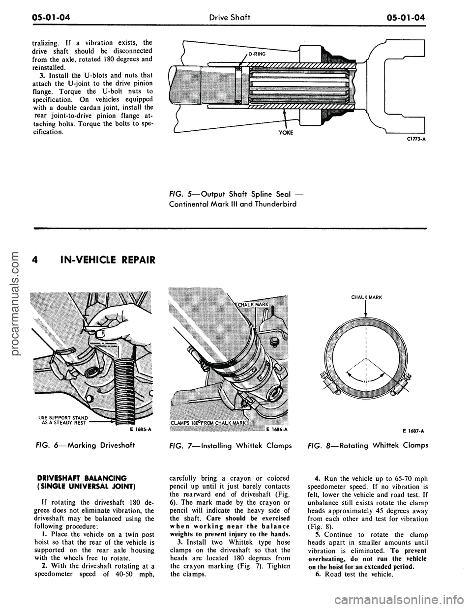
YOKE
C1773-A
FIG. 5—Output Shaft Spline Seal
—
Continental Mark
III
and Thunderbird
IN-VEHICLE REPAIR
USE SUPPORT STAND
AS
A
STEADY REST
E 1685-A
FIG. 6—Marking Driveshaft
CHALK MARK
CLAMPS 18d*FR0M CHALK MARK
*« >
E 1686-A
FIG. 7—Installing Whittek Clamps
E
1687-
A
. 8—Rotating Whittek Clamps
DRIVESHAFT BALANCING
(SINGLE UNIVERSAL JOINT)
If rotating
the
driveshaft
180 de-
grees does
not
eliminate vibration,
the
driveshaft
may be
balanced using
the
following procedure:
1.
Place
the
vehicle
on a
twin post
hoist
so
that
the
rear
of the
vehicle
is
supported
on the
rear axle housing
with
the
wheels free
to
rotate.
2.
With
the
driveshaft rotating
at a
speedometer speed
of
40-50
mph,
carefully bring
a
crayon
or
colored
pencil
up
until
it
just barely contacts
the rearward
end of
driveshaft
(Fig.
6).
The
mark made
by the
crayon
or
pencil will indicate
the
heavy side
of
the shaft. Care should
be
exercised
when working near
the
balance
weights
to
prevent injury
to the
hands.
3.
Install
two
Whittek type hose
clamps
on the
driveshaft
so
that
the
heads
are
located
180
degrees from
the crayon marking
(Fig. 7).
Tighten
the clamps.
4.
Run the
vehicle
up to
65-70
mph
speedometer speed.
If no
vibration
is
felt, lower
the
vehicle
and
road test.
If
unbalance still exists rotate
the
clamp
heads approximately
45
degrees away
from each other
and
test
for
vibration
(Fig.
8).
5.
Continue
to
rotate
the
clamp
heads apart
in
smaller amounts until
vibration
is
eliminated.
To
prevent
overheating,
do not run the
vehicle
on
the
hoist
for an
extended period.
6. Road test
the
vehicle.procarmanuals.com
Page 258 of 413
05-02-04
General Clutch Service
05-02-04
CLEANING AND INSPECTION
RELEASE BEARING
Wipe all oil and dirt off the release
bearing. The bearing is prelubricated
and should not be cleaned with sol-
vent.
Inspect the bearing retainer for
loose spring clips and rivets.
Inspect the release bearing assembly
for burrs which may cause the assem-
bly to drag on the transmission bear-
ing retainer. Any such burrs should be
cleaned up with fine crocus cloth. If
burrs are found, inspect the transmis-
sion input shaft bearing retainer for
evidence of scoring. Any scoring
should be polished out with crocus
cloth. Coat the bearing retainer with a
thin film of lithium-base grease
(C3VY-19586-A). Prior to release
bearing installation, apply a light film
of lithium base grease (C3VY-
19586-A) on both sides of the release
lever fork where it contacts the release
bearing hub and retaining springs.
Apply a light film of lithium base
grease (C3VY-19586-A) plate to the
release bearing surface that contacts
the pressure plate fingers. Carefully
fill the grease groove inside the bear-
ing hub with lithium base grease (no
polyethylene). Clean all excess grease
from the bore of the bearing hub. Ex-
cess grease will be forced onto the
spline by the transmission input shaft
bearing retainer and will contaminate
the clutch disc. Also, care must be
exercised when applying lubricants to
the release bearing, release bearing
hub and the release lever fork to avoid
excessive grease from contaminating
the clutch disc.
Hold the bearing inner race and ro-
tate the outer race while applying
pressure to it. If the bearing rotation
is rough or noisy, replace the bearing.
Most release bearing failures are
caused by improper clutch pedal ad-
justments. If the clutch linkage does
not have enough free travel, the re-
lease bearing will constantly touch the
release fingers and will spin whenever
the engine is running.
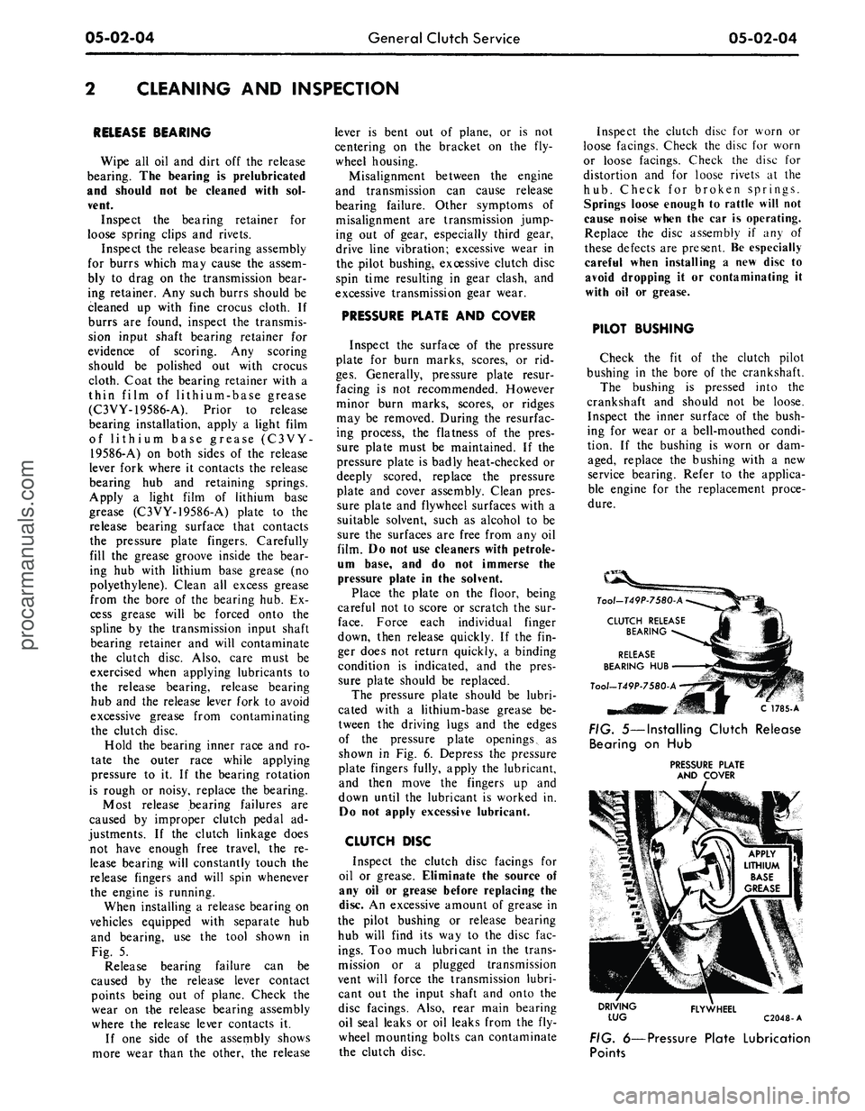
When installing a release bearing on
vehicles equipped with separate hub
and bearing, use the tool shown in
Fig. 5.
Release bearing failure can be
caused by the release lever contact
points being out of plane. Check the
wear on the release bearing assembly
where the release lever contacts it.
If one side of the assembly shows
more wear than the other, the release
lever is bent out of plane, or is not
centering on the bracket on the fly-
wheel housing.
Misalignment between the engine
and transmission can cause release
bearing failure. Other symptoms of
misalignment are transmission jump-
ing out of gear, especially third gear,
drive line vibration; excessive wear in
the pilot bushing, excessive clutch disc
spin time resulting in gear clash, and
excessive transmission gear wear.
PRESSURE PLATE AND COVER
Inspect the surface of the pressure
plate for burn marks, scores, or rid-
ges.
Generally, pressure plate resur-
facing is not recommended. However
minor burn marks, scores, or ridges
may be removed. During the resurfac-
ing process, the flatness of the pres-
sure plate must be maintained. If the
pressure plate is badly heat-checked or
deeply scored, replace the pressure
plate and cover assembly. Clean pres-
sure plate and flywheel surfaces with a
suitable solvent, such as alcohol to be
sure the surfaces are free from any oil
film. Do not use cleaners with petrole-
um base, and do not immerse the
pressure plate in the solvent.
Place the plate on the floor, being
careful not to score or scratch the sur-
face.
Force each individual finger
down, then release quickly. If the fin-
ger does not return quickly, a binding
condition is indicated, and the pres-
sure plate should be replaced.
The pressure plate should be lubri-
cated with a lithium-base grease be-
tween the driving lugs and the edges
of the pressure plate openings, as
shown in Fig. 6. Depress the pressure
plate fingers fully, apply the lubricant,
and then move the fingers up and
down until the lubricant is worked in.
Do not apply excessive lubricant.
CLUTCH DISC
Inspect the clutch disc facings for
oil or grease. Eliminate the source of
any oil or grease before replacing the
disc. An excessive amount of grease in
the pilot bushing or release bearing
hub will find its way to the disc fac-
ings.
Too much lubricant in the trans-
mission or a plugged transmission
vent will force the transmission lubri-
cant out the input shaft and onto the
disc facings. Also, rear main bearing
oil seal leaks or oil leaks from the fly-
wheel mounting bolts can contaminate
the clutch disc.
Inspect the clutch disc for worn or
loose facings. Check the disc for worn
or loose facings. Check the disc for
distortion and for loose rivets at the
hub.
Check for broken springs.
Springs loose enough to rattle will not
cause noise when the car is operating.
Replace the disc assembly if any of
these defects are present. Be especially
careful when installing a new disc to
avoid dropping it or contaminating it
with oil or grease.
PILOT BUSHING
Check the fit of the clutch pilot
bushing in the bore of the crankshaft.
The bushing is pressed into the
crankshaft and should not be loose.
Inspect the inner surface of the bush-
ing for wear or a bell-mouthed condi-
tion. If the bushing is worn or dam-
aged, replace the bushing with a new
service bearing. Refer to the applica-
ble engine for the replacement proce-
dure.
C 1785-A
FIG. 5—Installing Clutch Release
Bearing on Hub
PRESSURE PLATE
AND COVER
DRIVING
LUG
FLYWHEEL
C2048-A
FIG. 6—Pressure Plate Lubrication
Pointsprocarmanuals.com