relay FORD MUSTANG 2003 4.G Owners Manual
[x] Cancel search | Manufacturer: FORD, Model Year: 2003, Model line: MUSTANG, Model: FORD MUSTANG 2003 4.GPages: 256, PDF Size: 2.4 MB
Page 2 of 256
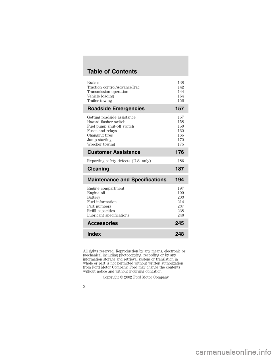
Brakes 138
Traction control/AdvanceTrac 142
Transmission operation 144
Vehicle loading 154
Trailer towing 156
Roadside Emergencies 157
Getting roadside assistance 157
Hazard flasher switch 158
Fuel pump shut-off switch 159
Fuses and relays 160
Changing tires 165
Jump starting 170
Wrecker towing 175
Customer Assistance 176
Reporting safety defects (U.S. only) 186
Cleaning 187
Maintenance and Specifications 194
Engine compartment 197
Engine oil 199
Battery 203
Fuel information 214
Part numbers 237
Refill capacities 238
Lubricant specifications 240
Accessories 245
Index 248
All rights reserved. Reproduction by any means, electronic or
mechanical including photocopying, recording or by any
information storage and retrieval system or translation in
whole or part is not permitted without written authorization
from Ford Motor Company. Ford may change the contents
without notice and without incurring obligation.
Copyright © 2002 Ford Motor Company
Table of Contents
2
Page 145 of 256
3. Start the vehicle.
If it is necessary to use the above procedure to
move the gearshift lever, it is possible that a fuse
has blown or the vehicle’s brakelamps are not
operating properly. Refer toFuses and relaysin the
Roadside emergencieschapter.
Do not drive your vehicle until you verify
that the brakelamps are working.
If your vehicle gets stuck in mud or snow it may be
rocked out by shifting from forward and reverse
gears, stopping between shifts, in a steady pattern.
Press lightly on the accelerator in each gear.
Do not rock the vehicle if the engine is not at
normal operating temperature or damage to
the transmission may occur.
Do not rock the vehicle for more than a few
minutes or damage to the transmission and
tires may occur or the engine may overheat.
Always set the parking brake fully and make
sure the gearshift is latched in P (Park).
Turn the ignition to the LOCK position and remove
the key whenever you leave your vehicle.
If the parking brake is fully released, but the
brake warning lamp remains illuminated, the
brakes may not be working properly. See your
dealer or a qualified service technician.
Driving
145
Page 160 of 256
FUSES AND RELAYS
Fuses
If electrical
components in the
vehicle are not
working, a fuse may
have blown. Blown
fuses are identified by a broken wire within the fuse.
Check the appropriate fuses before replacing any
electrical components.
Note:Always replace a fuse with one that has the
specified amperage rating. Using a fuse with a higher
amperage rating can cause severe wire damage and
could start a fire.
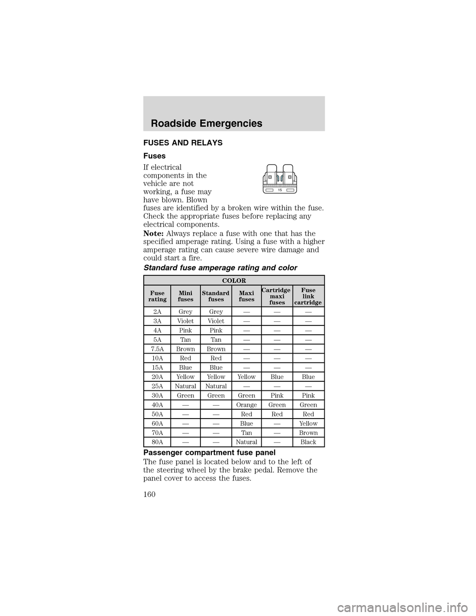
Standard fuse amperage rating and color
COLOR
Fuse
ratingMini
fusesStandard
fusesMaxi
fusesCartridge
maxi
fusesFuse
link
cartridge
2A Grey Grey—— —
3A Violet Violet—— —
4A Pink Pink—— —
5A Tan Tan—— —
7.5A Brown Brown—— —
10A Red Red—— —
15A Blue Blue—— —
20A Yellow Yellow Yellow Blue Blue
25A Natural Natural—— —
30A Green Green Green Pink Pink
40A——Orange Green Green
50A——Red Red Red
60A——Blue—Yellow
70A——Ta n—Brown
80A——Natural—Black
Passenger compartment fuse panel
The fuse panel is located below and to the left of
the steering wheel by the brake pedal. Remove the
panel cover to access the fuses.
15
Roadside Emergencies
160
Page 161 of 256
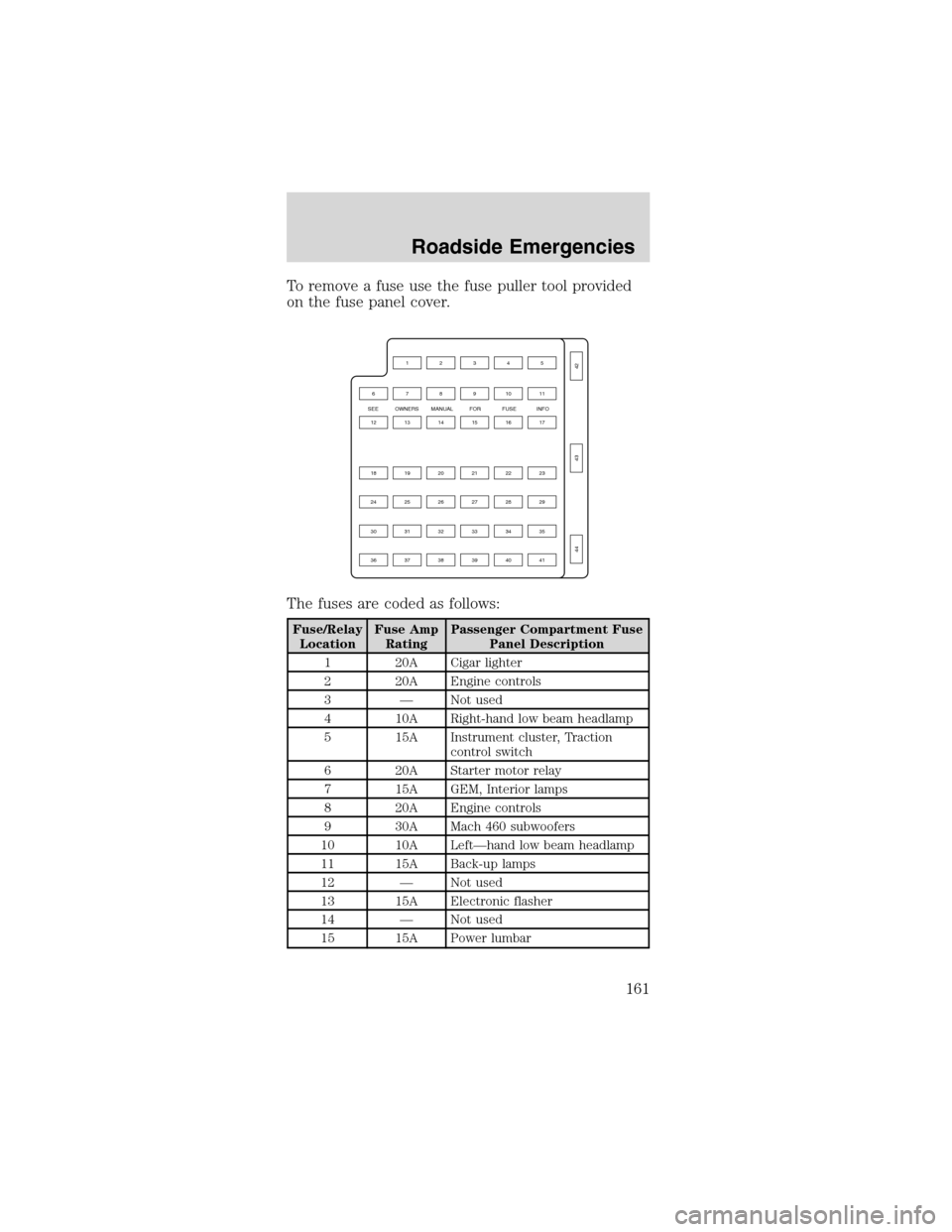
To remove a fuse use the fuse puller tool provided
on the fuse panel cover.
The fuses are coded as follows:
Fuse/Relay
LocationFuse Amp
RatingPassenger Compartment Fuse
Panel Description
1 20A Cigar lighter
2 20A Engine controls
3—Not used
4 10A Right-hand low beam headlamp
5 15A Instrument cluster, Traction
control switch
6 20A Starter motor relay
7 15A GEM, Interior lamps
8 20A Engine controls
9 30A Mach 460 subwoofers
10 10A Left—hand low beam headlamp
11 15A Back-up lamps
12—Not used
13 15A Electronic flasher
14—Not used
15 15A Power lumbar
SEE OWNERS MANUAL FOR FUSE INFO
4212345
76891011
131214151617
191820212223
252426272829
313032333435
373638394041
43
44
Roadside Emergencies
161
Page 162 of 256
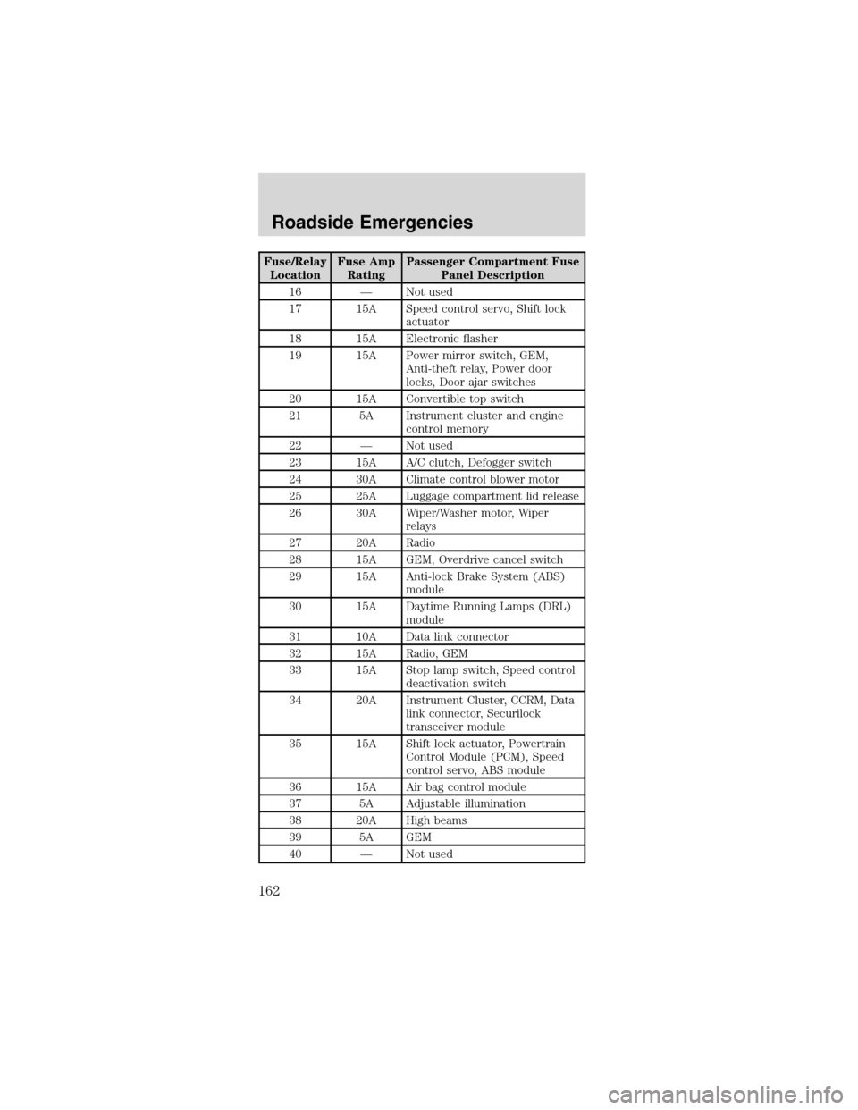
Fuse/Relay
LocationFuse Amp
RatingPassenger Compartment Fuse
Panel Description
16—Not used
17 15A Speed control servo, Shift lock
actuator
18 15A Electronic flasher
19 15A Power mirror switch, GEM,
Anti-theft relay, Power door
locks, Door ajar switches
20 15A Convertible top switch
21 5A Instrument cluster and engine
control memory
22—Not used
23 15A A/C clutch, Defogger switch
24 30A Climate control blower motor
25 25A Luggage compartment lid release
26 30A Wiper/Washer motor, Wiper
relays
27 20A Radio
28 15A GEM, Overdrive cancel switch
29 15A Anti-lock Brake System (ABS)
module
30 15A Daytime Running Lamps (DRL)
module
31 10A Data link connector
32 15A Radio, GEM
33 15A Stop lamp switch, Speed control
deactivation switch
34 20A Instrument Cluster, CCRM, Data
link connector, Securilock
transceiver module
35 15A Shift lock actuator, Powertrain
Control Module (PCM), Speed
control servo, ABS module
36 15A Air bag control module
37 5A Adjustable illumination
38 20A High beams
39 5A GEM
40—Not used
Roadside Emergencies
162
Page 163 of 256
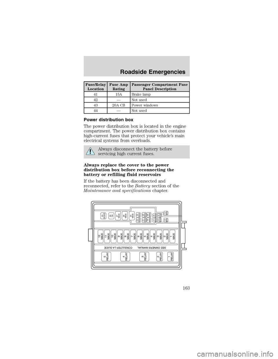
Fuse/Relay
LocationFuse Amp
RatingPassenger Compartment Fuse
Panel Description
41 15A Brake lamp
42—Not used
43 20A CB Power windows
44—Not used
Power distribution box
The power distribution box is located in the engine
compartment. The power distribution box contains
high-current fuses that protect your vehicle’s main
electrical systems from overloads.
Always disconnect the battery before
servicing high current fuses.
Always replace the cover to the power
distribution box before reconnecting the
battery or refilling fluid reservoirs
If the battery has been disconnected and
reconnected, refer to theBatterysection of the
Maintenance and specificationschapter.
5
RELAY4
RELAY3
RELAY2
RELAY1
RELAY
12
MAXI
29
DIODE28
CB27
MAXI26
MAXI25
MAXI23
MINI
24
MINI
21
MINI
22
MINI
19
MINI17
MINI18
MINI15
MINI13
MINI
14
MINI16
MINI20
MINI
11
MAXI10
MAXI9
MAXI8
MAXI7
MAXI6
MAXI5
MAXI4
MAXI3
MAXI2
MAXI1
MAXI
SEE OWNERS MANUAL CONSULTER LA GUIDE
Roadside Emergencies
163
Page 164 of 256
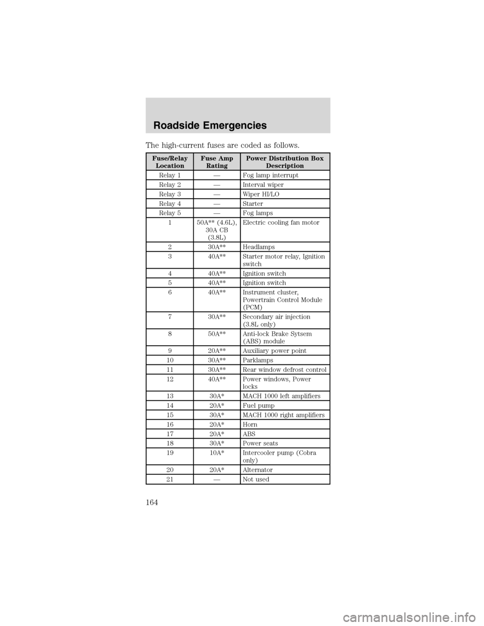
The high-current fuses are coded as follows.
Fuse/Relay
LocationFuse Amp
RatingPower Distribution Box
Description
Relay 1—Fog lamp interrupt
Relay 2—Interval wiper
Relay 3—Wiper HI/LO
Relay 4—Starter
Relay 5—Fog lamps
1 50A** (4.6L),
30A CB
(3.8L)Electric cooling fan motor
2 30A** Headlamps
3 40A** Starter motor relay, Ignition
switch
4 40A** Ignition switch
5 40A** Ignition switch
6 40A** Instrument cluster,
Powertrain Control Module
(PCM)
7 30A** Secondary air injection
(3.8L only)
8 50A** Anti-lock Brake Sytsem
(ABS) module
9 20A** Auxiliary power point
10 30A** Parklamps
11 30A** Rear window defrost control
12 40A** Power windows, Power
locks
13 30A* MACH 1000 left amplifiers
14 20A* Fuel pump
15 30A* MACH 1000 right amplifiers
16 20A* Horn
17 20A* ABS
18 30A* Power seats
19 10A* Intercooler pump (Cobra
only)
20 20A* Alternator
21—Not used
Roadside Emergencies
164
Page 165 of 256
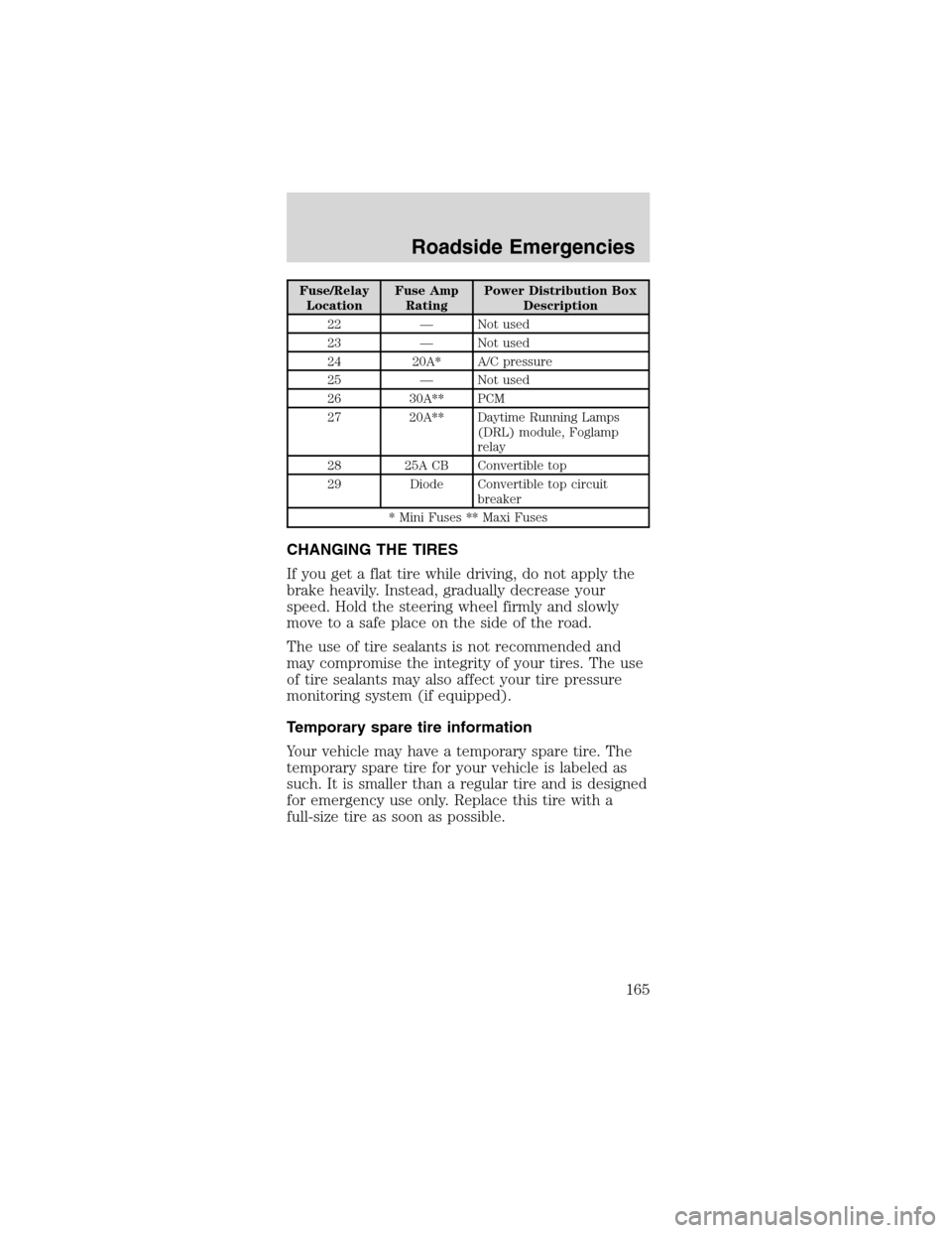
Fuse/Relay
LocationFuse Amp
RatingPower Distribution Box
Description
22—Not used
23—Not used
24 20A* A/C pressure
25—Not used
26 30A** PCM
27 20A** Daytime Running Lamps
(DRL) module, Foglamp
relay
28 25A CB Convertible top
29 Diode Convertible top circuit
breaker
* Mini Fuses ** Maxi Fuses
CHANGING THE TIRES
If you get a flat tire while driving, do not apply the
brake heavily. Instead, gradually decrease your
speed. Hold the steering wheel firmly and slowly
move to a safe place on the side of the road.
The use of tire sealants is not recommended and
may compromise the integrity of your tires. The use
of tire sealants may also affect your tire pressure
monitoring system (if equipped).
Temporary spare tire information
Your vehicle may have a temporary spare tire. The
temporary spare tire for your vehicle is labeled as
such. It is smaller than a regular tire and is designed
for emergency use only. Replace this tire with a
full-size tire as soon as possible.
Roadside Emergencies
165
Page 253 of 256
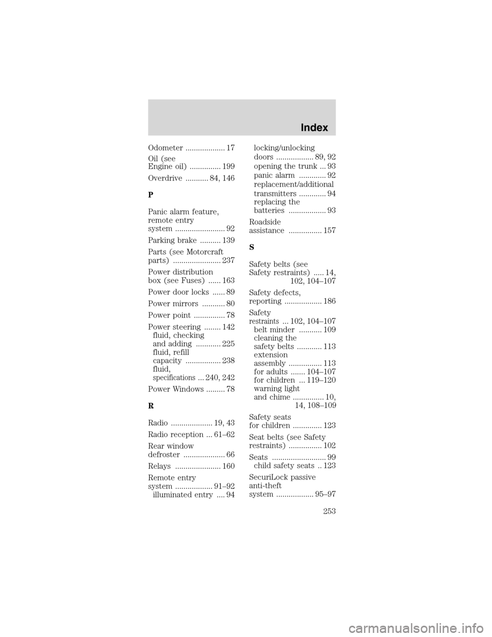
Odometer ................... 17
Oil (see
Engine oil) ............... 199
Overdrive ........... 84, 146
P
Panic alarm feature,
remote entry
system ........................ 92
Parking brake .......... 139
Parts (see Motorcraft
parts) ....................... 237
Power distribution
box (see Fuses) ...... 163
Power door locks ...... 89
Power mirrors ........... 80
Power point ............... 78
Power steering ........ 142
fluid, checking
and adding ............ 225
fluid, refill
capacity ................. 238
fluid,
specifications... 240, 242
Power Windows ......... 78
R
Radio .................... 19, 43
Radio reception ... 61–62
Rear window
defroster .................... 66
Relays ...................... 160
Remote entry
system .................. 91–92
illuminated entry .... 94locking/unlocking
doors .................. 89, 92
opening the trunk ... 93
panic alarm ............. 92
replacement/additional
transmitters ............. 94
replacing the
batteries .................. 93
Roadside
assistance ................ 157
S
Safety belts (see
Safety restraints) ..... 14,
102, 104–107
Safety defects,
reporting .................. 186
Safety
restraints... 102, 104–107
belt minder ........... 109
cleaning the
safety belts ............ 113
extension
assembly ................ 113
for adults ....... 104–107
for children ... 119–120
warning light
and chime ............... 10,
14, 108–109
Safety seats
for children .............. 123
Seat belts (see Safety
restraints) ................ 102
Seats .......................... 99
child safety seats .. 123
SecuriLock passive
anti-theft
system .................. 95–97
Index
253