FORD MUSTANG 2014 5.G Owners Manual
Manufacturer: FORD, Model Year: 2014, Model line: MUSTANG, Model: FORD MUSTANG 2014 5.GPages: 461, PDF Size: 5.47 MB
Page 231 of 461
CHANGING A FUSE
Fuses
WARNING:Always replace a fuse with one that has the
specified amperage rating. Using a fuse with a higher amperage
rating can cause severe wire damage and could start a fire.
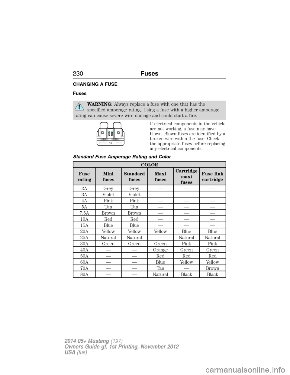
If electrical components in the vehicle
are not working, a fuse may have
blown. Blown fuses are identified by a
broken wire within the fuse. Check
the appropriate fuses before replacing
any electrical components.
Standard Fuse Amperage Rating and Color
COLOR
Fuse
ratingMini
fusesStandard
fusesMaxi
fusesCartridge
maxi
fusesFuse link
cartridge
2A Grey Grey — — —
3A Violet Violet — — —
4A Pink Pink — — —
5A Tan Tan — — —
7.5A Brown Brown — — —
10A Red Red — — —
15A Blue Blue — — —
20A Yellow Yellow Yellow Blue Blue
25A Natural Natural — Natural Natural
30A Green Green Green Pink Pink
40A — — Orange Green Green
50A — — Red Red Red
60A — — Blue Yellow Yellow
70A — — Tan — Brown
80A — — Natural Black Black
15
230Fuses
2014 05+ Mustang(197)
Owners Guide gf, 1st Printing, November 2012
USA(fus)
Page 232 of 461
FUSE SPECIFICATION CHART
Power Distribution Box
WARNING:Always disconnect the battery before servicing high
current fuses.
WARNING:To reduce risk of electrical shock, always replace
the cover to the power distribution box before reconnecting the
battery or refilling fluid reservoirs.
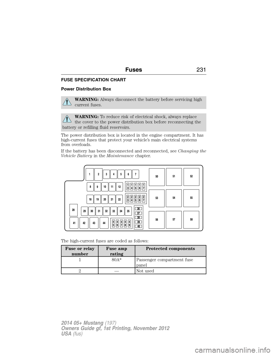
The power distribution box is located in the engine compartment. It has
high-current fuses that protect your vehicle’s main electrical systems
from overloads.
If the battery has been disconnected and reconnected, seeChanging the
Vehicle Batteryin theMaintenancechapter.
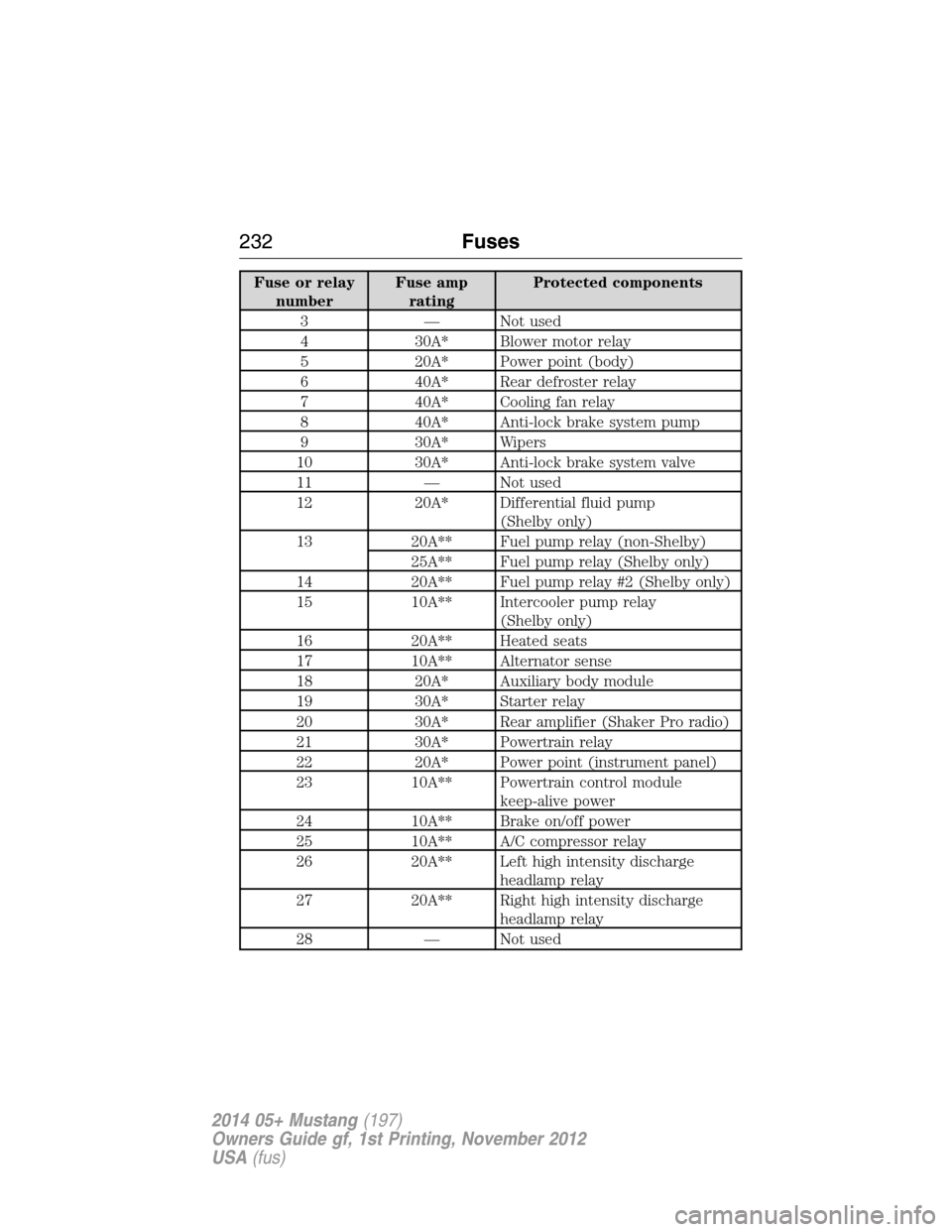
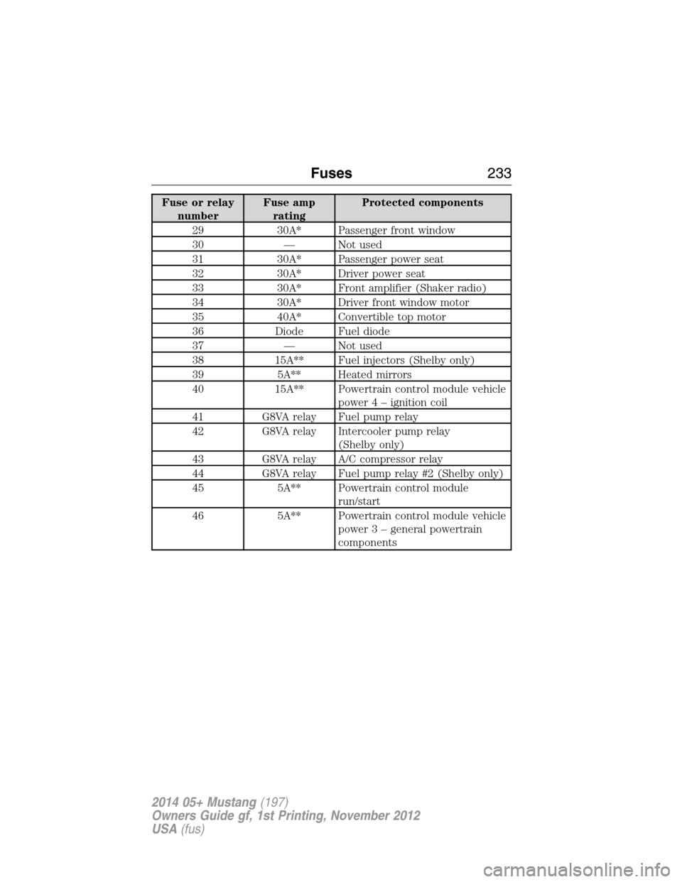
The high-current fuses are coded as follows:
Fuse or relay
numberFuse amp
ratingProtected components
1 80A* Passenger compartment fuse
panel
2 — Not used
Fuses231
2014 05+ Mustang(197)
Owners Guide gf, 1st Printing, November 2012
USA(fus)
Page 233 of 461
Fuse or relay
numberFuse amp
ratingProtected components
3 — Not used
4 30A* Blower motor relay
5 20A* Power point (body)
6 40A* Rear defroster relay
7 40A* Cooling fan relay
8 40A* Anti-lock brake system pump
9 30A* Wipers
10 30A* Anti-lock brake system valve
11 — Not used
12 20A* Differential fluid pump
(Shelby only)
13 20A** Fuel pump relay (non-Shelby)
25A** Fuel pump relay (Shelby only)
14 20A** Fuel pump relay #2 (Shelby only)
15 10A** Intercooler pump relay
(Shelby only)
16 20A** Heated seats
17 10A** Alternator sense
18 20A* Auxiliary body module
19 30A* Starter relay
20 30A* Rear amplifier (Shaker Pro radio)
21 30A* Powertrain relay
22 20A* Power point (instrument panel)
23 10A** Powertrain control module
keep-alive power
24 10A** Brake on/off power
25 10A** A/C compressor relay
26 20A** Left high intensity discharge
headlamp relay
27 20A** Right high intensity discharge
headlamp relay
28 — Not used
232Fuses
2014 05+ Mustang(197)
Owners Guide gf, 1st Printing, November 2012
USA(fus)
Page 234 of 461
Fuse or relay
numberFuse amp
ratingProtected components
29 30A* Passenger front window
30 — Not used
31 30A* Passenger power seat
32 30A* Driver power seat
33 30A* Front amplifier (Shaker radio)
34 30A* Driver front window motor
35 40A* Convertible top motor
36 Diode Fuel diode
37 — Not used
38 15A** Fuel injectors (Shelby only)
39 5A** Heated mirrors
40 15A** Powertrain control module vehicle
power4–ignition coil
41 G8VA relay Fuel pump relay
42 G8VA relay Intercooler pump relay
(Shelby only)
43 G8VA relay A/C compressor relay
44 G8VA relay Fuel pump relay #2 (Shelby only)
45 5A** Powertrain control module
run/start
46 5A** Powertrain control module vehicle
power 3 – general powertrain
components
Fuses233
2014 05+ Mustang(197)
Owners Guide gf, 1st Printing, November 2012
USA(fus)
Page 235 of 461
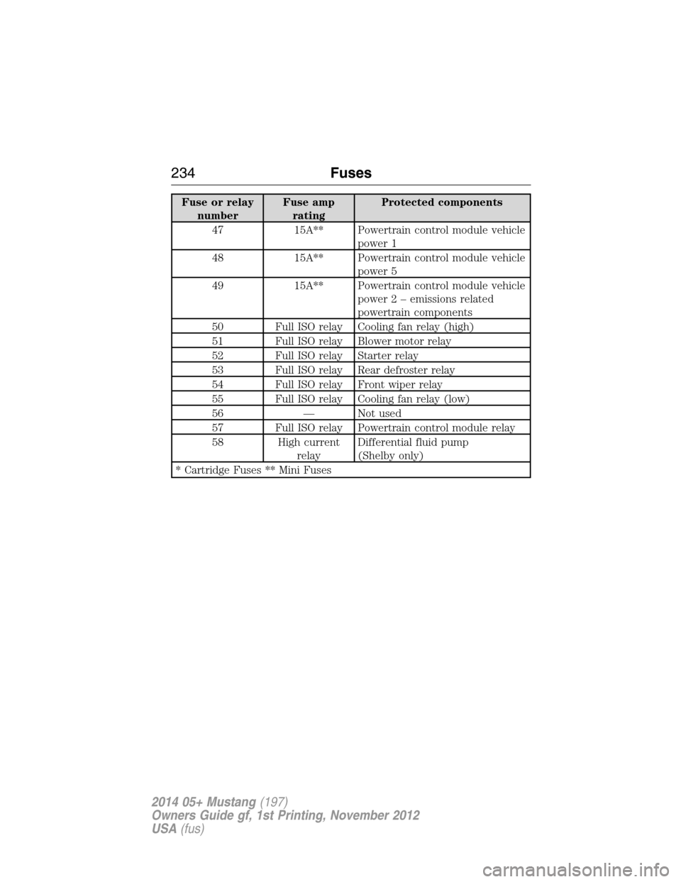
Fuse or relay
numberFuse amp
ratingProtected components
47 15A** Powertrain control module vehicle
power 1
48 15A** Powertrain control module vehicle
power 5
49 15A** Powertrain control module vehicle
power 2 – emissions related
powertrain components
50 Full ISO relay Cooling fan relay (high)
51 Full ISO relay Blower motor relay
52 Full ISO relay Starter relay
53 Full ISO relay Rear defroster relay
54 Full ISO relay Front wiper relay
55 Full ISO relay Cooling fan relay (low)
56 — Not used
57 Full ISO relay Powertrain control module relay
58 High current
relayDifferential fluid pump
(Shelby only)
* Cartridge Fuses ** Mini Fuses
234Fuses
2014 05+ Mustang(197)
Owners Guide gf, 1st Printing, November 2012
USA(fus)
Page 236 of 461
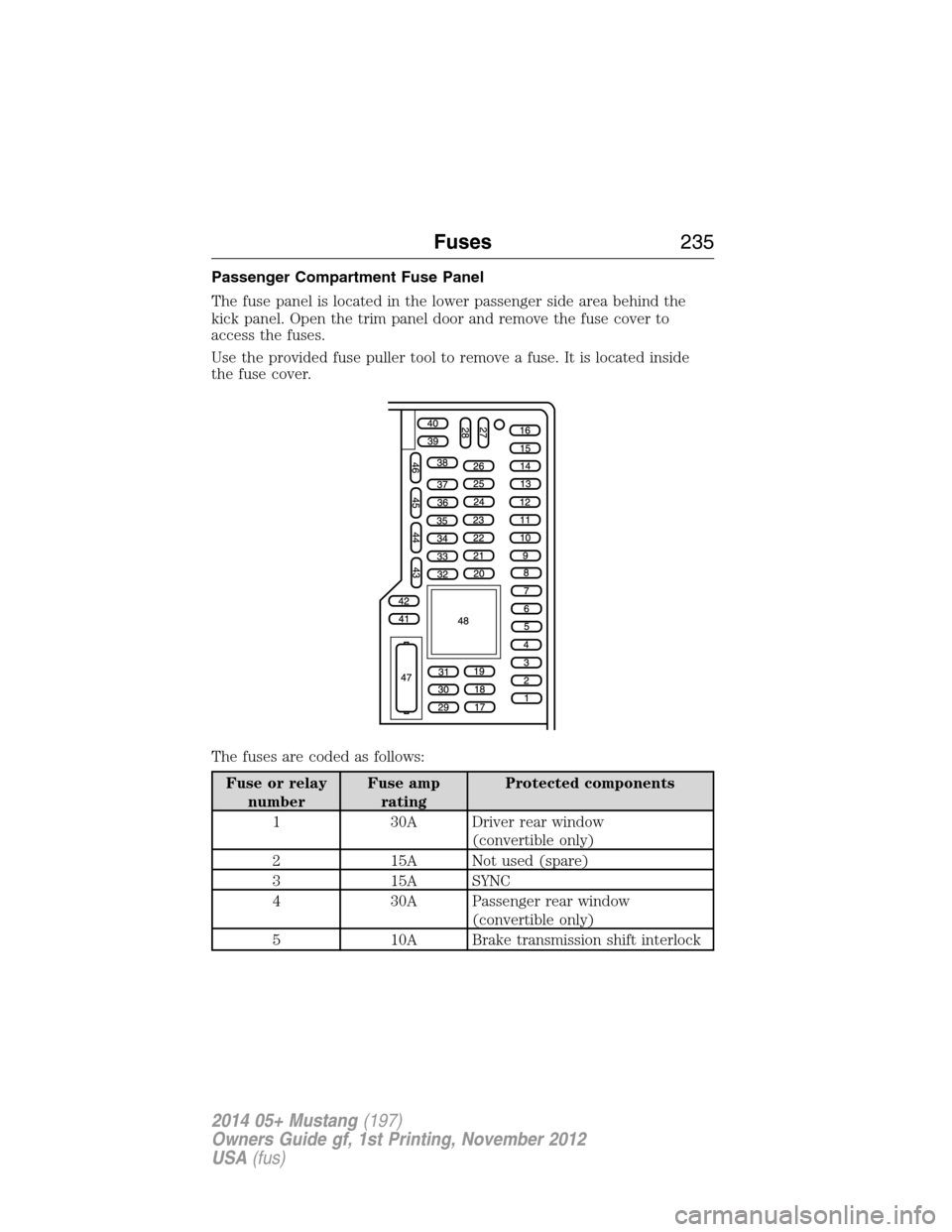
Passenger Compartment Fuse Panel
The fuse panel is located in the lower passenger side area behind the
kick panel. Open the trim panel door and remove the fuse cover to
access the fuses.
Use the provided fuse puller tool to remove a fuse. It is located inside
the fuse cover.
The fuses are coded as follows:
Fuse or relay
numberFuse amp
ratingProtected components
1 30A Driver rear window
(convertible only)
2 15A Not used (spare)
3 15A SYNC
4 30A Passenger rear window
(convertible only)
5 10A Brake transmission shift interlock
Fuses235
2014 05+ Mustang(197)
Owners Guide gf, 1st Printing, November 2012
USA(fus)
Page 237 of 461
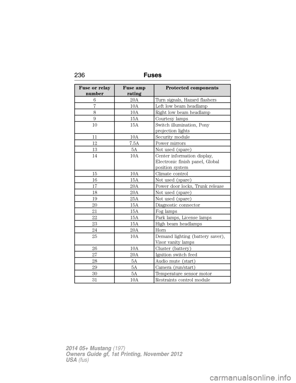
Fuse or relay
numberFuse amp
ratingProtected components
6 20A Turn signals, Hazard flashers
7 10A Left low beam headlamp
8 10A Right low beam headlamp
9 15A Courtesy lamps
10 15A Switch illumination, Pony
projection lights
11 10A Security module
12 7.5A Power mirrors
13 5A Not used (spare)
14 10A Center information display,
Electronic finish panel, Global
position system
15 10A Climate control
16 15A Not used (spare)
17 20A Power door locks, Trunk release
18 20A Not used (spare)
19 25A Not used (spare)
20 15A Diagnostic connector
21 15A Fog lamps
22 15A Park lamps, License lamps
23 15A High beam headlamps
24 20A Horn
25 10A Demand lighting (battery saver),
Visor vanity lamps
26 10A Cluster (battery)
27 20A Ignition switch feed
28 5A Audio mute (start)
29 5A Camera (run/start)
30 5A Temperature sensor motor
31 10A Restraints control module
236Fuses
2014 05+ Mustang(197)
Owners Guide gf, 1st Printing, November 2012
USA(fus)
Page 238 of 461
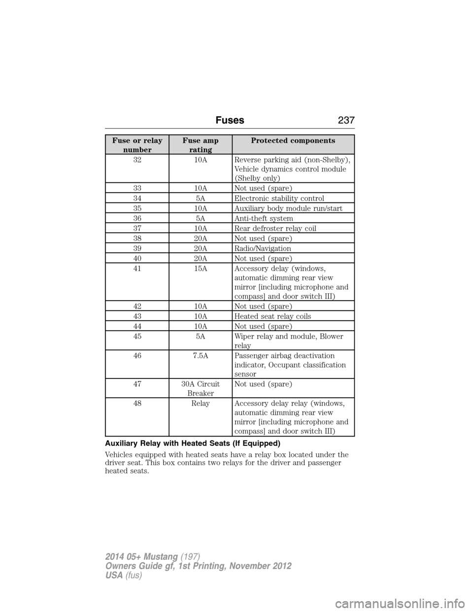
Fuse or relay
numberFuse amp
ratingProtected components
32 10A Reverse parking aid (non-Shelby),
Vehicle dynamics control module
(Shelby only)
33 10A Not used (spare)
34 5A Electronic stability control
35 10A Auxiliary body module run/start
36 5A Anti-theft system
37 10A Rear defroster relay coil
38 20A Not used (spare)
39 20A Radio/Navigation
40 20A Not used (spare)
41 15A Accessory delay (windows,
automatic dimming rear view
mirror [including microphone and
compass] and door switch III)
42 10A Not used (spare)
43 10A Heated seat relay coils
44 10A Not used (spare)
45 5A Wiper relay and module, Blower
relay
46 7.5A Passenger airbag deactivation
indicator, Occupant classification
sensor
47 30A Circuit
BreakerNot used (spare)
48 Relay Accessory delay relay (windows,
automatic dimming rear view
mirror [including microphone and
compass] and door switch III)
Auxiliary Relay with Heated Seats (If Equipped)
Vehicles equipped with heated seats have a relay box located under the
driver seat. This box contains two relays for the driver and passenger
heated seats.
Fuses237
2014 05+ Mustang(197)
Owners Guide gf, 1st Printing, November 2012
USA(fus)
Page 239 of 461
GENERAL INFORMATION
Have your vehicle serviced regularly to help maintain its roadworthiness
and resale value. There is a large network of Ford authorized dealers
who are there to help you with their professional servicing expertise.
We believe that their specially trained technicians are best qualified to
service your vehicle properly and expertly. They are supported by a wide
range of highly specialized tools developed specifically for servicing your
vehicle.
To help you service your vehicle, we provideScheduled Maintenance
Informationwhich makes tracking routine service easy.
If your vehicle requires professional service, your authorized dealer
can provide the necessary parts and service. Check your warranty
information to find out which parts and services are covered.
Use only recommended fuels, lubricants, fluids and service parts
conforming to specifications. Motorcraft® parts are designed and built
to provide the best performance in your vehicle.
Precautions
•Do not work on a hot engine.
•Make sure that nothing gets caught in moving parts.
•Do not work on a vehicle with the engine running in an enclosed
space, unless you are sure you have enough ventilation.
•Keep all open flames and other burning material (such as cigarettes)
away from the battery and all fuelrelated parts.
Working with the Engine Off
1. Set the parking brake and shift toP(Park).
2. Turn off the engine and remove the key (if equipped).
3. Block the wheels.
238Maintenance
2014 05+ Mustang(197)
Owners Guide gf, 1st Printing, November 2012
USA(fus)
Page 240 of 461
Working with the Engine On
WARNING:To reduce the risk of vehicle damage or personal
burn injuries, do not start your engine with the air cleaner
removed and do not remove it while the engine is running.
1. Set the parking brake and shift to positionP.
2. Block the wheels.
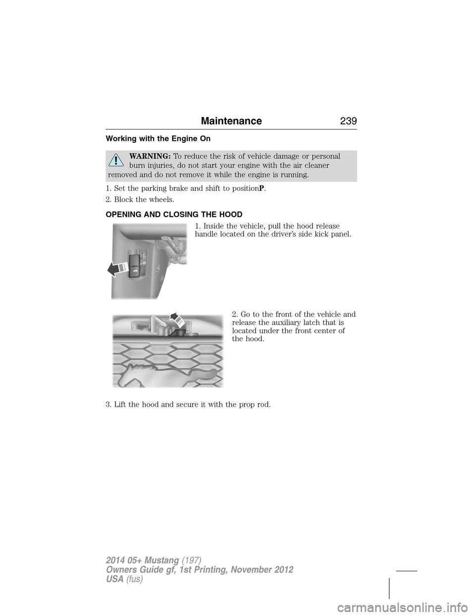
OPENING AND CLOSING THE HOOD
1. Inside the vehicle, pull the hood release
handle located on the driver’s side kick panel.
2. Go to the front of the vehicle and
release the auxiliary latch that is
located under the front center of
the hood.
3. Lift the hood and secure it with the prop rod.
Maintenance239
2014 05+ Mustang(197)
Owners Guide gf, 1st Printing, November 2012
USA(fus)