sensor FORD SIERRA 1983 1.G Bodywork And Fittings Workshop Manual
[x] Cancel search | Manufacturer: FORD, Model Year: 1983, Model line: SIERRA, Model: FORD SIERRA 1983 1.GPages: 22, PDF Size: 1.2 MB
Page 5 of 22

Models up to 1987
1Working in the engine compartment,
disconnect the cable from the bonnet lock by
pulling the cable sheath end fitting from its
bracket, then releasing the end fitting from the
lock lever.
2Remove the three securing screws and
withdraw the lock from the front panel.
3Refitting is a reversal of removal.
Models from 1987
4Remove the radiator grille panel.
5Disconnect the cable from the bonnet lock
by pulling the cable sheath end fitting from its
bracket, then releasing the end fitting from the
lock lever.
6Detach the bracing strut from the lock by
removing the screw, then remove the two
securing screws and withdraw the lock from
the front panel.
7Refitting is a reversal of removal.
Removal
1Open the boot lid, and place protective
covers (old rags or cardboard) beneath the
corners of the lid, and over the rear wings to
prevent damage to the paintwork.
2Where applicable, disconnect the wiring
from the lock solenoid and “boot lid ajar”
sensor, after disconnecting the battery
negative lead.
3Release the wiring loom grommets, taking
care not to lose them, then tie string to the
wiring loom(s), and pull the loom(s) through
the boot lid. Leave the string(s) in position in
the boot lid to aid refitting of the loom(s).
4Mark the location of the hinges on the
underside of the lid using a soft pencil or
masking type, then loosen the four hinge bolts.5With the help of an assistant, remove the
bolts and lift the boot lid from the vehicle.
Refitting
6Refitting is a reversal of removal, bearing in
mind the following points.
7Adjust the hinges to their original marked
positions before tightening the bolts.
8On completion, check that the boot lid is
central within its aperture and aligned with the
surrounding bodywork. Re-adjust the hinges
to give satisfactory alignment if necessary.
9Check that the lock striker engages fully in
the lock, and if necessary adjust the position
of the lock striker.
Removal
1With the boot lid raised, remove the lock
barrel retaining clip.
2Where applicable, disconnect the operating
lever from the central locking solenoid/motor,
then withdraw the lock barrel.
3Remove the three retaining screws from the
lock assembly, if necessary loosening the
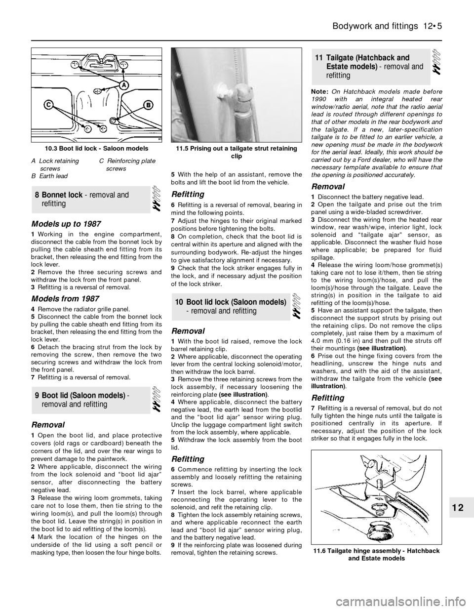
reinforcing plate (see illustration).
4Where applicable, disconnect the battery
negative lead, the earth lead from the bootlid
and the “boot lid ajar” sensor wiring plug.
Unclip the luggage compartment light switch
from the lock assembly, where applicable.
5Withdraw the lock assembly from the boot
lid.
Refitting
6Commence refitting by inserting the lock
assembly and loosely refitting the retaining
screws.
7Insert the lock barrel, where applicable
reconnecting the operating lever to the
solenoid, and refit the retaining clip.
8Tighten the lock assembly retaining screws,
and where applicable reconnect the earth
lead and “boot lid ajar” sensor wiring plug,
and the battery negative lead.
9If the reinforcing plate was loosened during
removal, tighten the retaining screws.Note: On Hatchback models made before
1990 with an integral heated rear
window/radio aerial, note that the radio aerial
lead is routed through different openings to
that of other models in the rear bodywork and
the tailgate. If a new, later-specification
tailgate is to be fitted to an earlier vehicle, a
new opening must be made in the bodywork
for the aerial lead. Ideally, this work should be
carried out by a Ford dealer, who will have the
necessary template available to ensure that
the opening is positioned accurately.
Removal
1Disconnect the battery negative lead.
2Open the tailgate and prise out the trim
panel using a wide-bladed screwdriver.
3Disconnect the wiring from the heated rear
window, rear wash/wipe, interior light, lock
solenoid and “tailgate ajar” sensor, as
applicable. Disconnect the washer fluid hose
where applicable; be prepared for fluid
spillage.
4Release the wiring loom/hose grommet(s)
taking care not to lose it/them, then tie string
to the wiring loom(s)/hose, and pull the
loom(s)/hose through the tailgate. Leave the
string(s) in position in the tailgate to aid
refitting of the loom(s)/hose.
5Have an assistant support the tailgate, then
disconnect the support struts by prising out
the retaining clips. Do not remove the clips
completely, just raise them by a maximum of
4.0 mm (0.16 in) and then pull the struts off
their mountings (see illustration).
6Prise out the hinge fixing covers from the
headlining, unscrew the hinge nuts and
washers, and with the aid of the assistant,
withdraw the tailgate from the vehicle (see
illustration).
Refitting
7Refitting is a reversal of removal, but do not
fully tighten the hinge nuts until the tailgate is
positioned centrally in its aperture. If
necessary, adjust the position of the lock
striker so that it engages fully in the lock.
11Tailgate (Hatchback and
Estate models) - removal and
refitting
10Boot lid lock (Saloon models)
- removal and refitting
9Boot lid (Saloon models) -
removal and refitting
8Bonnet lock - removal and
refitting
Bodywork and fittings 12•5
12
11.6 Tailgate hinge assembly - Hatchback
and Estate models
11.5 Prising out a tailgate strut retaining
clip10.3 Boot lid lock - Saloon models
A Lock retaining
screws
B Earth leadC Reinforcing plate
screws
Page 6 of 22

Removal
1Open the tailgate and prise out the trim
panel using a wide-bladed screwdriver(see
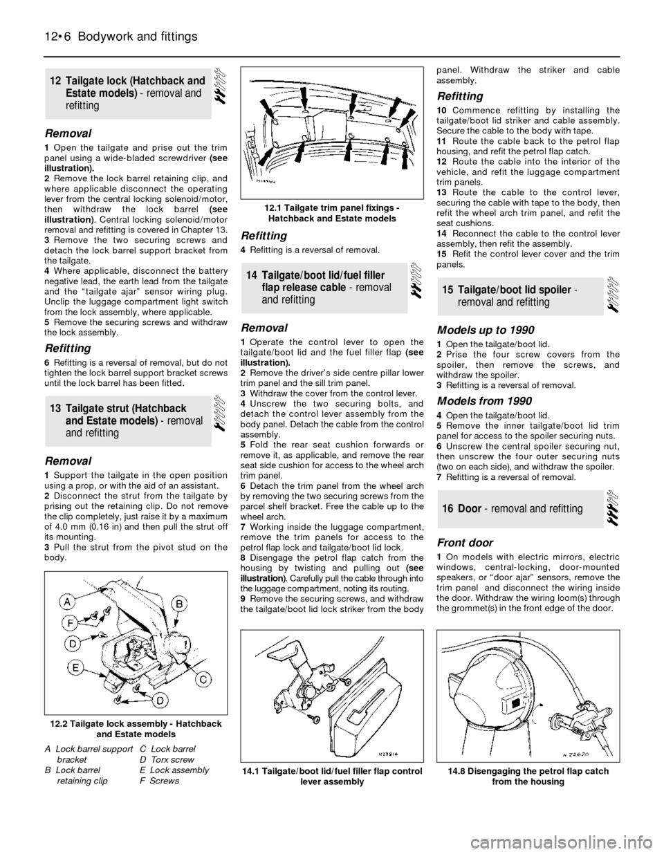
illustration).
2Remove the lock barrel retaining clip, and
where applicable disconnect the operating
lever from the central locking solenoid/motor,
then withdraw the lock barrel (see
illustration). Central locking solenoid/motor
removal and refitting is covered in Chapter 13.
3Remove the two securing screws and
detach the lock barrel support bracket from
the tailgate.
4Where applicable, disconnect the battery
negative lead, the earth lead from the tailgate
and the “tailgate ajar” sensor wiring plug.
Unclip the luggage compartment light switch
from the lock assembly, where applicable.
5Remove the securing screws and withdraw
the lock assembly.
Refitting
6Refitting is a reversal of removal, but do not
tighten the lock barrel support bracket screws
until the lock barrel has been fitted.
Removal
1Support the tailgate in the open position
using a prop, or with the aid of an assistant.
2Disconnect the strut from the tailgate by
prising out the retaining clip. Do not remove
the clip completely, just raise it by a maximum
of 4.0 mm (0.16 in) and then pull the strut off
its mounting.
3Pull the strut from the pivot stud on the
body.
Refitting
4Refitting is a reversal of removal.
Removal
1Operate the control lever to open the
tailgate/boot lid and the fuel filler flap (see
illustration).
2Remove the driver’s side centre pillar lower
trim panel and the sill trim panel.
3Withdraw the cover from the control lever.
4Unscrew the two securing bolts, and
detach the control lever assembly from the
body panel. Detach the cable from the control
assembly.
5Fold the rear seat cushion forwards or
remove it, as applicable, and remove the rear
seat side cushion for access to the wheel arch
trim panel.
6Detach the trim panel from the wheel arch
by removing the two securing screws from the
parcel shelf bracket. Free the cable up to the
wheel arch.
7Working inside the luggage compartment,
remove the trim panels for access to the
petrol flap lock and tailgate/boot lid lock.
8Disengage the petrol flap catch from the
housing by twisting and pulling out (see
illustration). Carefully pull the cable through into
the luggage compartment, noting its routing.
9Remove the securing screws, and withdraw
the tailgate/boot lid lock striker from the bodypanel. Withdraw the striker and cable
assembly.
Refitting
10Commence refitting by installing the
tailgate/boot lid striker and cable assembly.
Secure the cable to the body with tape.
11Route the cable back to the petrol flap
housing, and refit the petrol flap catch.
12Route the cable into the interior of the
vehicle, and refit the luggage compartment
trim panels.
13Route the cable to the control lever,
securing the cable with tape to the body, then
refit the wheel arch trim panel, and refit the
seat cushions.
14Reconnect the cable to the control lever
assembly, then refit the assembly.
15Refit the control lever cover and the trim
panels.
Models up to 1990
1Open the tailgate/boot lid.
2Prise the four screw covers from the
spoiler, then remove the screws, and
withdraw the spoiler.
3Refitting is a reversal of removal.
Models from 1990
4Open the tailgate/boot lid.
5Remove the inner tailgate/boot lid trim
panel for access to the spoiler securing nuts.
6Unscrew the central spoiler securing nut,
then unscrew the four outer securing nuts
(two on each side), and withdraw the spoiler.
7Refitting is a reversal of removal.
Front door
1On models with electric mirrors, electric
windows, central-locking, door-mounted
speakers, or “door ajar” sensors, remove the
trim panel and disconnect the wiring inside
the door. Withdraw the wiring loom(s) through
the grommet(s) in the front edge of the door.
16Door - removal and refitting
15Tailgate/boot lid spoiler -
removal and refitting
14Tailgate/boot lid/fuel filler
flap release cable - removal
and refitting
13Tailgate strut (Hatchback
and Estate models) - removal
and refitting
12Tailgate lock (Hatchback and
Estate models) - removal and
refitting
12•6Bodywork and fittings
14.1 Tailgate/boot lid/fuel filler flap control
lever assembly14.8 Disengaging the petrol flap catch
from the housing
12.2 Tailgate lock assembly - Hatchback
and Estate models
A Lock barrel support
bracket
B Lock barrel
retaining clipC Lock barrel
D Torx screw
E Lock assembly
F Screws
12.1 Tailgate trim panel fixings -
Hatchback and Estate models
Page 7 of 22

2Unscrew and remove the bolt securing the
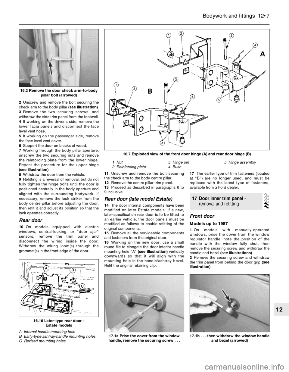
check arm to the body pillar (see illustration).
3Remove the two securing screws, and
withdraw the side trim panel from the footwell.
4If working on the driver’s side, remove the
lower facia panels and disconnect the face
level vent hose.
5If working on the passenger side, remove
the face level vent cover.
6Support the door on blocks of wood.
7Working through the body pillar aperture,
unscrew the two securing nuts and remove
the reinforcing plate from the lower hinge.
Repeat the procedure for the upper hinge
(see illustration).
8Withdraw the door from the vehicle.
9Refitting is a reversal of removal, but do not
fully tighten the hinge bolts until the door is
positioned centrally in the body aperture and
aligned with the surrounding bodywork. If
necessary, remove the lock striker from the
body centre pillar before adjusting the door,
then refit it and adjust its position so that the
lock operates correctly.
Rear door
10On models equipped with electric
windows, central-locking, or “door ajar”
sensors, remove the trim panel and
disconnect the wiring inside the door.
Withdraw the wiring loom(s) through the
grommet(s) in the front edge of the door.11Unscrew and remove the bolt securing
the check arm to the body centre pillar.
12Remove the centre pillar trim panel.
13Proceed as described in paragraphs 6 to
9 inclusive.
Rear door (late model Estate)
14The door internal components have been
modified on later Estate models. If a new,
later-specification rear door is to be fitted to
an earlier vehicle, the door panels must be
modified as follows to enable refitting of the
original components.
15Remove all the serviceable components
and fasteners from the original door.
16Working on the new door, use a small
round file to elongate the door interior handle
mounting hole “A” (see illustration)vertically
downwards so that it will align with the
mounting hole in the handle/ashtray bezel.
Refit the original retaining clip.17The earlier type of trim fasteners (located
at “B”) are no longer used, and must be
replaced with the latest type of fasteners,
available from a Ford dealer.
Front door
Models up to 1987
1On models with manually-operated
windows, prise the cover from the window
regulator handle, note the position of the
handle with the window fully shut, then
remove the securing screw and withdraw the
handle and bezel (see illustrations).
2Remove the securing screw and withdraw
the trim panel from behind the door grip (see
illustration).
17Door inner trim panel -
removal and refitting
Bodywork and fittings 12•7
12
16.16 Later-type rear door -
Estate models
A Internal handle mounting hole
B Early-type ashtray/handle mounting holes
C Revised mounting holes17.1a Prise the cover from the window
handle, remove the securing screw . . .17.1b . . . then withdraw the window handle
and bezel (arrowed)
16.2 Remove the door check arm-to-body
pillar bolt (arrowed)
1 Nut
2 Reinforcing plate3 Hinge pin
4 Bush5 Hinge assembly
16.7 Exploded view of the front door hinge (A) and rear door hinge (B)
Page 10 of 22

3Remove the window channel extension
screw from the bottom rear corner of the
door, and withdraw the channel through the
lower door aperture.
4Working inside the door aperture, pull out
the lock barrel retaining clip using pliers, then
unhook the lock operating rod from the barrel,
and withdraw the barrel from outside the door
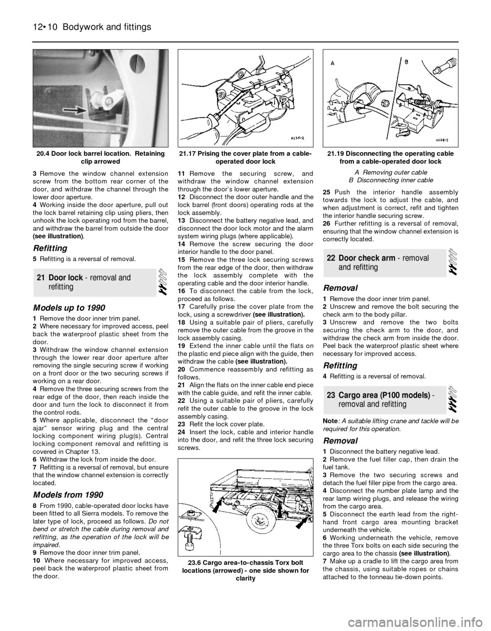
(see illustration).
Refitting
5Refitting is a reversal of removal.
Models up to 1990
1Remove the door inner trim panel.
2Where necessary for improved access, peel
back the waterproof plastic sheet from the
door.
3Withdraw the window channel extension
through the lower rear door aperture after
removing the single securing screw if working
on a front door or the two securing screws if
working on a rear door.
4Remove the three securing screws from the
rear edge of the door, then reach inside the
door and turn the lock to disconnect it from
the control rods.
5Where applicable, disconnect the “door
ajar” sensor wiring plug and the central
locking component wiring plug(s). Central
locking component removal and refitting is
covered in Chapter 13.
6Withdraw the lock from inside the door.
7Refitting is a reversal of removal, but ensure
that the window channel extension is correctly
located.
Models from 1990
8From 1990, cable-operated door locks have
been fitted to all Sierra models. To remove the
later type of lock, proceed as follows. Do not
bend or stretch the cable during removal and
refitting, as the operation of the lock will be
impaired.
9Remove the door inner trim panel.
10Where necessary for improved access,
peel back the waterproof plastic sheet from
the door.11Remove the securing screw, and
withdraw the window channel extension
through the door’s lower aperture.
12Disconnect the door outer handle and the
lock barrel (front doors) operating rods at the
lock assembly.
13Disconnect the battery negative lead, and
disconnect the door lock motor and the alarm
system wiring plugs (where applicable).
14Remove the screw securing the door
interior handle to the door panel.
15Remove the three lock securing screws
from the rear edge of the door, then withdraw
the lock assembly complete with the
operating cable and the door interior handle.
16To disconnect the cable from the lock,
proceed as follows.
17Carefully prise the cover plate from the
lock, using a screwdriver(see illustration).
18Using a suitable pair of pliers, carefully
remove the outer cable from the groove in the
lock assembly casing.
19Extend the inner cable until the flats on
the plastic end piece align with the guide, then
withdraw the cable (see illustration).
20Commence reassembly and refitting as
follows.
21Align the flats on the inner cable end piece
with the cable guide, and refit the inner cable.
22Using a suitable pair of pliers, carefully
refit the outer cable to the groove in the lock
assembly casing.
23Refit the lock cover plate.
24Insert the lock, cable and interior handle
into the door, and refit the three lock securing
screws. 25Push the interior handle assembly
towards the lock to adjust the cable, and
when adjustment is correct, refit and tighten
the interior handle securing screw.
26Further refitting is a reversal of removal,
ensuring that the window channel extension is
correctly located.
Removal
1Remove the door inner trim panel.
2Unscrew and remove the bolt securing the
check arm to the body pillar.
3Unscrew and remove the two bolts
securing the check arm to the door, and
withdraw the check arm from inside the door.
Peel back the waterproof plastic sheet where
necessary for improved access.
Refitting
4Refitting is a reversal of removal.
Note: A suitable lifting crane and tackle will be
required for this operation.
Removal
1Disconnect the battery negative lead.
2Remove the fuel filler cap, then drain the
fuel tank.
3Remove the two securing screws and
detach the fuel filler pipe from the cargo area.
4Disconnect the number plate lamp and the
rear lamp wiring plugs, and release the wiring
from the cargo area.
5Disconnect the earth lead from the right-
hand front cargo area mounting bracket
underneath the vehicle.
6Working underneath the vehicle, remove
the three Torx bolts on each side securing the
cargo area to the chassis (see illustration).
7Make up a cradle to lift the cargo area from
the chassis, using suitable ropes or chains
attached to the tonneau tie-down points.
23Cargo area (P100 models) -
removal and refitting
22Door check arm - removal
and refitting
21Door lock - removal and
refitting
12•10Bodywork and fittings
21.17 Prising the cover plate from a cable-
operated door lock
23.6 Cargo area-to-chassis Torx bolt
locations (arrowed) - one side shown for
clarity
21.19 Disconnecting the operating cable
from a cable-operated door lock
A Removing outer cable
B Disconnecting inner cable
20.4 Door lock barrel location. Retaining
clip arrowed