fuel filter location FORD SIERRA 1985 1.G Routine Manintenance And Servicing Workshop Manual
[x] Cancel search | Manufacturer: FORD, Model Year: 1985, Model line: SIERRA, Model: FORD SIERRA 1985 1.GPages: 22, PDF Size: 1.26 MB
Page 5 of 22

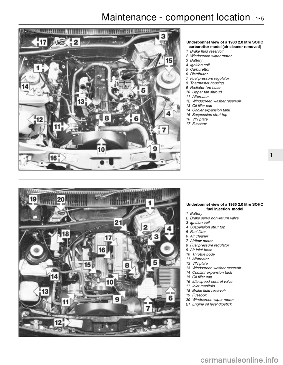
Maintenance - component location 1•5
1
Underbonnet view of a 1985 2.0 litre SOHC
fuel injection model
1 Battery
2 Brake servo non-return valve
3 Ignition coil
4 Suspension strut top
5 Fuel filter
6 Air cleaner
7 Airflow meter
8 Fuel pressure regulator
9 Air inlet hose
10 Throttle body
11 Alternator
12 VIN plate
13 Windscreen washer reservoir
14 Coolant expansion tank
15 Oil filler cap
16 Idle speed control valve
17 Inlet manifold
18 Brake fluid reservoir
19 Fusebox
20 Windscreen wiper motor
21 Engine oil level dipstick
Underbonnet view of a 1983 2.0 litre SOHC
carburettor model (air cleaner removed)
1 Brake fluid reservoir
2 Windscreen wiper motor
3 Battery
4 Ignition coil
5 Carburettor
6 Distributor
7 Fuel pressure regulator
8 Thermostat housing
9 Radiator top hose
10 Upper fan shroud
11 Alternator
12 Windscreen washer reservoir
13 Oil filler cap
14 Cooler expansion tank
15 Suspension strut top
16 VIN plate
17 Fusebox
Page 9 of 22

General information
This Chapter is designed to help the home
mechanic maintain his/her vehicle for safety,
economy, long life and peak performance.
The Chapter contains a master
maintenance schedule, followed by Sections
dealing specifically with each task in the
schedule. Visual checks, adjustments,
component renewal and other helpful items
are included. Refer to the accompanying
illustrations of the engine compartment and
the underside of the vehicle for the locations
of the various components.
Servicing your vehicle in accordance with
the mileage/time maintenance schedule and
the following Sections will provide a planned
maintenance programme, which should result
in a long and reliable service life. This is a
comprehensive plan, so maintaining some
items but not others at the specified service
intervals, will not produce the same results.
As you service your vehicle, you will discover
that many of the procedures can - and should -
be grouped together, because of the particular
procedure being performed, or because of the
close proximity of two otherwise-unrelated
components to one another. For example, if
the vehicle is raised for any reason, the exhaust
can be inspected at the same time as thesuspension and steering components.
The first step in this maintenance
programme is to prepare yourself before the
actual work begins. Read through all the
Sections relevant to the work to be carried
out, then make a list and gather together all
the parts and tools required. If a problem is
encountered, seek advice from a parts
specialist, or a dealer service department.
Intensive maintenance
If, from the time the vehicle is new, the
routine maintenance schedule is followed
closely, and frequent checks are made of fluid
levels and high-wear items, as suggested
throughout this manual, the engine will be
kept in relatively good running condition, and
the need for additional work will be minimised.
It is possible that there will be times when
the engine is running poorly due to the lack of
regular maintenance. This is even more likely
if a used vehicle, which has not received
regular and frequent maintenance checks, is
purchased. In such cases, additional work
may need to be carried out, outside of the
regular maintenance intervals.
If engine wear is suspected, a compression
test will provide valuable information
regarding the overall performance of the main
internal components. Such a test can be used
as a basis to decide on the extent of the work
to be carried out. If, for example, a
compression test indicates serious internal
engine wear, conventional maintenance as
described in this Chapter will not greatlyimprove the performance of the engine, and
may prove a waste of time and money, unless
extensive overhaul work is carried out first.
The following series of operations are those
most often required to improve the
performance of a generally poor-running
engine:
Primary operations
a)Clean, inspect and test the battery
b)Check all the engine-related fluids
c)Check the condition and tension of the
auxiliary drivebelt
d)Renew the spark plugs
e)Inspect the distributor cap and HT leads -
as applicable
f)Check the condition of the air cleaner
filter element, and renew if necessary
g)Renew the fuel filter
h)Check the condition of all hoses, and
check for fluid leaks
i)Check the idle speed and mixture settings
- as applicable
If the above operations do not prove fully
effective, carry out the following secondary
operations:
Secondary operations
a)Check the charging system
b)Check the ignition system
c)Check the fuel system
d)Renew the distributor cap and rotor arm -
as applicable
f)Renew the ignition HT leads - as
applicable
2Introduction
See “Weekly checks”.
See “Weekly checks”.See “Weekly checks”.
See “Weekly checks”.See “Weekly checks”.
7Wiper blade check
6Battery electrolyte level check
5Electrical system check
4Tyre checks
3Fluid level checks
1Frequent oil and filter changes are the most
important preventative maintenance
procedures which can be undertaken by the
DIY owner. As engine oil ages, it becomes
diluted and contaminated, which leads to
premature engine wear.
2Before starting this procedure, gather
together all the necessary tools and materials.
Also make sure that you have plenty of clean
rags and newspapers handy, to mop up any
spills. Ideally, the engine oil should be warm,
as it will drain better, and more built-upsludge will be removed with it. Take care,
however, not to touch the exhaust or any
other hot parts of the engine when working
under the vehicle. To avoid any possibility of
scalding, and to protect yourself from
possible skin irritants and other harmful
contaminants in used engine oils, it is
advisable to wear gloves when carrying out
this work. Access to the underside of the
vehicle will be greatly improved if it can be
raised on a lift, driven onto ramps, or jacked
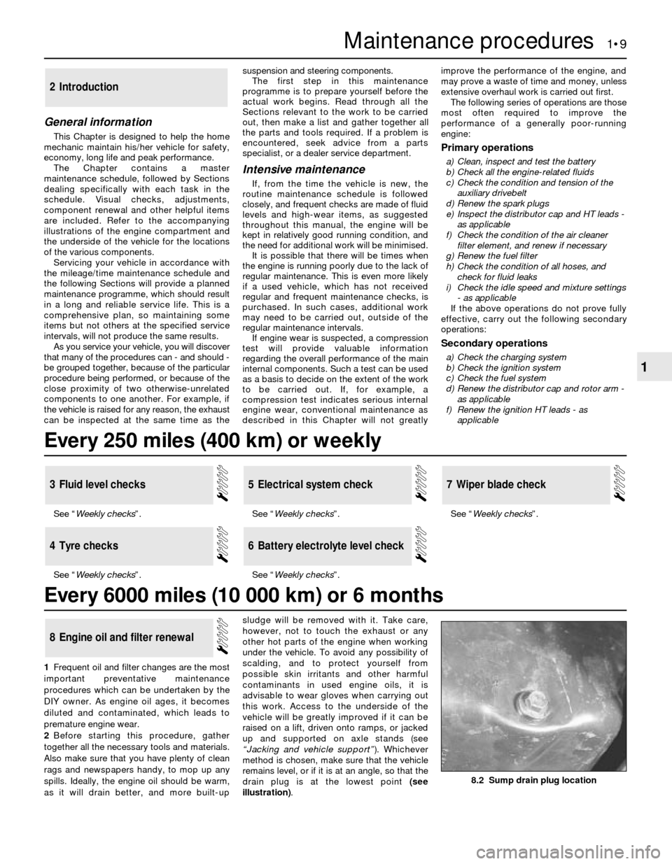
up and supported on axle stands (see
“Jacking and vehicle support”). Whichever
method is chosen, make sure that the vehicle
remains level, or if it is at an angle, so that the
drain plug is at the lowest point (see
illustration).
8Engine oil and filter renewal
Maintenance procedures 1•9
1
8.2 Sump drain plug location
Every 250 miles (400 km) or weekly
Every 6000 miles (10 000 km) or 6 months
Page 21 of 22

6Fit the new filter, ensuring that the arrows on
the filter body point in the direction of fuel flow.
7Tighten the clamp screw, and reconnect
the fuel inlet and outlet unions. Ensure that the
unions are correctly connected.
8Reconnect the battery negative lead, and
check the fuel line unions for leaks,
pressurising the system by switching the
ignition on and off several times.
All models except 2.0 litre SOHC
9Proceed as described for the 2.0 litre SOHCmodels, noting the following points.
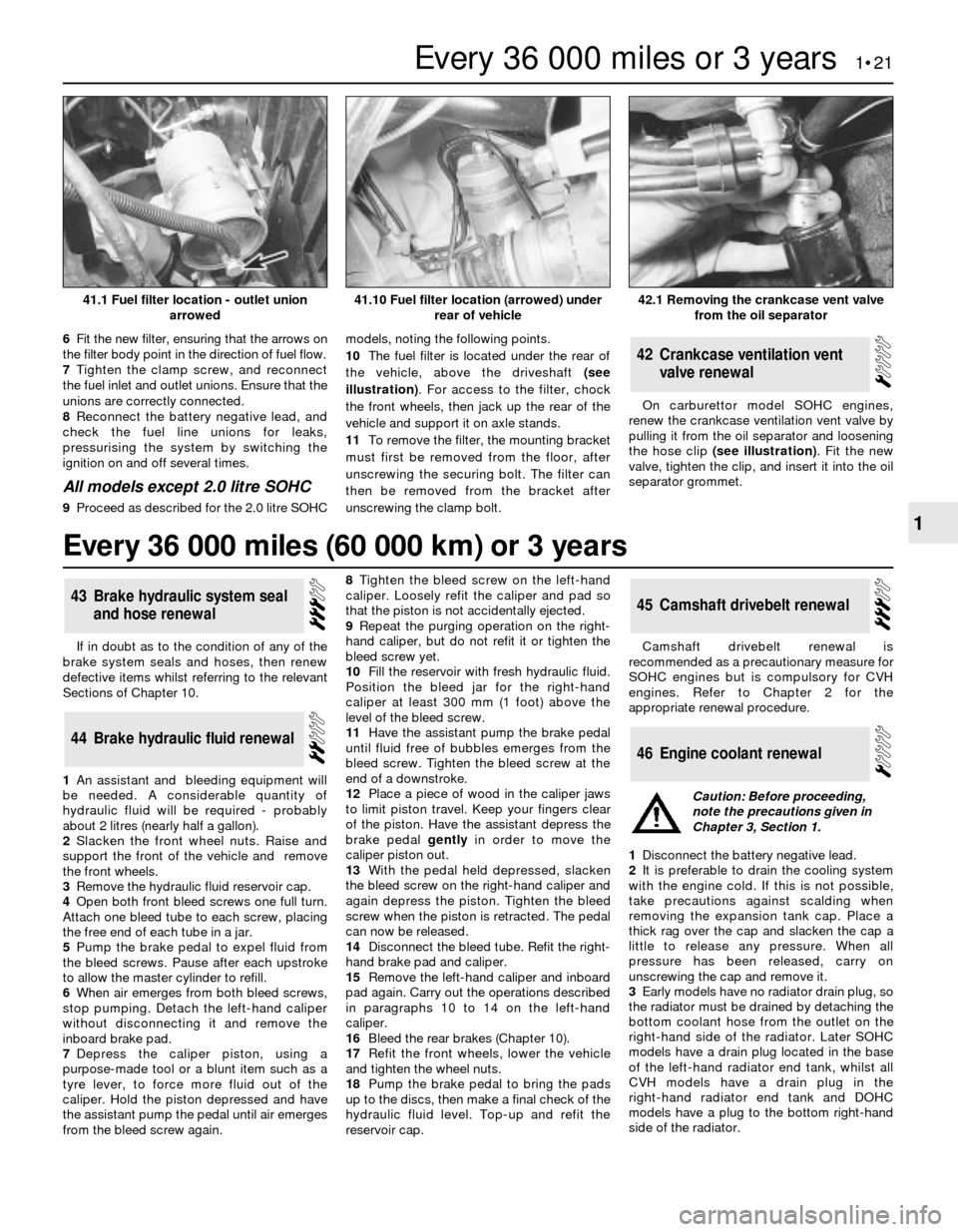
10The fuel filter is located under the rear of
the vehicle, above the driveshaft (see
illustration). For access to the filter, chock
the front wheels, then jack up the rear of the
vehicle and support it on axle stands.
11To remove the filter, the mounting bracket
must first be removed from the floor, after
unscrewing the securing bolt. The filter can
then be removed from the bracket after
unscrewing the clamp bolt.On carburettor model SOHC engines,
renew the crankcase ventilation vent valve by
pulling it from the oil separator and loosening
the hose clip (see illustration). Fit the new
valve, tighten the clip, and insert it into the oil
separator grommet.
42Crankcase ventilation vent
valve renewal
If in doubt as to the condition of any of the
brake system seals and hoses, then renew
defective items whilst referring to the relevant
Sections of Chapter 10.
1An assistant and bleeding equipment will
be needed. A considerable quantity of
hydraulic fluid will be required - probably
about 2 litres (nearly half a gallon).
2Slacken the front wheel nuts. Raise and
support the front of the vehicle and remove
the front wheels.
3Remove the hydraulic fluid reservoir cap.
4Open both front bleed screws one full turn.
Attach one bleed tube to each screw, placing
the free end of each tube in a jar.
5Pump the brake pedal to expel fluid from
the bleed screws. Pause after each upstroke
to allow the master cylinder to refill.
6When air emerges from both bleed screws,
stop pumping. Detach the left-hand caliper
without disconnecting it and remove the
inboard brake pad.
7Depress the caliper piston, using a
purpose-made tool or a blunt item such as a
tyre lever, to force more fluid out of the
caliper. Hold the piston depressed and have
the assistant pump the pedal until air emerges
from the bleed screw again.8Tighten the bleed screw on the left-hand
caliper. Loosely refit the caliper and pad so
that the piston is not accidentally ejected.
9Repeat the purging operation on the right-
hand caliper, but do not refit it or tighten the
bleed screw yet.
10Fill the reservoir with fresh hydraulic fluid.
Position the bleed jar for the right-hand
caliper at least 300 mm (1 foot) above the
level of the bleed screw.
11Have the assistant pump the brake pedal
until fluid free of bubbles emerges from the
bleed screw. Tighten the bleed screw at the
end of a downstroke.
12Place a piece of wood in the caliper jaws
to limit piston travel. Keep your fingers clear
of the piston. Have the assistant depress the
brake pedal gentlyin order to move the
caliper piston out.
13With the pedal held depressed, slacken
the bleed screw on the right-hand caliper and
again depress the piston. Tighten the bleed
screw when the piston is retracted. The pedal
can now be released.
14Disconnect the bleed tube. Refit the right-
hand brake pad and caliper.
15Remove the left-hand caliper and inboard
pad again. Carry out the operations described
in paragraphs 10 to 14 on the left-hand
caliper.
16Bleed the rear brakes (Chapter 10).
17Refit the front wheels, lower the vehicle
and tighten the wheel nuts.
18Pump the brake pedal to bring the pads
up to the discs, then make a final check of the
hydraulic fluid level. Top-up and refit the
reservoir cap.Camshaft drivebelt renewal is
recommended as a precautionary measure for
SOHC engines but is compulsory for CVH
engines. Refer to Chapter 2 for the
appropriate renewal procedure.
1Disconnect the battery negative lead.
2It is preferable to drain the cooling system
with the engine cold. If this is not possible,
take precautions against scalding when
removing the expansion tank cap. Place a
thick rag over the cap and slacken the cap a
little to release any pressure. When all
pressure has been released, carry on
unscrewing the cap and remove it.
3Early models have no radiator drain plug, so
the radiator must be drained by detaching the
bottom coolant hose from the outlet on the
right-hand side of the radiator. Later SOHC
models have a drain plug located in the base
of the left-hand radiator end tank, whilst all
CVH models have a drain plug in the
right-hand radiator end tank and DOHC
models have a plug to the bottom right-hand
side of the radiator.
46Engine coolant renewal
45Camshaft drivebelt renewal
44Brake hydraulic fluid renewal
43Brake hydraulic system seal
and hose renewal
Every 36 000 miles or 3 years 1•21
1
42.1 Removing the crankcase vent valve
from the oil separator41.10 Fuel filter location (arrowed) under
rear of vehicle41.1 Fuel filter location - outlet union
arrowed
Caution: Before proceeding,
note the precautions given in
Chapter 3, Section 1.
Every 36 000 miles (60 000 km) or 3 years