seat adjustment FORD SIERRA 1987 2.G SOHC Engines Workshop Manual
[x] Cancel search | Manufacturer: FORD, Model Year: 1987, Model line: SIERRA, Model: FORD SIERRA 1987 2.GPages: 24, PDF Size: 1.03 MB
Page 16 of 24

Note: A valve spring compressor will be
required during this procedure. New valve
stem oil seals should be used on reassembly.
Dismantling
1With the cylinder head removed, remove
the camshaft.
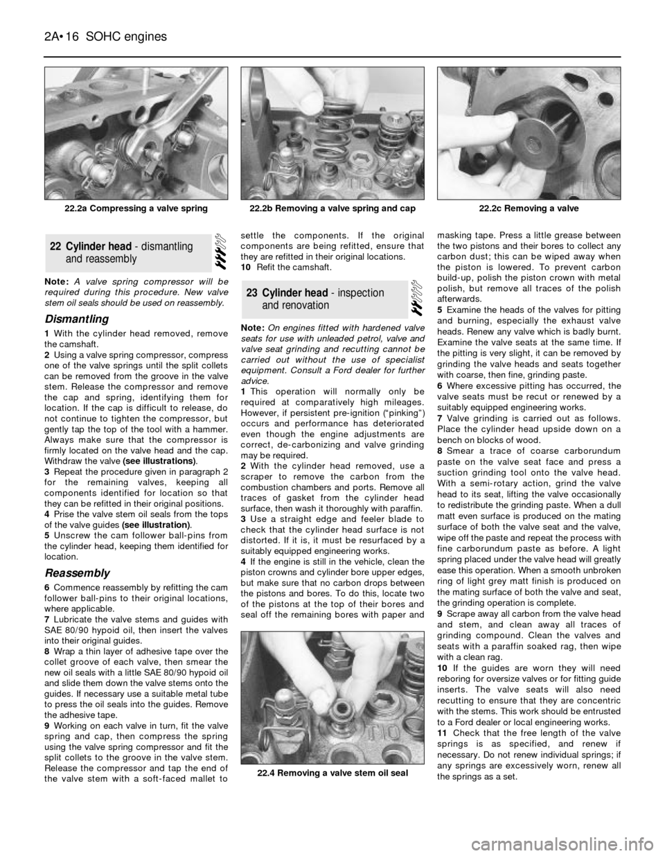
2Using a valve spring compressor, compress
one of the valve springs until the split collets
can be removed from the groove in the valve
stem. Release the compressor and remove
the cap and spring, identifying them for
location. If the cap is difficult to release, do
not continue to tighten the compressor, but
gently tap the top of the tool with a hammer.
Always make sure that the compressor is
firmly located on the valve head and the cap.
Withdraw the valve (see illustrations).
3Repeat the procedure given in paragraph 2
for the remaining valves, keeping all
components identified for location so that
they can be refitted in their original positions.
4Prise the valve stem oil seals from the tops
of the valve guides (see illustration).
5Unscrew the cam follower ball-pins from
the cylinder head, keeping them identified for
location.
Reassembly
6Commence reassembly by refitting the cam
follower ball-pins to their original locations,
where applicable.
7Lubricate the valve stems and guides with
SAE 80/90 hypoid oil, then insert the valves
into their original guides.
8Wrap a thin layer of adhesive tape over the
collet groove of each valve, then smear the
new oil seals with a little SAE 80/90 hypoid oil
and slide them down the valve stems onto the
guides. If necessary use a suitable metal tube
to press the oil seals into the guides. Remove
the adhesive tape.
9Working on each valve in turn, fit the valve
spring and cap, then compress the spring
using the valve spring compressor and fit the
split collets to the groove in the valve stem.
Release the compressor and tap the end of
the valve stem with a soft-faced mallet tosettle the components. If the original
components are being refitted, ensure that
they are refitted in their original locations.
10Refit the camshaft.
Note: On engines fitted with hardened valve
seats for use with unleaded petrol, valve and
valve seat grinding and recutting cannot be
carried out without the use of specialist
equipment. Consult a Ford dealer for further
advice.
1This operation will normally only be
required at comparatively high mileages.
However, if persistent pre-ignition (ÒpinkingÓ)
occurs and performance has deteriorated
even though the engine adjustments are
correct, de-carbonizing and valve grinding
may be required.
2With the cylinder head removed, use a
scraper to remove the carbon from the
combustion chambers and ports. Remove all
traces of gasket from the cylinder head
surface, then wash it thoroughly with paraffin.
3Use a straight edge and feeler blade to
check that the cylinder head surface is not
distorted. If it is, it must be resurfaced by a
suitably equipped engineering works.
4If the engine is still in the vehicle, clean the
piston crowns and cylinder bore upper edges,
but make sure that no carbon drops between
the pistons and bores. To do this, locate two
of the pistons at the top of their bores and
seal off the remaining bores with paper andmasking tape. Press a little grease between
the two pistons and their bores to collect any
carbon dust; this can be wiped away when
the piston is lowered. To prevent carbon
build-up, polish the piston crown with metal
polish, but remove all traces of the polish
afterwards.
5Examine the heads of the valves for pitting
and burning, especially the exhaust valve
heads. Renew any valve which is badly burnt.
Examine the valve seats at the same time. If
the pitting is very slight, it can be removed by
grinding the valve heads and seats together
with coarse, then fine, grinding paste.
6Where excessive pitting has occurred, the
valve seats must be recut or renewed by a
suitably equipped engineering works.
7Valve grinding is carried out as follows.
Place the cylinder head upside down on a
bench on blocks of wood.
8Smear a trace of coarse carborundum
paste on the valve seat face and press a
suction grinding tool onto the valve head.
With a semi-rotary action, grind the valve
head to its seat, lifting the valve occasionally
to redistribute the grinding paste. When a dull
matt even surface is produced on the mating
surface of both the valve seat and the valve,
wipe off the paste and repeat the process with
fine carborundum paste as before. A light
spring placed under the valve head will greatly
ease this operation. When a smooth unbroken
ring of light grey matt finish is produced on
the mating surface of both the valve and seat,
the grinding operation is complete.
9Scrape away all carbon from the valve head
and stem, and clean away all traces of
grinding compound. Clean the valves and
seats with a paraffin soaked rag, then wipe
with a clean rag.
10If the guides are worn they will need
reboring for oversize valves or for fitting guide
inserts. The valve seats will also need
recutting to ensure that they are concentric
with the stems. This work should be entrusted
to a Ford dealer or local engineering works.
11Check that the free length of the valve
springs is as specified, and renew if
necessary. Do not renew individual springs; if
any springs are excessively worn, renew all
the springs as a set.
23Cylinder head - inspection
and renovation
22Cylinder head - dismantling
and reassembly
2A¥16SOHC engines
22.2a Compressing a valve spring22.2c Removing a valve
22.4 Removing a valve stem oil seal
22.2b Removing a valve spring and cap