alternator FORD SIERRA 1990 2.G Routine Manintenance And Servicing Workshop Manual
[x] Cancel search | Manufacturer: FORD, Model Year: 1990, Model line: SIERRA, Model: FORD SIERRA 1990 2.GPages: 22, PDF Size: 1.26 MB
Page 2 of 22

Cooling system
Drivebelt tensions:
Air conditioning system compressor . . . . . . . . . . . . . . . . . . . . . . . . .10.0 mm (0.4 in) deflection at the midpoint of the belt’s longest run
under firm thumb pressure
Coolant pump/alternator . . . . . . . . . . . . . . . . . . . . . . . . . . . . . . . . . .10.0 mm (0.4 in) deflection midway between coolant pump and
alternator (or power steering pump) pulleys under firm thumb pressure
Fuel system
Air filter element:
Carburettor type:
1.3 and 1.6 litre (SOHC - Ford carburettor) . . . . . . . . . . . . . . . . . .Champion W110
1.6 litre (SOHC - Weber carburettor) and 1.8 litre SOHC . . . . . . . .Champion W118
1.6 litre (SOHC - 1984-on) and 2.0 litre SOHC . . . . . . . . . . . . . . . .Champion W152
1.8 litre CVH . . . . . . . . . . . . . . . . . . . . . . . . . . . . . . . . . . . . . . . . . .Champion W219
2.0 litre DOHC . . . . . . . . . . . . . . . . . . . . . . . . . . . . . . . . . . . . . . . . .Champion W152
Fuel injection type:
2.0 litre SOHC and DOHC . . . . . . . . . . . . . . . . . . . . . . . . . . . . . . . .Champion U507
1.6 and 1.8 litre (R6A type) CVH . . . . . . . . . . . . . . . . . . . . . . . . . . .Champion W219
Fuel filter:
All fuel injection models . . . . . . . . . . . . . . . . . . . . . . . . . . . . . . . . . . .Champion L204
Ignition system
Spark plugs:
Make and type:
All except 1.8 CVH, CVH (R6A), 2.0 DOHC and P100 . . . . . . . . . . . .Champion RF7YCC or RF7YC
1.8 litre CVH . . . . . . . . . . . . . . . . . . . . . . . . . . . . . . . . . . . . . . . . . . . .Champion RC7YCC or RC7YC
P100 . . . . . . . . . . . . . . . . . . . . . . . . . . . . . . . . . . . . . . . . . . . . . . . . . .Champion RF7YC or F7YC
1.6 and 1.8 litre (R6A type) CVH . . . . . . . . . . . . . . . . . . . . . . . . . . . . .Champion RC7YCC
2.0 litre DOHC . . . . . . . . . . . . . . . . . . . . . . . . . . . . . . . . . . . . . . . . . . .Champion RC7YCC
Electrode gap*:
Champion F7YCC or RC7YCC . . . . . . . . . . . . . . . . . . . . . . . . . . . . . .0.8 mm (0.032 in)
Champion RF7YC, F7YC or RC7YC . . . . . . . . . . . . . . . . . . . . . . . . . .0.7 mm (0.028 in)
Ignition HT leads
Resistance . . . . . . . . . . . . . . . . . . . . . . . . . . . . . . . . . . . . . . . . . . . . . . .30 k ohms maximum per lead
Type:
All SOHC models . . . . . . . . . . . . . . . . . . . . . . . . . . . . . . . . . . . . . . . .Champion LS-09 or LS-10 boxed set
1.8 litre CVH . . . . . . . . . . . . . . . . . . . . . . . . . . . . . . . . . . . . . . . . . . . .Champion LS-10 boxed set
1.6 and 1.8 litre (R6A type) CVH . . . . . . . . . . . . . . . . . . . . . . . . . . . .Champion LS-30 boxed set
2.0 litre DOHC . . . . . . . . . . . . . . . . . . . . . . . . . . . . . . . . . . . . . . . . . . .Champion LS-29 boxed set
*The spark plug gap quoted is that recommended by Champion for their specified plugs listed above. If spark plugs of any other type are to be
fitted, refer to their manufacturer’s recommendations.
Brakes
Brake pad friction material minimum thickness . . . . . . . . . . . . . . . . . . .1.5 mm (0.06 in)
Brake shoe friction material minimum thickness . . . . . . . . . . . . . . . . . .1.0 mm (0.04 in)
Torque wrench settingsNmlbf ft
Engine oil drain plug:
SOHC and DOHC . . . . . . . . . . . . . . . . . . . . . . . . . . . . . . . . . . . . . . . .21 to 2816 to 21
CVH . . . . . . . . . . . . . . . . . . . . . . . . . . . . . . . . . . . . . . . . . . . . . . . . . . .20 to 3015 to 22
Engine block coolant drain plug (where fitted) . . . . . . . . . . . . . . . . . . . .21 to 25 16 to 18
Manual gearbox:
Oil filler/level plug:
A,B,C and N types . . . . . . . . . . . . . . . . . . . . . . . . . . . . . . . . . . . . .33 to 4124 to 30
MT75 type . . . . . . . . . . . . . . . . . . . . . . . . . . . . . . . . . . . . . . . . . . . .29 to 4121 to 30
Oil drain plug:
MT75 type . . . . . . . . . . . . . . . . . . . . . . . . . . . . . . . . . . . . . . . . . . . .29 to 4121 to 30
Final drive oil filler plug . . . . . . . . . . . . . . . . . . . . . . . . . . . . . . . . . . . . . .35 to 4526 to 33
Roadwheel nuts:
Saloon, Hatchback and Estate models (steel and alloy wheels) . . . .70 to 10052 to 74
P100 models . . . . . . . . . . . . . . . . . . . . . . . . . . . . . . . . . . . . . . . . . . . .85 to 9063 to 66
Spark plugs:
SOHC models . . . . . . . . . . . . . . . . . . . . . . . . . . . . . . . . . . . . . . . . . . .20 to 2815 to 21
CVH models . . . . . . . . . . . . . . . . . . . . . . . . . . . . . . . . . . . . . . . . . . . .18 to 3313 to 24
DOHC models . . . . . . . . . . . . . . . . . . . . . . . . . . . . . . . . . . . . . . . . . . .15 to 2111 to 15
Brake caliper guide bolts:
Front . . . . . . . . . . . . . . . . . . . . . . . . . . . . . . . . . . . . . . . . . . . . . . . . . .20 to 2515 to 18
Rear . . . . . . . . . . . . . . . . . . . . . . . . . . . . . . . . . . . . . . . . . . . . . . . . . . .31 to 3523 to 26
1•2Servicing specifications
Page 5 of 22
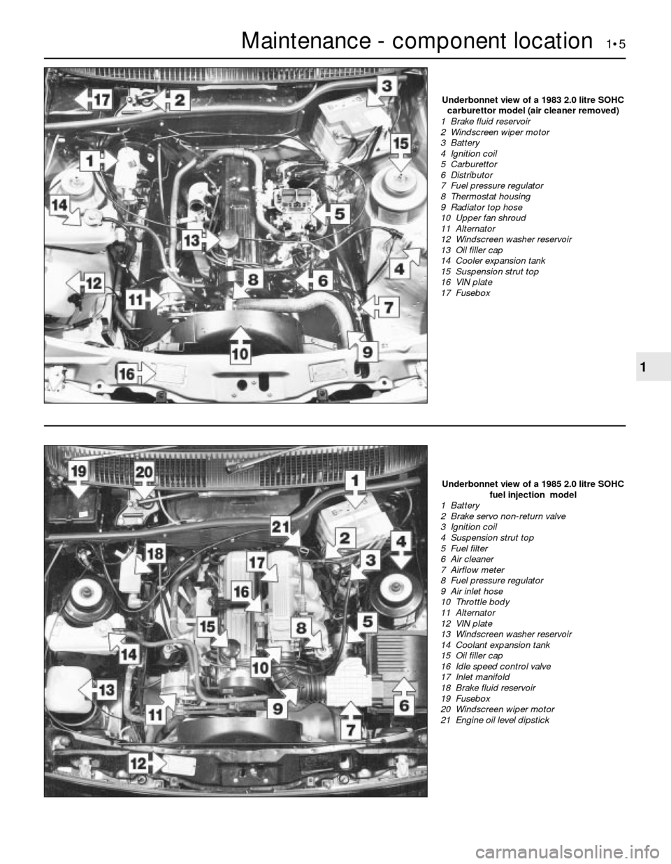
Maintenance - component location 1•5
1
Underbonnet view of a 1985 2.0 litre SOHC
fuel injection model
1 Battery
2 Brake servo non-return valve
3 Ignition coil
4 Suspension strut top
5 Fuel filter
6 Air cleaner
7 Airflow meter
8 Fuel pressure regulator
9 Air inlet hose
10 Throttle body
11 Alternator
12 VIN plate
13 Windscreen washer reservoir
14 Coolant expansion tank
15 Oil filler cap
16 Idle speed control valve
17 Inlet manifold
18 Brake fluid reservoir
19 Fusebox
20 Windscreen wiper motor
21 Engine oil level dipstick
Underbonnet view of a 1983 2.0 litre SOHC
carburettor model (air cleaner removed)
1 Brake fluid reservoir
2 Windscreen wiper motor
3 Battery
4 Ignition coil
5 Carburettor
6 Distributor
7 Fuel pressure regulator
8 Thermostat housing
9 Radiator top hose
10 Upper fan shroud
11 Alternator
12 Windscreen washer reservoir
13 Oil filler cap
14 Cooler expansion tank
15 Suspension strut top
16 VIN plate
17 Fusebox
Page 6 of 22
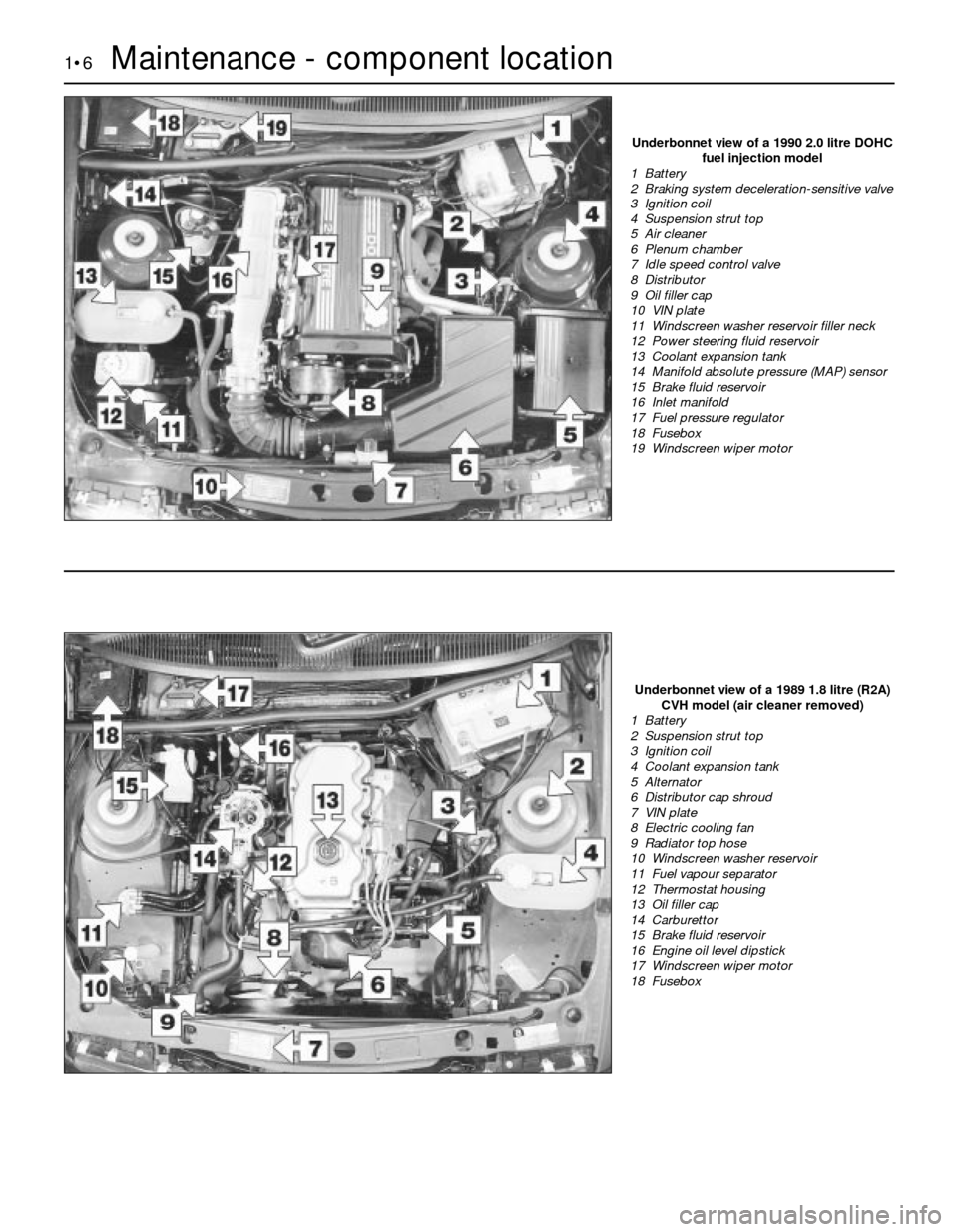
1•6Maintenance - component location
Underbonnet view of a 1990 2.0 litre DOHC
fuel injection model
1 Battery
2 Braking system deceleration-sensitive valve
3 Ignition coil
4 Suspension strut top
5 Air cleaner
6 Plenum chamber
7 Idle speed control valve
8 Distributor
9 Oil filler cap
10 VIN plate
11 Windscreen washer reservoir filler neck
12 Power steering fluid reservoir
13 Coolant expansion tank
14 Manifold absolute pressure (MAP) sensor
15 Brake fluid reservoir
16 Inlet manifold
17 Fuel pressure regulator
18 Fusebox
19 Windscreen wiper motor
Underbonnet view of a 1989 1.8 litre (R2A)
CVH model (air cleaner removed)
1 Battery
2 Suspension strut top
3 Ignition coil
4 Coolant expansion tank
5 Alternator
6 Distributor cap shroud
7 VIN plate
8 Electric cooling fan
9 Radiator top hose
10 Windscreen washer reservoir
11 Fuel vapour separator
12 Thermostat housing
13 Oil filler cap
14 Carburettor
15 Brake fluid reservoir
16 Engine oil level dipstick
17 Windscreen wiper motor
18 Fusebox
Page 7 of 22
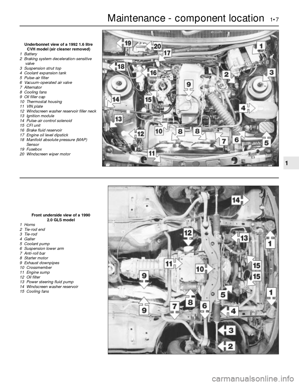
Maintenance - component location 1•7
1
Front underside view of a 1990
2.0 GLS model
1 Horns
2 Tie-rod end
3 Tie-rod
4 Gaiter
5 Coolant pump
6 Suspension lower arm
7 Anti-roll bar
8 Starter motor
9 Exhaust downpipes
10 Crossmember
11 Engine sump
12 Oil filter
13 Power steering fluid pump
14 Windscreen washer reservoir
15 Cooling fans
Underbonnet view of a 1992 1.6 litre
CVH model (air cleaner removed)
1 Battery
2 Braking system deceleration-sensitive
valve
3 Suspension strut top
4 Coolant expansion tank
5 Pulse-air filter
6 Vacuum-operated air valve
7 Alternator
8 Cooling fans
9 Oil filler cap
10 Thermostat housing
11 VIN plate
12 Windscreen washer reservoir filler neck
13 Ignition module
14 Pulse-air control solenoid
15 CFI unit
16 Brake fluid reservoir
17 Engine oil level dipstick
18 Manifold absolute pressure (MAP)
Sensor
19 Fusebox
20 Windscreen wiper motor
Page 14 of 22
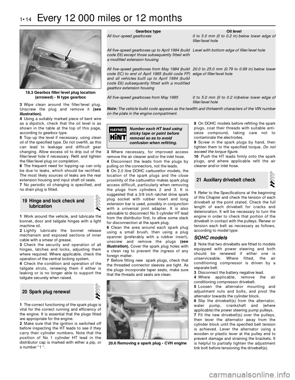
3Wipe clean around the filler/level plug.
Unscrew the plug and remove it(see
illustration).
4Using a suitably marked piece of bent wire
as a dipstick, check that the oil level is as
shown in the table at the top of this page,
according to gearbox type.
5Top-up the level if necessary, using clean
oil of the specified type. Do not overfill, as this
can lead to leakage and difficult gear
changing. Allow excess oil to drip out of the
filler/level hole if necessary. Refit and tighten
the filler/level plug on completion.
6The frequent need for topping-up can only
be due to leaks, which should be rectified.
The most likely sources of leaks are the rear
extension housing and input shaft oil seals.
7No periodic oil changing is specified, and
no drain plug is fitted.
1Work around the vehicle, and lubricate the
bonnet, door and tailgate hinges with a light
machine oil.
2Lightly lubricate the bonnet release
mechanism and exposed sections of inner
cable with a smear of grease.
3Check the security and operation of all
hinges, latches and locks, adjusting them
where required. Where applicable, check the
operation of the central locking system.
4Check the condition and operation of the
tailgate struts, renewing them if either is
leaking or is no longer able to support the
tailgate securely when raised.
1The correct functioning of the spark plugs is
vital for the correct running and efficiency of
the engine. It is essential that the plugs fitted
are appropriate for the engine.
2Make sure that the ignition is switched off
before inspecting the HT leads to see if they
carry their cylinder numbers. Note that the
position of No 1 cylinder HT lead in the
distributor cap is marked with either a pip, or
a number “1 “.3Where necessary, for improved access
remove the air cleaner and/or the inlet hose.
4Disconnect the leads from the plugs by
pulling on the connectors, not the leads.
5On 2.0 litre DOHC carburettor models, the
location of the spark plugs and the close
proximity of the carburettor makes spark plug
access difficult, particularly when removing
the plugs from cylinders 2 and 3. It is
suggested that a 3/8 inch ratchet drive spark
plug socket with rubber insert and long
extension bar is used, possibly in conjunction
with a universal joint adapter. It is also
advisable to disconnect No 3 cylinder HT lead
from the distributor first, to allow some slack
for disconnection at the spark plug.
6Clean the area around each spark plug
using a small brush, then using a plug
spanner (preferably with a rubber insert),
unscrew and remove the plugs(see
illustration).Cover the spark plug holes with
a clean rag to prevent the ingress of any
foreign matter.
7Before fitting new spark plugs, check that
the threaded connector sleeves are tight. As
the plugs incorporate taper seats, make sure
that the threads and seats are clean.8On DOHC models before refitting the spark
plugs, coat their threads with suitable anti-
seize compound, taking care not to
contaminate the electrodes.
9Screw in the spark plugs by hand, then
tighten them to the specified torque. Do not
exceed the torque figure.
10Push the HT leads firmly onto the spark
plugs, and where applicable refit the air
cleaner and/or inlet hose.
1Refer to the Specifications at the beginning
of this Chapter and check the tension of each
drivebelt at the point stated. Check the full
length of each drivebelt for cracks and
deterioration. It will be necessary to turn the
engine in order to check that portion of the
drivebelt in contact with the pulleys. Renew or
tension each belt as necessary as follows,
according to model type:
SOHC models
2Note that two drivebelts are fitted to models
equipped with power steering and both
should be renewed if either one is
unserviceable. Where fitted, the air
conditioning compressor is driven by a
separate belt.
3Disconnect the battery negative lead.
4Where applicable, remove the air
conditioning compressor drivebelt.
5Loosen the alternator mounting and
adjustment nuts and bolts, and pivot the
alternator towards the cylinder block.
6Slip the drivebelt(s) from the alternator,
water pump, crankshaft and (where
applicable) the power steering pump pulleys.
7Fit the new drivebelt(s) over the pulleys,
then lever the alternator away from the
cylinder block until the specified belt tension
is achieved. Lever the alternator using a
wooden or plastic lever at the pulley end to
prevent damage and straining the brackets. It
is helpful to partially tighten the adjustment
link bolt before tensioning the drivebelt(s).
21Auxiliary drivebelt check
20Spark plug renewal
19Hinge and lock check and
lubrication
1•14Every 12 000 miles or 12 months
18.3 Gearbox filler/level plug location
(arrowed) - N type gearbox
20.6 Removing a spark plug - CVH engine
Note: The vehicle build code appears as the twelfth and thirteenth characters of the VIN number
on the plate in the engine compartment.
Gearbox type
All four-speed gearboxes
All five-speed gearboxes up to April 1984 (build
code E6) except those subsequently fitted with
a modified extension housing
All five-speed gearboxes from May 1984 (build
code EC) to end of April 1985 (build code FP)
and all vehicles built up to April 1984 (build
code E6) subsequently fitted with a modified
gearbox extension housing
All five-speed gearboxes from May 1985Oil level
0 to 5.0 mm (0 to 0.2 in) below lower edge of
filler/level hole
Level with bottom edge of filler/level hole
20.0 to 25.0 mm (0.79 to 0.99 in) below lower
edge of filler/level hole
0 to 5.0 mm (0 to 0.2 in)below lower edge of
filler/level hole
Number each HT lead using
sticky tape or paint before
removal so as to avoid
confusion when refitting.
Page 15 of 22
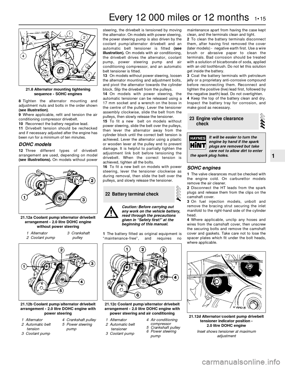
8Tighten the alternator mounting and
adjustment nuts and bolts in the order shown
(see illustration).
9Where applicable, refit and tension the air
conditioning compressor drivebelt.
10Reconnect the battery negative lead.
11Drivebelt tension should be rechecked
and if necessary adjusted after the engine has
been run for a minimum of ten minutes.
DOHC models
12Three different types of drivebelt
arrangement are used, depending on model
(see illustrations).On models without powersteering, the drivebelt is tensioned by moving
the alternator. On models with power steering,
the power steering pump is also driven by the
coolant pump/alternator drivebelt and an
automatic belt tensioner is fitted (see
illustration).On models with air conditioning,
the drivebelt drives the alternator, coolant
pump, power steering pump and air
conditioning compressor, and an automatic
belt tensioner is fitted.
13On models without power steering, loosen
the alternator mounting and adjustment bolts,
and pivot the alternator towards the cylinder
block. Slip the drivebelt from the pulleys.
14On models with power steering, the
automatic tensioner can be released using a
17 mm socket and a wrench on the boss in
the centre of the pulley. Lever the tensioner
assembly clockwise, slide the belt from the
pulleys, then slowly release the tensioner.
15To fit a new belt on models without
power steering, slide the belt over the pulleys,
then lever the alternator away from the
cylinder block until the correct belt tension is
achieved. Lever the alternator using a plastic
or wooden lever at the pulley end to prevent
damage. It is helpful to partially tighten the
adjustment link bolt before tensioning the
drivebelt. When the correct tension is
achieved, tighten all the bolts.
16To fit a new belt on models with power
steering, lever the tensioner clockwise as
during removal, then slide the belt over the
pulleys, and slowly release the tensioner.
1The battery fitted as original equipment is
“maintenance-free”, and requires nomaintenance apart from having the case kept
clean, and the terminals clean and tight.
2To clean the battery terminals disconnect
them, after having first removed the cover
(later models) - negative earth first. Use a wire
brush or abrasive paper to clean the
terminals. Bad corrosion should be treated
with a solution of bicarbonate of soda, applied
with an old toothbrush. Do not let this solution
get inside the battery.
3Coat the battery terminals with petroleum
jelly or a proprietary anti-corrosive compound
before reconnecting them. Reconnect and
tighten the positive (live) lead first, followed by
the negative (earth) lead. Do not overtighten.
4Keep the top of the battery clean and dry.
Inspect the battery tray for corrosion, and
make good as necessary.
SOHC engines
1The valve clearances must be checked with
the engine cold. On carburettor models
remove the air cleaner.
2Disconnect the HT leads from the spark
plugs and release them from the clips on the
camshaft cover.
3On fuel injection models, unbolt and
remove the bracing strut securing the inlet
manifold to the right-hand side of the cylinder
head.
4Where applicable, unclip any hoses and
wires from the camshaft cover, then unscrew
the securing bolts and remove the camshaft
cover and gaskets. Take care not to lose the
spacer plates which fit under the bolt heads,
where applicable.
23Engine valve clearance
check
22Battery terminal check
Every 12 000 miles or 12 months 1•15
1
21.12b Coolant pump/alternator drivebelt
arrangement - 2.0 litre DOHC engine with
power steering
1 Alternator
2 Automatic belt
tension
3 Coolant pump4 Crankshaft pulley
5 Power steering
pump21.12d Alternator/coolant pump drivebelt
tensioner indicator position -
2.0 litre DOHC engine
Inset shows tensioner at maximum
adjustment
1 Alternator
2 Automatic belt
tensioner
3 Coolant pump4 Air conditioning
compressor
5 Crankshaft pulley
6 Power steering
pump
21.12c Coolant pump/alternator drivebelt
arrangement - 2.0 litre DOHC engine with
power steering and air conditioning
21.12a Coolant pump/alternator drivebelt
arrangement - 2.0 litre DOHC engine
without power steering
1 Alternator
2 Coolant pump3 Crankshaft
pulley
21.8 Alternator mounting tightening
sequence - SOHC engines
Caution: Before carrying out
any work on the vehicle battery,
read through the precautions
given in “Safety first!” at the
beginning of this manual.
It will be easier to turn the
engine by hand if the spark
plugs are removed but take
care not to allow dirt to enter
the spark plug holes.