fuel injection FORD SIERRA 1993 2.G Engine Electrical Systems User Guide
[x] Cancel search | Manufacturer: FORD, Model Year: 1993, Model line: SIERRA, Model: FORD SIERRA 1993 2.GPages: 24, PDF Size: 0.93 MB
Page 24 of 24

Vehicle speed sensor
1.6 and 1.8 litre CVH (R6A type) and
2.0 litre DOHC fuel injection models
27The sensor is located in the left-hand side
of the gearbox/transmission.
28Disconnect the battery negative lead.
29Jack up the vehicle and support it
securely on axle stands (see “Jacking and
Vehicle Support”).
30Detach the sensor wiring connector from
its bracket, and separate the two halves of the
connector.
31Unscrew the securing bolt, and withdraw
the wiring connector bracket, noting its
orientation.
32Withdraw the sensor from the
gearbox/transmission casing (see
illustration).
33Before refitting the sensor, examine the
O-ring, and renew if damaged or worn.
34Refitting is a reversal of removal, ensuring
that the wiring connector bracket is correctly
located.
Manifold absolute pressure (MAP)
sensor
1.6 and 1.8 litre CVH (R6A type) and
2.0 litre DOHC fuel injection models
35The sensor is located at the rear right-
hand side of the engine compartment (see
illustration).
36Disconnect the battery negative lead.
37Remove the two screws securing the
sensor to the body panel, and carefully
withdraw the sensor, taking care not to strainthe wiring.
38Disconnect the wiring plug from the
sensor, pulling on the plug, not the wiring,
then disconnect the vacuum hose and remove
the sensor.
39Refitting is a reversal of removal.
Fuel temperature sensor -
removal and refitting
2.0 litre DOHC fuel injection models
40The sensor is located in the top of the fuel
rail.
41Disconnect the battery negative lead, and
to improve access, disconnect the wiring plug
from the air charge temperature sensor (in the
inlet manifold). Disconnect the sensor wiring
plug by pulling on the plug, not the wiring.
42Disconnect the fuel temperature sensor
wiring plug, again pulling on the plug (see
illustration).
43Unscrew the sensor from the fuel rail, and
remove it.
44Refitting is a reversal of removal, noting
the torque setting for the sensor.
Spark delay and sustain valves
1Disconnect the vacuum pipes at the valve
and withdraw the valve.
2When refitting a spark delay valve, the valve
must be positioned with the black end
(marked “CARB”) towards the carburettor and
the coloured end (marked “DIST”) towards the
distributor or electronic module (as
applicable).
3When refitting a spark sustain valve, the
valve must be positioned with the end marked
“VAC” towards the carburettor and the side
marked “DIST” towards the distributor or
electronic module (as applicable).
Ported vacuum switch
4Where fitted, the switch(es) may be located
in the inlet manifold and/or in an adapter fitted
in one of the coolant hoses.
5To remove a switch, partially drain the
cooling system. Note that there is no need to
remove the cylinder block drain plug.
6Mark the vacuum pipes for location so that
they can be refitted in their correct positions,
then disconnect the pipes from the switch.
7Unscrew the valve from its location.
8Refitting is a reversal of removal, ensuring
that the vacuum pipes are correctly
connected. Refill the cooling system.
Fuel trap
9Disconnect the vacuum pipes at the fuel
trap and withdraw the fuel trap.
10When refitting, the fuel trap must be
positioned with the black end (marked
“CARB”) towards the carburettor, and the
white side (marked “DIST”) towards the
distributor, electronic module, or ported
vacuum switch (as applicable) (see
illustration).
Spark control system additional
components
11According to model, engine and
equipment, additional components such as
one-way valves or solenoids may also be
fitted as part of the spark control system.
12The removal and refitting procedures for
these components are basically as described
previously, and provided that all attachments
are marked for position prior to removal, no
problems should be encountered.
22Spark control system
components (carburettor
models) - removal and refitting
5•24Engine electrical systems
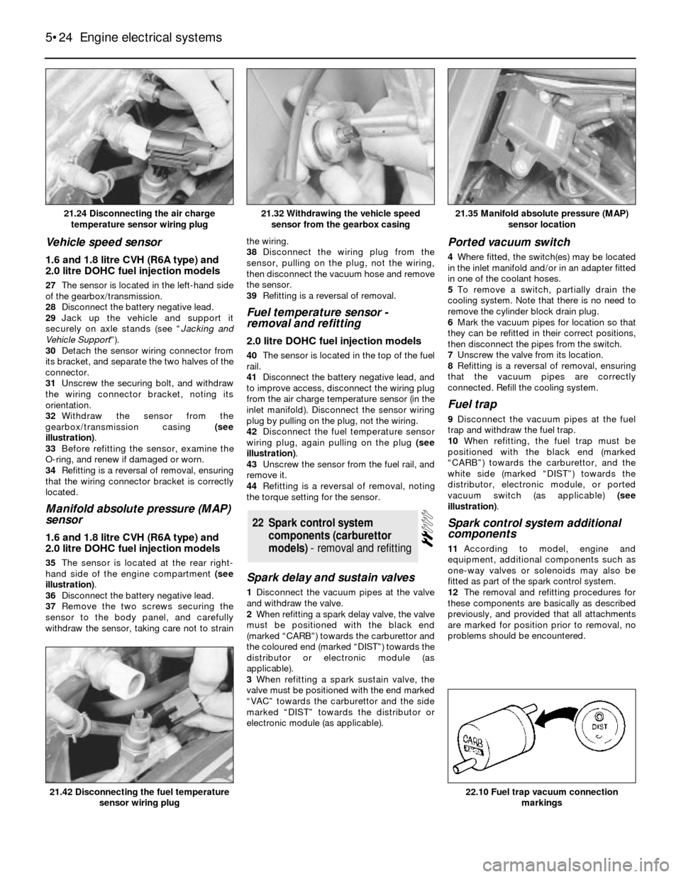
21.24 Disconnecting the air charge
temperature sensor wiring plug21.35 Manifold absolute pressure (MAP)
sensor location
22.10 Fuel trap vacuum connection
markings21.42 Disconnecting the fuel temperature
sensor wiring plug
21.32 Withdrawing the vehicle speed
sensor from the gearbox casing