brake FORD SUPER DUTY 2004 1.G Service Manual
[x] Cancel search | Manufacturer: FORD, Model Year: 2004, Model line: SUPER DUTY, Model: FORD SUPER DUTY 2004 1.GPages: 304, PDF Size: 3.96 MB
Page 184 of 304
Preparing to tow
Use the proper equipment for towing a trailer and make sure it is
properly attached to your vehicle. See your dealer or a reliable trailer
dealer if you require assistance.
Hitches
Do not use hitches that clamp onto the vehicle’s bumper or attach to the
axle. You must distribute the load in your trailer so that 10%–15% of the
total weight of the trailer is on the tongue.
Load equalizing hitch
When hooking up a trailer using a load equalizing hitch, always use the
following procedure:
1. Park the unloaded vehicle on a level surface. With the ignition on and
all doors closed, allow the vehicle to stand for several minutes so that it
can level.
2. Measure the height of a reference point on the front and rear bumpers
at the center of the vehicle.
3. Attach the trailer to the vehicle and adjust the hitch equalizers so that
the front bumper height is within 0–13 mm (0.5 in) of the reference
point. After proper adjustment, the rear bumper should be no higher
than in Step 2.
Note:Adjusting an equalizing hitch so the rear bumper of the vehicle is
higher than it was unloaded will defeat the function of the load
equalizing hitch and may cause unpredictable handling.
Safety chains
Always connect the trailer’s safety chains to the frame or hook retainers
of the vehicle hitch. To connect the trailer’s safety chains, cross the
chains under the trailer tongue and allow slack for turning corners.
If you use a rental trailer, follow the instructions that the rental agency
gives to you.
Do not attach safety chains to the bumper.
Trailer brakes
Electric brakes and manual, automatic or surge-type trailer brakes are
safe if installed properly and adjusted to the manufacturer’s
specifications. The trailer brakes must meet local and Federal
regulations.
2004 F250/350/450/550(f23)
Owners Guide (post-2002-fmt)
USA English(fus)
Driving
184
Page 185 of 304
Do not connect a trailer’s hydraulic brake system directly to your
vehicle’s brake system. Your vehicle may not have enough
braking power and your chances of having a collision greatly increase.
The braking system of the tow vehicle is rated for operation at the
GVWR not GCWR.
Trailer lamps
Trailer lamps are required on most towed vehicles. Make sure all running
lights, brake lights, turn signals and hazard lights are working. See your
dealer or trailer rental agency for proper instructions and equipment for
hooking up trailer lamps.
Using a step bumper (if equipped)
The rear bumper is equipped with an integral hitch and only requires a
ball with a 25.4 mm (one inch) shank diameter. The bumper has a 2,270
kg (5,000 lb.) trailer weight and 227 kg (500 lb.) tongue weight capacity.
If it is necessary to relocate the trailer hitch ball position, a
frame-mounted trailer hitch must be installed.
Driving while you tow
When towing a trailer:
•Turn off the speed control. The speed control may shut off
automatically when you are towing on long, steep grades.
•Consult your local motor vehicle speed regulations for towing a trailer.
•If your vehicle is equipped with a 4–speed automatic
transmission:To eliminate excessive transmission shifting, use a
lower gear. This will also assist in transmission cooling. (For additional
information, refer to theUnderstanding the positions of the 4–speed
automatic transmissionsection in this chapter.
•If your vehicle is equipped with a 5–speed automatic
transmission:To eliminate excessive transmission shifting, activate
the Tow/Haul feature. This will also assist in transmission cooling. (For
additional information, refer to theUnderstanding the positions of
the 5–speed automatic transmissionsection in this chapter.
•Anticipate stops and brake gradually.
•Do not exceed the GCWR rating or transmission damage may occur.
2004 F250/350/450/550(f23)
Owners Guide (post-2002-fmt)
USA English(fus)
Driving
185
Page 194 of 304
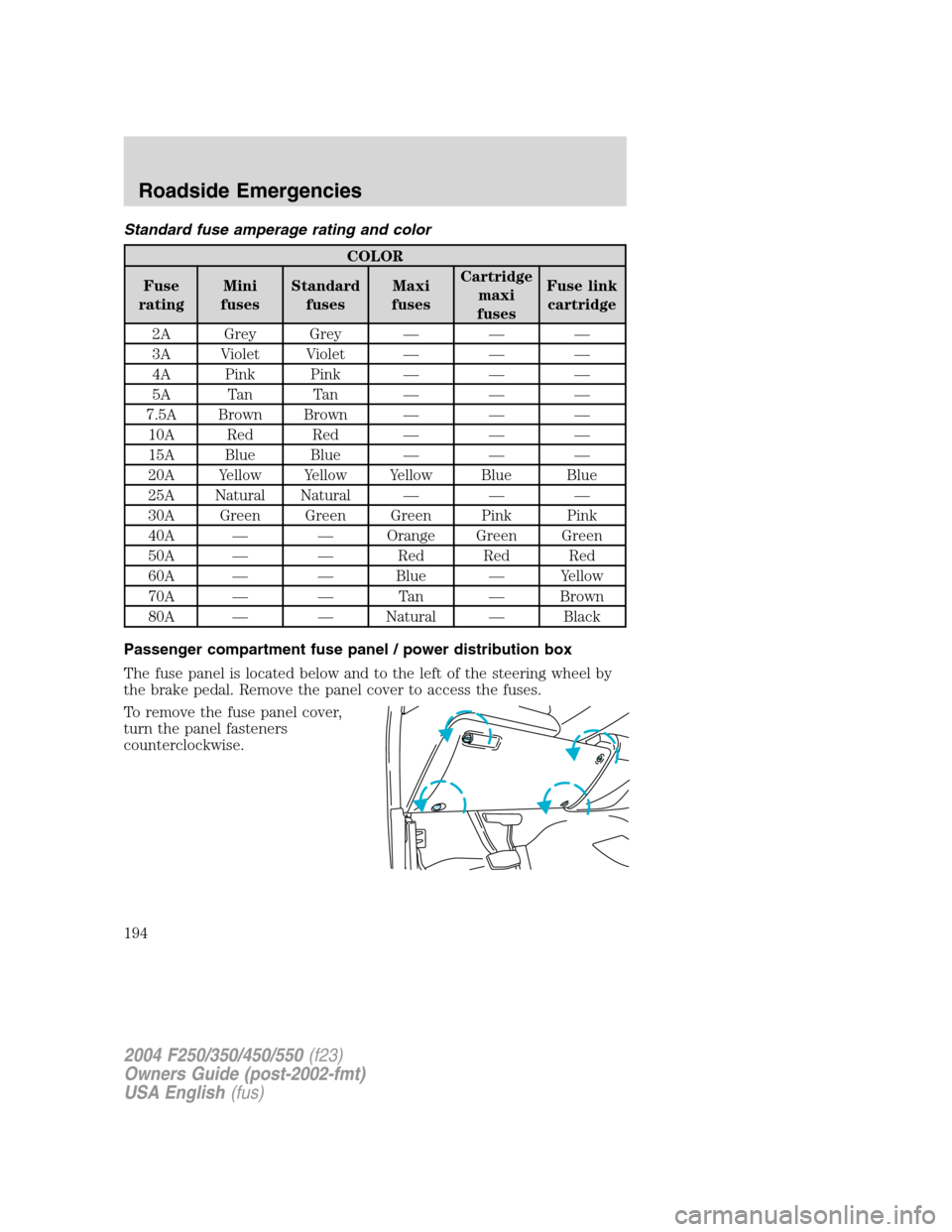
Standard fuse amperage rating and color
COLOR
Fuse
ratingMini
fusesStandard
fusesMaxi
fusesCartridge
maxi
fusesFuse link
cartridge
2A Grey Grey———
3A Violet Violet———
4A Pink Pink———
5A Tan Tan———
7.5A Brown Brown———
10A Red Red———
15A Blue Blue———
20A Yellow Yellow Yellow Blue Blue
25A Natural Natural———
30A Green Green Green Pink Pink
40A——Orange Green Green
50A——Red Red Red
60A——Blue—Yellow
70A——Ta n—Brown
80A——Natural—Black
Passenger compartment fuse panel / power distribution box
The fuse panel is located below and to the left of the steering wheel by
the brake pedal. Remove the panel cover to access the fuses.
To remove the fuse panel cover,
turn the panel fasteners
counterclockwise.
2004 F250/350/450/550(f23)
Owners Guide (post-2002-fmt)
USA English(fus)
Roadside Emergencies
194
Page 196 of 304
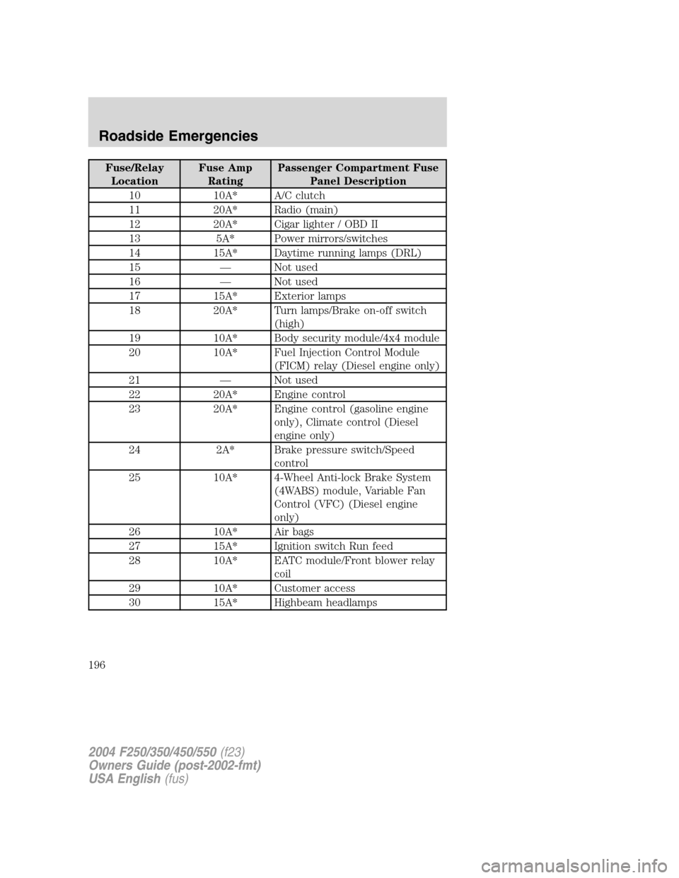
Fuse/Relay
LocationFuse Amp
RatingPassenger Compartment Fuse
Panel Description
10 10A* A/C clutch
11 20A* Radio (main)
12 20A* Cigar lighter / OBD II
13 5A* Power mirrors/switches
14 15A* Daytime running lamps (DRL)
15—Not used
16—Not used
17 15A* Exterior lamps
18 20A* Turn lamps/Brake on-off switch
(high)
19 10A* Body security module/4x4 module
20 10A* Fuel Injection Control Module
(FICM) relay (Diesel engine only)
21—Not used
22 20A* Engine control
23 20A* Engine control (gasoline engine
only), Climate control (Diesel
engine only)
24 2A* Brake pressure switch/Speed
control
25 10A* 4-Wheel Anti-lock Brake System
(4WABS) module, Variable Fan
Control (VFC) (Diesel engine
only)
26 10A* Air bags
27 15A* Ignition switch Run feed
28 10A* EATC module/Front blower relay
coil
29 10A* Customer access
30 15A* Highbeam headlamps
2004 F250/350/450/550(f23)
Owners Guide (post-2002-fmt)
USA English(fus)
Roadside Emergencies
196
Page 197 of 304
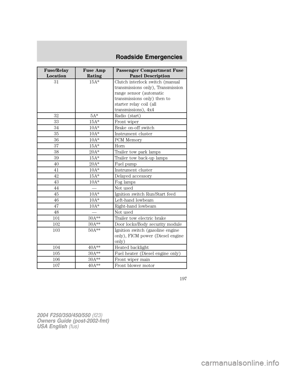
Fuse/Relay
LocationFuse Amp
RatingPassenger Compartment Fuse
Panel Description
31 15A* Clutch interlock switch (manual
transmissions only), Transmission
range sensor (automatic
transmissions only) then to
starter relay coil (all
transmissions), 4x4
32 5A* Radio (start)
33 15A* Front wiper
34 10A* Brake on-off switch
35 10A* Instrument cluster
36 10A* PCM Memory
37 15A* Horn
38 20A* Trailer tow park lamps
39 15A* Trailer tow back-up lamps
40 20A* Fuel pump
41 10A* Instrument cluster
42 15A* Delayed accessory
43 10A* Fog lamps
44—Not used
45 10A* Ignition switch Run/Start feed
46 10A* Left-hand lowbeam
47 10A* Right-hand lowbeam
48—Not used
101 30A** Trailer tow electric brake
102 30A** Door locks/Body security module
103 50A** Ignition switch (gasoline engine
only), FICM power (Diesel engine
only)
104 40A** Heated backlight
105 30A** Fuel heater (Diesel engine only)
106 30A** Front wiper main
107 40A** Front blower motor
2004 F250/350/450/550(f23)
Owners Guide (post-2002-fmt)
USA English(fus)
Roadside Emergencies
197
Page 198 of 304
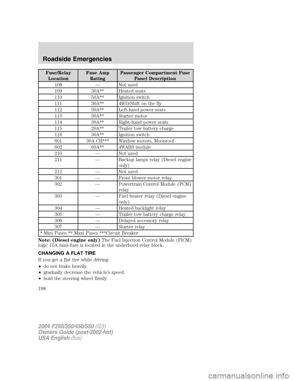
Fuse/Relay
LocationFuse Amp
RatingPassenger Compartment Fuse
Panel Description
108—Not used
109 30A** Heated seats
110 50A** Ignition switch
111 30A** 4WD/Shift on the fly
112 30A** Left-hand power seats
113 30A** Starter motor
114 30A** Right-hand power seats
115 20A** Trailer tow battery charge
116 30A** Ignition switch
601 30A CB*** Window motors, Moonroof
602 60A** 4WABS module
210—Not used
211—Backup lamps relay (Diesel engine
only)
212—Not used
301—Front blower motor relay
302—Powertrain Control Module (PCM)
relay
303—Fuel heater relay (Diesel engine
only)
304—Heated backlight relay
305—Trailer tow battery charge relay
306—Delayed accessory relay
307—Starter relay
* Mini Fuses ** Maxi Fuses ***Circuit Breaker
Note: (Diesel engine only)The Fuel Injection Control Module (FICM)
logic 15A mini-fuse is located in the underhood relay block.
CHANGING A FLAT TIRE
If you get a flat tire while driving:
•do not brake heavily.
•gradually decrease the vehicle’s speed.
•hold the steering wheel firmly.
2004 F250/350/450/550(f23)
Owners Guide (post-2002-fmt)
USA English(fus)
Roadside Emergencies
198
Page 201 of 304
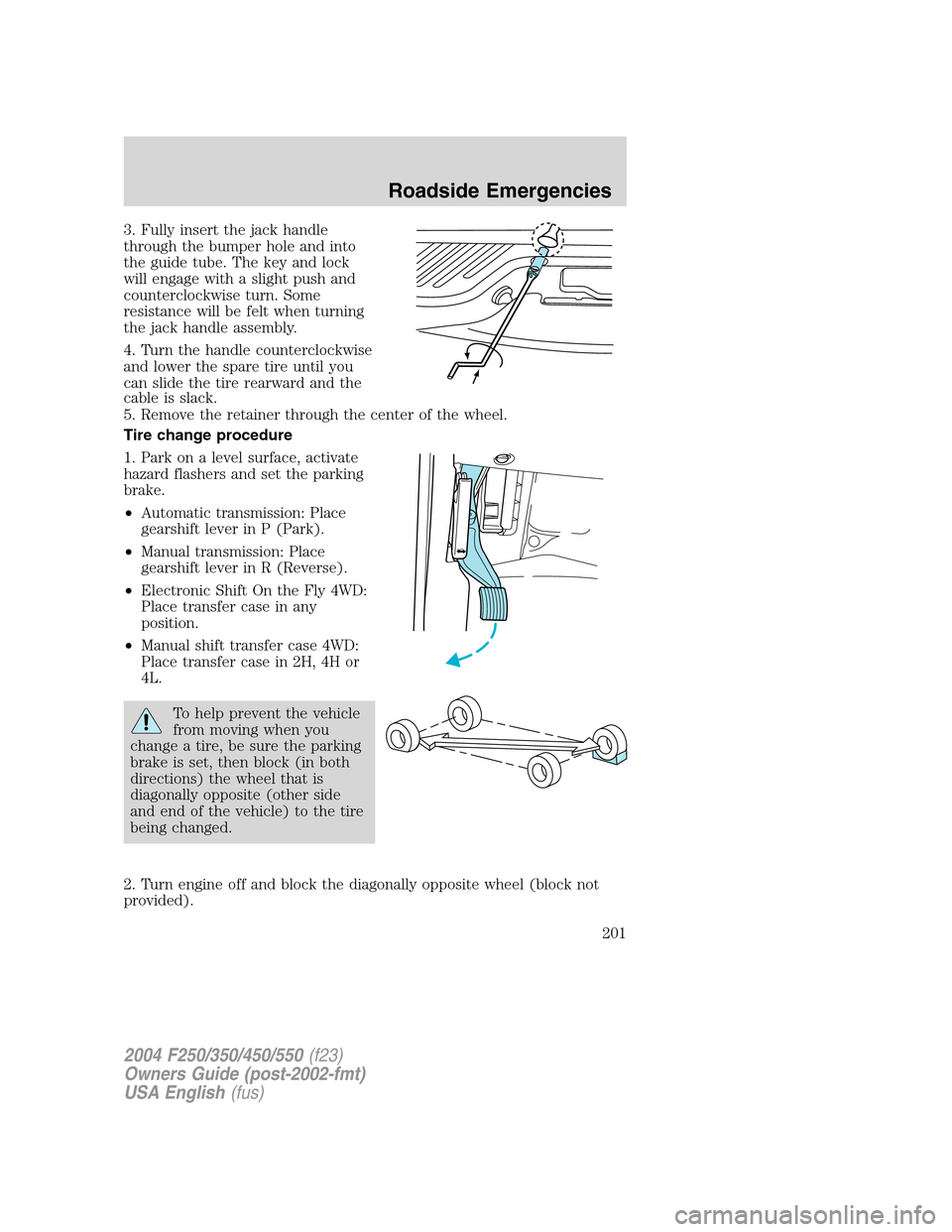
3. Fully insert the jack handle
through the bumper hole and into
the guide tube. The key and lock
will engage with a slight push and
counterclockwise turn. Some
resistance will be felt when turning
the jack handle assembly.
4. Turn the handle counterclockwise
and lower the spare tire until you
can slide the tire rearward and the
cable is slack.
5. Remove the retainer through the center of the wheel.
Tire change procedure
1. Park on a level surface, activate
hazard flashers and set the parking
brake.
•Automatic transmission: Place
gearshift lever in P (Park).
•Manual transmission: Place
gearshift lever in R (Reverse).
•Electronic Shift On the Fly 4WD:
Place transfer case in any
position.
•Manual shift transfer case 4WD:
Place transfer case in 2H, 4H or
4L.
To help prevent the vehicle
from moving when you
change a tire, be sure the parking
brake is set, then block (in both
directions) the wheel that is
diagonally opposite (other side
and end of the vehicle) to the tire
being changed.
2. Turn engine off and block the diagonally opposite wheel (block not
provided).
2004 F250/350/450/550(f23)
Owners Guide (post-2002-fmt)
USA English(fus)
Roadside Emergencies
201
Page 202 of 304
3. Remove the jack, jack handle, lug wrench and spare tire from the
stowage locations.
4. Use the tip of the lug wrench to remove any wheel trim.
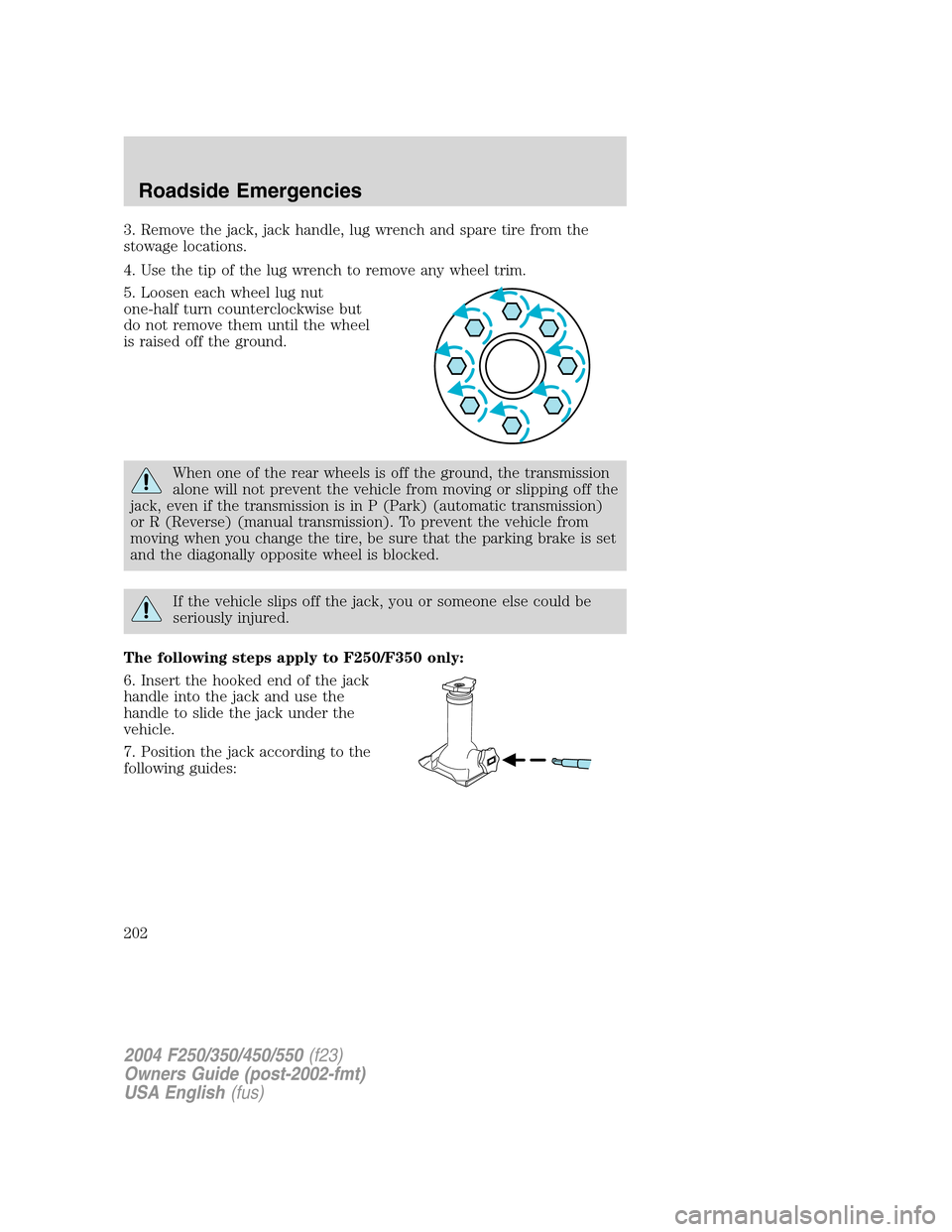
5. Loosen each wheel lug nut
one-half turn counterclockwise but
do not remove them until the wheel
is raised off the ground.
When one of the rear wheels is off the ground, the transmission
alone will not prevent the vehicle from moving or slipping off the
jack, even if the transmission is in P (Park) (automatic transmission)
or R (Reverse) (manual transmission). To prevent the vehicle from
moving when you change the tire, be sure that the parking brake is set
and the diagonally opposite wheel is blocked.
If the vehicle slips off the jack, you or someone else could be
seriously injured.
The following steps apply to F250/F350 only:
6. Insert the hooked end of the jack
handle into the jack and use the
handle to slide the jack under the
vehicle.
7. Position the jack according to the
following guides:
2004 F250/350/450/550(f23)
Owners Guide (post-2002-fmt)
USA English(fus)
Roadside Emergencies
202
Page 209 of 304
When a wheel is installed, always remove any corrosion, dirt or
foreign materials present on the mounting surfaces of the wheel
or the surface of the front disc brake hub and rotor that contacts the
wheel. Installing wheels without correct metal-to-metal contact at the
wheel mounting surfaces can cause the wheel nuts to loosen and the
wheel to come off while the vehicle is in motion, resulting in loss of
control.
JUMP STARTING YOUR VEHICLE
The gases around the battery can explode if exposed to flames,
sparks, or lit cigarettes. An explosion could result in injury or
vehicle damage.
Batteries contain sulfuric acid which can burn skin, eyes and
clothing, if contacted.
Do not attempt to push-start your vehicle. Automatic
transmissions do not have push-start capability; doing so may
damage the catalytic converter.
Preparing your vehicle
When the battery is disconnected or a new battery is installed, the
transmission must relearn its shift strategy. As a result, the transmission
may have firm and/or soft shifts. This operation is considered normal and
will not affect function or durability of the transmission. Over time, the
adaptive learning process will fully update transmission operation.
1.Use only a 12–volt supply to start your vehicle.
2. Do not disconnect the battery of the disabled vehicle as this could
damage the vehicle’s electrical system.
3. Park the booster vehicle close to the hood of the disabled vehicle
making sure the two vehiclesdo nottouch. Set the parking brake on
both vehicles and stay clear of the engine cooling fan and other moving
parts.
4. Check all battery terminals and remove any excessive corrosion before
you attach the battery cables. Ensure that vent caps are tight and level.
5. Turn the heater fan on in both vehicles to protect any electrical
surges. Turn all other accessories off.
2004 F250/350/450/550(f23)
Owners Guide (post-2002-fmt)
USA English(fus)
Roadside Emergencies
209
Page 226 of 304
PAINT CHIPS
Your dealer has touch-up paint and sprays to match your vehicle’s color.
Take your color code (printed on a sticker in the driver’s door jam) to
your dealer to ensure you get the correct color.
•Remove particles such as bird droppings, tree sap, insect deposits, tar
spots, road salt and industrial fallout before repairing paint chips.
•Always read the instructions before using the products.
ALUMINUM WHEELS AND WHEEL COVERS
Aluminum wheels and wheel covers are coated with a clearcoat paint
finish. In order to maintain their shine:
•Clean weekly with Motorcraft Wheel and Tire Cleaner (ZC-37–A),
which is available from your dealer. Heavy dirt and brake dust
accumulation may require agitation with a sponge. Rinse thoroughly
with a strong stream of water.
•Never apply any cleaning chemical to hot or warm wheel rims or
covers.
•Some automatic car washes may cause damage to the finish on your
wheel rims or covers. Chemical-strength cleaners, or cleaning
chemicals, in combination with brush agitation to remove brake dust
and dirt, could wear away the clearcoat finish over time.
•Do not use hydrofluoric acid-based or high caustic-based wheel
cleaners, steel wool, fuels or strong household detergent.
•To remove tar and grease, use Motorcraft Bug and Tar Remover
(ZC-42), available from your dealer.
ENGINE
Engines are more efficient when they are clean because grease and dirt
buildup keep the engine warmer than normal. When washing:
•Take care when using a power washer to clean the engine. The
high-pressure fluid could penetrate the sealed parts and cause
damage.
•Do not spray a hot engine with cold water to avoid cracking the
engine block or other engine components.
•Spray Motorcraft Engine Shampoo and Degreaser (ZC-20) on all parts
that require cleaning and pressure rinse clean.
•Never wash or rinse the engine while it is running; water in the
running engine may cause internal damage.
2004 F250/350/450/550(f23)
Owners Guide (post-2002-fmt)
USA English(fus)
Cleaning
226