battery FORD SUPER DUTY 2008 2.G Diesel Supplement Manual
[x] Cancel search | Manufacturer: FORD, Model Year: 2008, Model line: SUPER DUTY, Model: FORD SUPER DUTY 2008 2.GPages: 96, PDF Size: 0.64 MB
Page 19 of 96
JUMP STARTING YOUR VEHICLE (E-SERIES ONLY)
The following procedure is for E-Series vehicles only. F-Super
Duty vehicles equipped with the 6.4L diesel engine can be jump
started using the same procedure as a gasoline engine; refer to
yourOwner’s Guidefor the jump starting procedure.
The gases around the battery can explode if exposed to flames,
sparks, or lit cigarettes. An explosion could result in injury or
vehicle damage.
Batteries contain sulfuric acid which can burn skin, eyes and
clothing, if contacted.
Do not attempt to push-start your vehicle. Automatic
transmissions do not have push-start capability; damage to the
automatic transmission may result.
Preparing your vehicle
When the batteries are disconnected or new batteries are installed, the
transmission must relearn its shift strategy. As a result, the transmission
may have firm and/or soft shifts. This operation is considered normal and
will not affect function or durability of the transmission. Over time, the
adaptive learning process will fully update transmission operation
1.Use only a 12–volt supply to start your vehicle.
2. Do not disconnect the batteries of the disabled vehicle as this could
damage the vehicle’s electrical system.
3. Park the booster vehicle close to the passenger side of the disabled
vehicle making sure the two vehiclesdo nottouch. Set the parking
brake on both vehicles.
Note:This vehicle has two frame-mounted batteries located on the
passenger side frame rail, behind the front passenger door. A battery
positive (+) jumper stud is located on the frame rail behind the rear
most battery box.
2008 Econoline(eco)
Supplement
USA(fus)
Roadside emergencies
19
Page 20 of 96
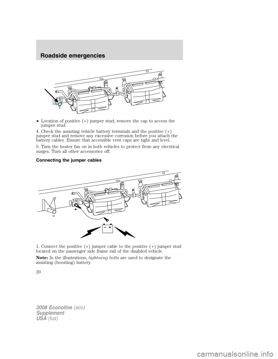
•Location of positive (+) jumper stud; remove the cap to access the
jumper stud.
4. Check the assisting vehicle battery terminals and the positive (+)
jumper stud and remove any excessive corrosion before you attach the
battery cables. Ensure that accessible vent caps are tight and level.
5. Turn the heater fan on in both vehicles to protect from any electrical
surges. Turn all other accessories off.
Connecting the jumper cables
1. Connect the positive (+) jumper cable to the positive (+) jumper stud
located on the passenger side frame rail of the disabled vehicle.
Note:In the illustrations,lightning boltsare used to designate the
assisting (boosting) battery.
2008 Econoline(eco)
Supplement
USA(fus)
Roadside emergencies
20
Page 21 of 96
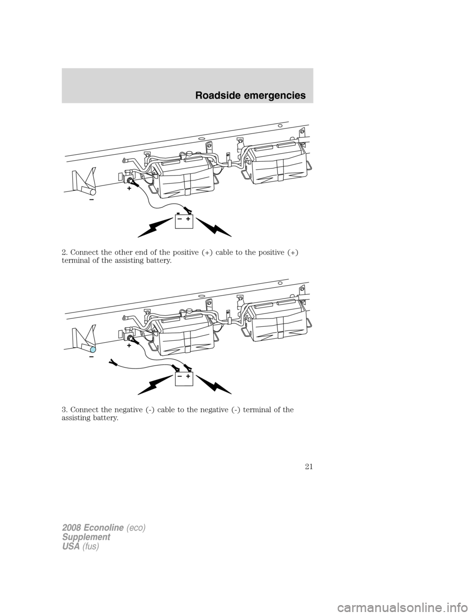
2. Connect the other end of the positive (+) cable to the positive (+)
terminal of the assisting battery.
3. Connect the negative (-) cable to the negative (-) terminal of the
assisting battery.
2008 Econoline(eco)
Supplement
USA(fus)
Roadside emergencies
21
Page 22 of 96
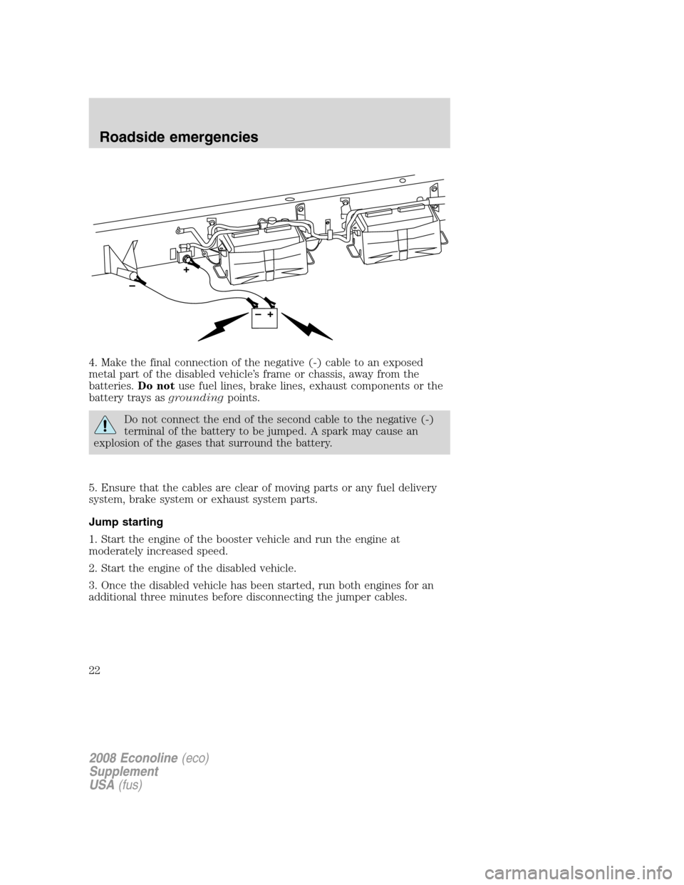
4. Make the final connection of the negative (-) cable to an exposed
metal part of the disabled vehicle’s frame or chassis, away from the
batteries.Do notuse fuel lines, brake lines, exhaust components or the
battery trays asgroundingpoints.
Do not connect the end of the second cable to the negative (-)
terminal of the battery to be jumped. A spark may cause an
explosion of the gases that surround the battery.
5. Ensure that the cables are clear of moving parts or any fuel delivery
system, brake system or exhaust system parts.
Jump starting
1. Start the engine of the booster vehicle and run the engine at
moderately increased speed.
2. Start the engine of the disabled vehicle.
3. Once the disabled vehicle has been started, run both engines for an
additional three minutes before disconnecting the jumper cables.
2008 Econoline(eco)
Supplement
USA(fus)
Roadside emergencies
22
Page 23 of 96
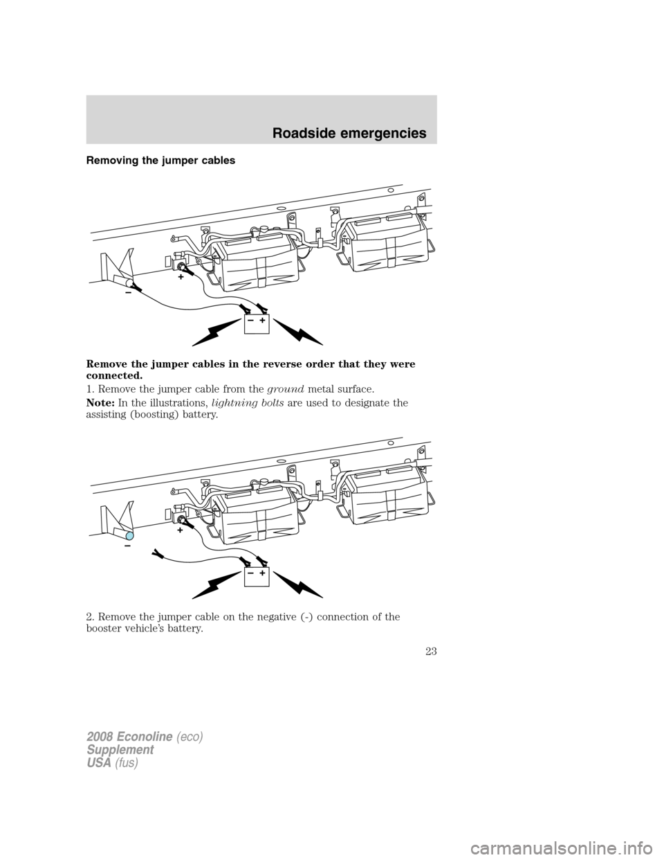
Removing the jumper cables
Remove the jumper cables in the reverse order that they were
connected.
1. Remove the jumper cable from thegroundmetal surface.
Note:In the illustrations,lightning boltsare used to designate the
assisting (boosting) battery.
2. Remove the jumper cable on the negative (-) connection of the
booster vehicle’s battery.
2008 Econoline(eco)
Supplement
USA(fus)
Roadside emergencies
23
Page 24 of 96
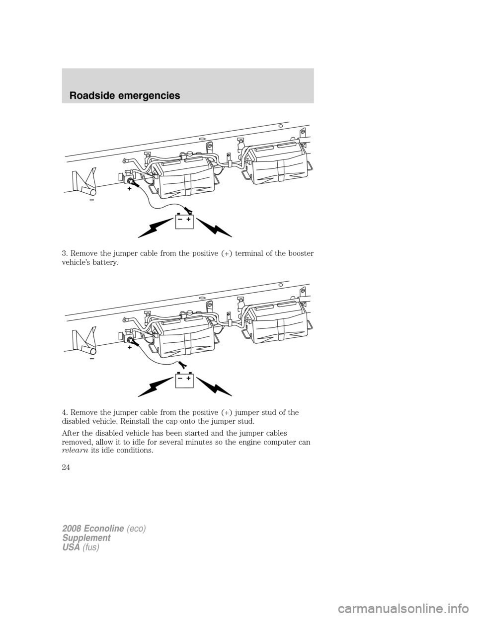
3. Remove the jumper cable from the positive (+) terminal of the booster
vehicle’s battery.
4. Remove the jumper cable from the positive (+) jumper stud of the
disabled vehicle. Reinstall the cap onto the jumper stud.
After the disabled vehicle has been started and the jumper cables
removed, allow it to idle for several minutes so the engine computer can
relearnits idle conditions.
2008 Econoline(eco)
Supplement
USA(fus)
Roadside emergencies
24
Page 51 of 96
MINOR TROUBLESHOOTING GUIDE
Air purge procedure
Turn the key on for 30 seconds, then turn off. Repeat procedure four or
five times.
If the engine won’t crank
Turn on the headlights. If the lights are dim, do not go on at all or when
the ignition is turned to START the lights become dim or go out, the
battery connections may be loose or corroded, or the battery may be
discharged. If there is a clicking or stuttering sound coming from the
engine compartment when you turn the key to START, this may also
indicate a loose or corroded battery connection.
Check the battery connections at the battery posts, cable connection to
the engine grounding point and at the starter connection.
If a discharged battery is suspected, have it checked and corrected.
Battery posts, terminals and related accessories contain lead and
lead compounds.Wash hands after handling.
•For vehicles with manual transmissions,the clutch pedalmustbe
fully depressed in order for the starter to operate.
•For vehicles with automatic transmissions,the gearshift lever
must be in P (Park) or N (Neutral) in order for the starter to operate.
•Try operating the starter switch several times. Should the switch be
corroded, this operation may clean the contacts or make the switch
temporarily operable until you can reach the dealer.
•If all electrical connections are tight and you need assistance to start,
refer toJump startingin theRoadside Emergencieschapter of your
Owner’s Guide(F-Super Duty) or refer to theJump startingsection
in theRoadside Emergencieschapter of this supplement (E-Series).
If engine cranks but won’t start
Prolonged starter cranking (in excess of 30 seconds) could cause
damage to the starter motor.
•Check the fuel gauge. You may be out of fuel. If the gauge shows that
there is fuel in the tank, the trouble may be in the electrical system or
the fuel system. If equipped with an auxiliary tank, be sure that the
tank control switch is set for the tank with fuel and not on an empty
tank.
2008 Econoline(eco)
Supplement
USA(fus)
Maintenance and Specifications
51
Page 53 of 96
MOTORCRAFT PART NUMBERS
Item Ford Part Number
Engine oil filter FL-2016
Air filter – E-Series* FA-1804
Air filter – F-Super Duty* FA-1886
Fuel filter (2 required) FD-4604
Battery (2 Required) BXT-65-750
* Always use the authorized Motorcraft air filter listed.Failure to use
the correct air filter may result in severe engine damage.
2008 Econoline(eco)
Supplement
USA(fus)
Maintenance and Specifications
53
Page 58 of 96
request your authorization to perform additional operations to determine
the final diagnosis. The technician’s goal is to ensure that your vehicle is
fixed right the first time, at the best value to you.
The following list represents several of the Factory Authorized Systems
Checks available at participating Ford or Lincoln Mercury dealers:
•Air Conditioning
•Check Engine Light
•All Wheel Drive and4X4
•Automatic Transmission
•Engine Cooling and Cabin Heating
•Steering and Suspension
•Charge/Start/Battery
•Wheel Alignment
•Anti-Lock Brake System
Genuine Ford and Motorcraft Replacement Parts
Ford and Lincoln Mercury dealerships stock Ford and Motorcraft
branded replacement parts. These parts meet or exceed Ford Motor
Company’s specifications, and we stand behind them. Maintenance parts
installed at your Ford or Lincoln Mercury dealership carry a nationwide,
12 months, 12,000 mile (20,000 km) parts and labor limited warranty.
Your dealer can give you details.
Value Shopping for Your Vehicle’s Maintenance Needs
Your dealership recognizes the competitive landscape of maintenance and
light repair automotive services. With factory-trained technicians, and
one-stop service from routine maintenance like oil changes and tire
rotations to repairs like brake service, check out the value your Ford and
Lincoln Mercury dealers can offer.
2008 Econoline(eco)
Supplement
USA(fus)
Scheduled Maintenance: General Information
58
Page 60 of 96
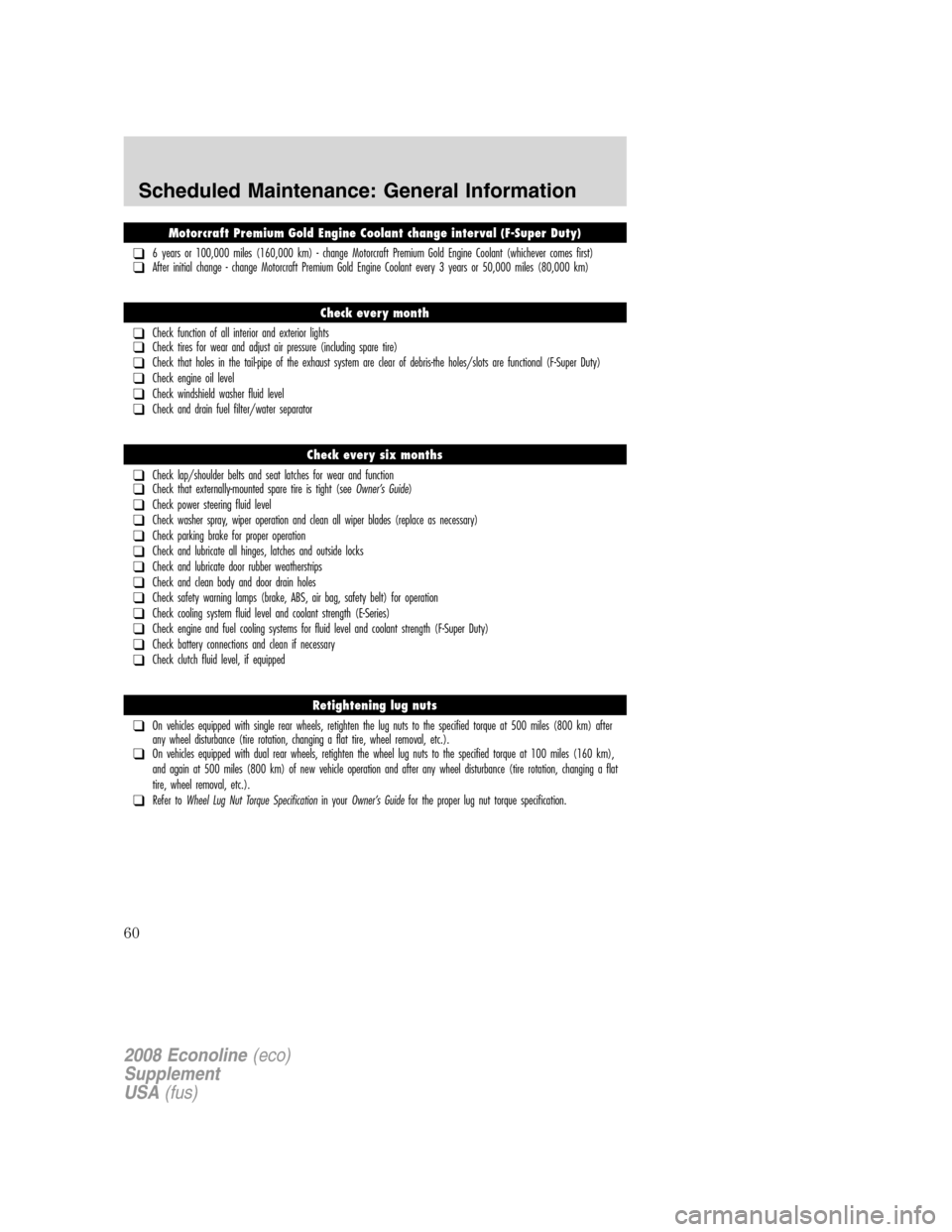
Motorcraft Premium Gold Engine Coolant change interval (F-Super Duty)
❑6 years or 100,000 miles (160,000 km) - change Motorcraft Premium Gold Engine Coolant (whichever comes first)❑After initial change - change Motorcraft Premium Gold Engine Coolant every 3 years or 50,000 miles (80,000 km)
Check every month
❑Check function of all interior and exterior lights❑Check tires for wear and adjust air pressure (including spare tire)
❑Check that holes in the tail-pipe of the exhaust system are clear of debris-the holes/slots are functional (F-Super Duty)
❑Check engine oil level
❑Check windshield washer fluid level
❑Check and drain fuel filter/water separator
Check every six months
❑Check lap/shoulder belts and seat latches for wear and function❑Check that externally-mounted spare tire is tight (seeOwner’s Guide)
❑Check power steering fluid level
❑Check washer spray, wiper operation and clean all wiper blades (replace as necessary)
❑Check parking brake for proper operation
❑Check and lubricate all hinges, latches and outside locks
❑Check and lubricate door rubber weatherstrips
❑Check and clean body and door drain holes
❑Check safety warning lamps (brake, ABS, air bag, safety belt) for operation
❑Check cooling system fluid level and coolant strength (E-Series)
❑Check engine and fuel cooling systems for fluid level and coolant strength (F-Super Duty)
❑Check battery connections and clean if necessary
❑Check clutch fluid level, if equipped
Retightening lug nuts
❑On vehicles equipped with single rear wheels, retighten the lug nuts to the specified torque at 500 miles (800 km) after
any wheel disturbance (tire rotation, changing a flat tire, wheel removal, etc.).
❑On vehicles equipped with dual rear wheels, retighten the wheel lug nuts to the specified torque at 100 miles (160 km),
and again at 500 miles (800 km) of new vehicle operation and after any wheel disturbance (tire rotation, changing a flat
tire, wheel removal, etc.).
❑Refer toWheel Lug Nut Torque Specificationin yourOwner’s Guidefor the proper lug nut torque specification.
2008 Econoline(eco)
Supplement
USA(fus)
Scheduled Maintenance: General Information
60