FORD SUPER DUTY 2008 2.G Special Off-Road Package Supplement Manual
Manufacturer: FORD, Model Year: 2008, Model line: SUPER DUTY, Model: FORD SUPER DUTY 2008 2.GPages: 25, PDF Size: 0.2 MB
Page 21 of 25

Inspection and lubrication
When servicing any driveline components on a vehicle equipped
with a locking rear differential, ensure that the engine is off and
all wheels are off the ground to prevent the vehicle from moving. Axles
equipped with a locking rear differential deliver power to both wheels,
even when only one wheel is on the ground. Failure to observe these
cautionary measures may cause the vehicle to move which can result
in property damage, personal injury, even death.
This differential is designed to operate in the lubricant recommended by
the vehicle/axle manufacturer; no special lubricant is needed. Refer to
theMaintenance Product Specifications and Capacitiesin your
Owner’s Guidefor the proper axle lubricant. For very cold weather
applications, use the lightest oil the axle manufacturer will allow to
overcome possible sluggish re-engagement of the driven clutch
assemblies.
No adjustments or alterations should be made to the differential. Refer to
the vehicle/axle manufacturer’s instructions for adjustments to other
components in the axle.
SAND INGESTION
When driving through sand, traction or brake capability may be limited.
Also, sand may enter your engine’s air intake and severely damage your
engine or your vehicle may stall. Driving through sand where the
transmission vent tube or external breather kit is submerged may allow
sand into the transmission and cause internal transmission damage.
2008 F-250/350/450/550(f23)
Supplement
USA(fus)
Driving
21
Page 22 of 25

WHEELS
Your vehicle may be equipped with two-piece bolt-together beadlock
rims. Beadlock rims allow the tires to survive operating at lower air
pressure which provide greater traction due to the larger tire-to-ground
contact area during slow, off-road operation. Always reinflate the tires to
the tire manufacturer’s recommendations when no longer in slow,
off-road driving conditions. The beadlock also acts as a safety device
ensuring that the tire does not unseat from the rim or rotate on the
wheel when tire pressure is reduced, while also preventing the entry of
foreign objects, debris or water into the tire’s air chamber.
Note:The wheel/tire assemblies should be serviced only by trained
personnel who have read and understand the wheel
assembly/disassembly information contained within theWorkshop
Manual.
TIRES
Your vehicle’s tires may be equipped with a Variable Function Insert
(VFI) which is mounted into each tire. The VFI inserts and tires are then
fitted around the beadlock rim assembly, providing a higher level of tire
protection due to the dense rubber material in the tire assembly and
maximum all-terrain mobility.
SNOW CHAINS
Tire chains cannot be used on vehicles equipped with M/TR tires.
ON-BOARD AIR SYSTEM
Your vehicle is equipped with an on-board air system which has been
designed to provide compressed air for multiple uses, including the
addition of air to the vehicle’s tires. The system uses a 25 ft. (7.6m)
length of air hose equipped with a clamp-on style air chuck. When not in
use, this hose is secured to the floor of the truck. A compressor,
mounted to the frame under the truck on the passenger side frame rail,
is included along with an air reservoir on the driver side. When the
compressor is on, the output pressure at the air tank is limited to 80 psi
(552 kPa).
2008 F-250/350/450/550(f23)
Supplement
USA(fus)
Tires, Wheels and Loading
22
Page 23 of 25

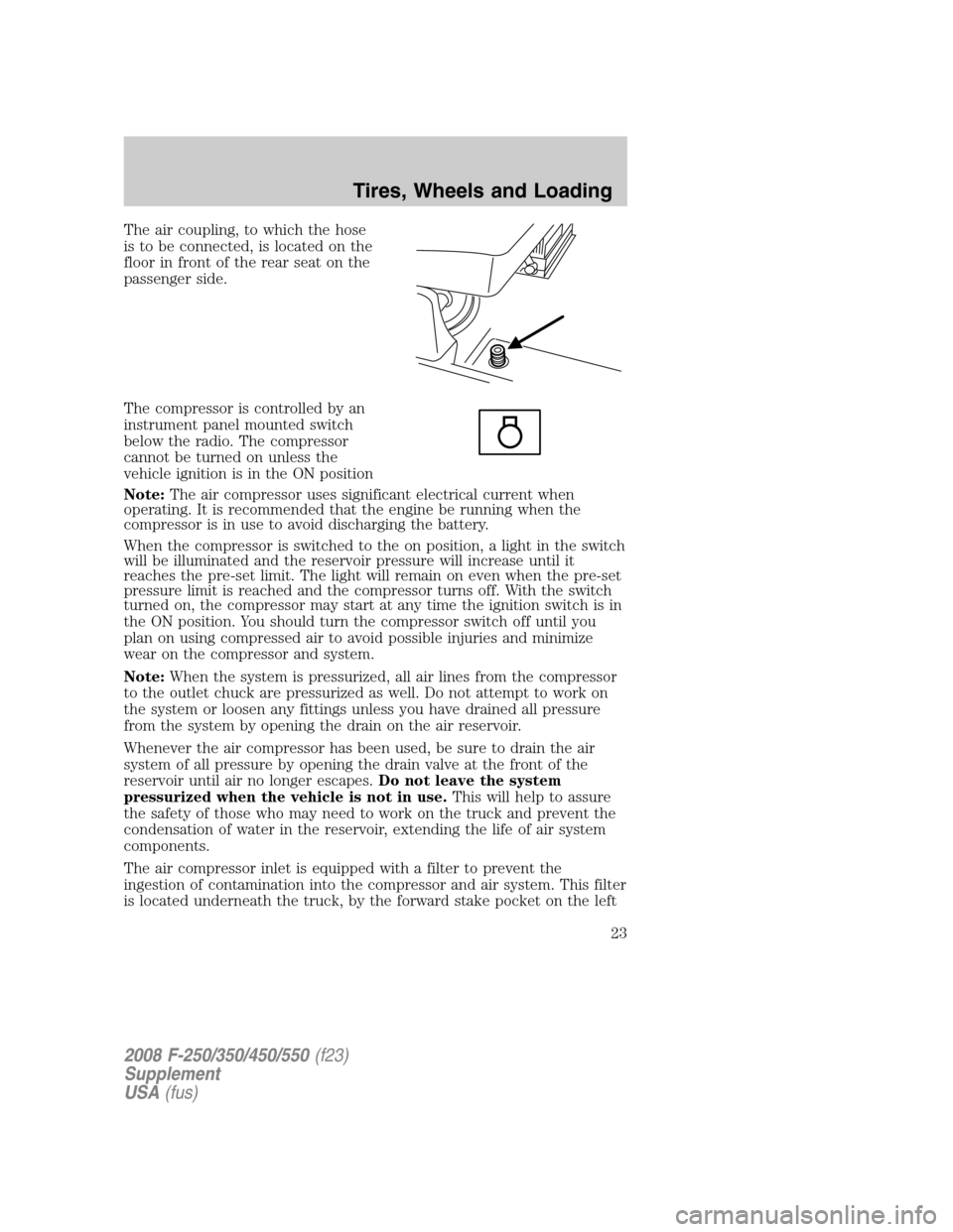
The air coupling, to which the hose
is to be connected, is located on the
floor in front of the rear seat on the
passenger side.
The compressor is controlled by an
instrument panel mounted switch
below the radio. The compressor
cannot be turned on unless the
vehicle ignition is in the ON position
Note:The air compressor uses significant electrical current when
operating. It is recommended that the engine be running when the
compressor is in use to avoid discharging the battery.
When the compressor is switched to the on position, a light in the switch
will be illuminated and the reservoir pressure will increase until it
reaches the pre-set limit. The light will remain on even when the pre-set
pressure limit is reached and the compressor turns off. With the switch
turned on, the compressor may start at any time the ignition switch is in
the ON position. You should turn the compressor switch off until you
plan on using compressed air to avoid possible injuries and minimize
wear on the compressor and system.
Note:When the system is pressurized, all air lines from the compressor
to the outlet chuck are pressurized as well. Do not attempt to work on
the system or loosen any fittings unless you have drained all pressure
from the system by opening the drain on the air reservoir.
Whenever the air compressor has been used, be sure to drain the air
system of all pressure by opening the drain valve at the front of the
reservoir until air no longer escapes.Do not leave the system
pressurized when the vehicle is not in use.This will help to assure
the safety of those who may need to work on the truck and prevent the
condensation of water in the reservoir, extending the life of air system
components.
The air compressor inlet is equipped with a filter to prevent the
ingestion of contamination into the compressor and air system. This filter
is located underneath the truck, by the forward stake pocket on the left
2008 F-250/350/450/550(f23)
Supplement
USA(fus)
Tires, Wheels and Loading
23
Page 24 of 25

side of the bed. If operating the air system in dusty areas, periodically
inspect this filter and replace it if found to be clogged or damaged, or if
the time needed to pressurize the system starts to become extended.
Using the air system to fill tires
To fill your tires, first be sure to stop the truck in a safe place. You
should be far enough off the road that passing traffic will not be a danger
to you. You should have an accurate tire pressure gauge to measure the
pressure in the tires and inflate them to the settings on the tire pressure
placard, which is usually inside the door on the truck.
Remove the air hose from under the clamp on the floor of the truck.
Attach the connector end of the hose to the coupling in the trim panel
behind the driver’s seat by using one hand to slide the coupling collar
toward the trim panel and the other to insert the fitting on the end of
the hose into the coupling. When the fitting is seated in the coupling,
slide the collar back to its original position.
Extend the hose to reach the tire needing air. Remove the cap from the
tire valve stem and attach the clamp-on air chuck by squeezing the
locking mechanism while placing the chuck over the valve stem. Release
the locking mechanism when the air chuck is seated on the stem. Air will
flow from the system to the tire until you remove the chuck. Be sure to
use your gauge to set the pressure according to the placard. When the
tire pressure is correct, disconnect the hose and re-stow it under the
clamp on the floor behind the passenger seat. Do not forget to re-install
the cap on the valve stem.
TIRE PRESSURE MONITORING SYSTEM (TPMS) (IF EQUIPPED)
If your vehicle is equipped with a Tire Pressure Monitoring System
(TPMS), refer to yourOwner’s Guidefor complete details on system
operation.
2008 F-250/350/450/550(f23)
Supplement
USA(fus)
Tires, Wheels and Loading
24
Page 25 of 25

CHANGING A FLAT TIRE
Refer to yourOwner’s Guidefor the tire changing procedure. Follow the
F-350 Dual Rear Wheel (DRW) jacking instructions.
FUSING
Note:Fuse 29 in the instrument panel box, located below and to the left
of the steering wheel, should be a 15A mini fuse. Always replace the fuse
you removed with a fuse with the same amperage rating.
2008 F-250/350/450/550(f23)
Supplement
USA(fus)
Roadside emergencies
25