service indicator FORD TAURUS 2015 6.G User Guide
[x] Cancel search | Manufacturer: FORD, Model Year: 2015, Model line: TAURUS, Model: FORD TAURUS 2015 6.GPages: 558, PDF Size: 4.42 MB
Page 198 of 558
PRINCIPLES OF OPERATION
The traction control system helps avoid drive wheel spin and loss of
traction.
If your vehicle begins to slide, the system applies the brakes to individual
wheels and, when needed, reduces engine power at the same time. If the
wheels spin when accelerating on slippery or loose surfaces, the system
reduces engine power in order to increase traction.
USING TRACTION CONTROL
Note:If your vehicle is equipped with MyKey®, it is possible to prevent
turning the traction control system off. See the MyKeychapter.
In certain situations (for example, stuck in snow or mud), turning the
traction control off may be beneficial as this allows the wheels to spin
with full engine power. Turn the traction control system off by pressing
the stability control button located in the access door under the climate
controls on Taurus SHO models, or through the information display on
other models.
System indicator lights and messages
WARNING: If a failure has been detected within the
AdvanceTrac® system, the stability control light will illuminate
steadily. Verify that the AdvanceTrac® system was not manually
disabled through using the information display control. If the stability
control light still illuminates steadily, have the system serviced by an
authorized dealer immediately. Operating your vehicle with
AdvanceTrac® disabled could lead to an increased risk of loss of
vehicle control, vehicle rollover, personal injury and death.
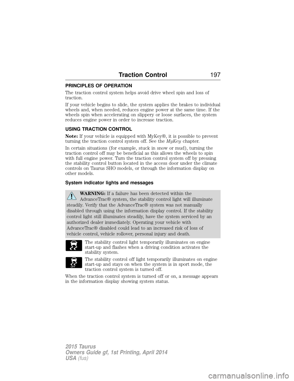
The stability control light temporarily illuminates on engine
start-up and flashes when a driving condition activates the
stability system.
The stability control off light temporarily illuminates on engine
start-up and stays on when the system is in sport mode, the
traction control system is turned off.
When the traction control system is turned off or on, a message appears
in the information display showing system status.
Traction Control 197
2015 Taurus
Owners Guide gf, 1st Printing, April 2014
USA(fus)
Page 291 of 558
Engine fluid temperature management (EcoBoost engine only)
WARNING:To reduce the risk of collision and injury, be
prepared that the vehicle speed may reduce and the vehicle may
not be able to accelerate with full power until the fluid temperatures
reduce.
Your vehicle has been designed to pull a trailer, but because of the added
load, the vehicle’s engine may temporarily reach higher temperatures
during severe operating conditions such as ascending a long or steep
grade while pulling a trailer in hot ambient temperatures.
At this time, you may notice your engine coolant temperature gauge
needle move toward the H (hot) and the POWER REDUCED TO LOWER
TEMP message may appear on the message center.
You may notice a reduction in the vehicle’s speed caused by reduced
engine power. Your vehicle has been designed to enter this mode if
certain high temperature/high load conditions take place in order to
manage the engine’s fluid temperatures. The amount of speed reduction
will depend on the vehicle loading, towing, grade, ambient temperature,
and other factors. If this occurs, there is no need to pull off the road.
The vehicle can continue to be driven while this message is active.
The air conditioning may also cycle on and off during severe operating
conditions to protect overheating of the engine. When the engine coolant
temperature decreases to a more normal operating temperature, the air
conditioning will turn on once again.
If you notice any of the following:
• the engine coolant temperature gauge moves fully into the red (hot)
area
• the coolant temperature warning light illuminates
• the service engine soon indicator illuminates
1. Pull off the road as soon as safely possible and place the vehicle in P
(Park).
2. Leave the engine running until the coolant temperature gauge needle
moves away from the H range. After several minutes, if this does not
happen, follow the remaining steps.
3. Turn the engine off and wait for it to cool before checking the coolant
level.
290 Maintenance
2015 Taurus
Owners Guide gf, 1st Printing, April 2014
USA(fus)
Page 292 of 558
WARNING:Never remove the coolant reservoir cap while the
engine is running or hot.
4. If the coolant level is normal, you may restart your engine and
continue on.
5. If the coolant is low, add coolant, restart the engine and take your
vehicle to an authorized dealer. See Adding engine coolantin this
chapter for more information.
Refer to fail-safe cooling for additional information.
What You Should Know About Fail-Safe Cooling
If the engine coolant supply is depleted, this feature allows the vehicle to
be driven temporarily before incremental component damage is incurred.
The fail-safe distance depends on ambient temperatures, vehicle load and
terrain.
How Fail-Safe Cooling Works
If the engine begins to overheat:
• The engine coolant temperature gauge will move to the red (hot)
area.
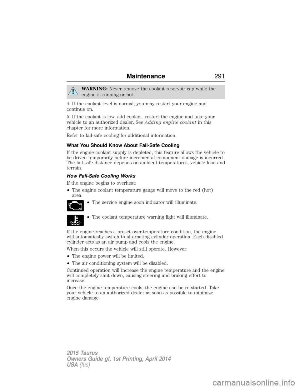
•The service engine soon indicator will illuminate.
• The coolant temperature warning light will illuminate.
If the engine reaches a preset over-temperature condition, the engine
will automatically switch to alternating cylinder operation. Each disabled
cylinder acts as an air pump and cools the engine.
When this occurs the vehicle will still operate. However:
• The engine power will be limited.
• The air conditioning system will be disabled.
Continued operation will increase the engine temperature and the engine
will completely shut down, causing steering and braking effort to
increase.
Once the engine temperature cools, the engine can be re-started. Take
your vehicle to an authorized dealer as soon as possible to minimize
engine damage.
Maintenance 291
2015 Taurus
Owners Guide gf, 1st Printing, April 2014
USA(fus)
Page 332 of 558
WARNING:To reduce the risk of serious injury, when mounting
replacement tires and wheels, you should not exceed the
maximum pressure indicated on the sidewall of the tire to set the beads
without additional precautions listed below. If the beads do not seat at
the maximum pressure indicated, re-lubricate and try again.
When inflating the tire for mounting pressures up to 20 psi (1.38 bar)
greater than the maximum pressure on the tire sidewall, the following
precautions must be taken to protect the person mounting the tire:
1. Make sure that you have the correct tire and wheel size.
2. Lubricate the tire bead and wheel bead seat area again.
3. Stand at a minimum of 12 feet (3.66 meters) away from the tire
wheel assembly.
4. Use both eye and ear protection.
For a mounting pressure more than 20 psi (1.38 bar) greater than the
maximum pressure, a Ford dealer or other tire service professional
should do the mounting.
Always inflate steel carcass tires with a remote air fill with the person
inflating standing at a minimum of 12 feet (3.66 meters) away from the
tire wheel assembly.
Your vehicle is equipped with tires designed to provide a safe ride and
handling capability.
Important: Remember to replace the wheel valve stems when the road
tires are replaced on your vehicle.
The two front tires or two rear tires should generally be replaced as a
pair.
The tire pressure sensors mounted in the wheels (originally installed on
your vehicle) are not designed to be used in aftermarket wheels.
The use of wheels or tires not recommended by Ford Motor Company
may affect the operation of your tire pressure monitoring system.
If the tire pressure monitoring system indicator is flashing, the system is
malfunctioning. Your replacement tire might be incompatible with your
tire pressure monitoring system, or some component of the system may
be damaged.
Wheels and Tires 331
2015 Taurus
Owners Guide gf, 1st Printing, April 2014
USA(fus)
Page 340 of 558
CHANGING A ROAD WHEEL
WARNING:The use of tire sealant may damage your tire pressure
monitoring system and should only be used in roadside emergencies.
If you must use a sealant, the Ford Tire Mobility Kit sealant should be
used. The tire pressure monitoring system sensor and valve stem on the
wheel must be replaced by an authorized dealer after use of the sealant.
WARNING: SeeTire Pressure Monitoring System in this
chapter for important information. If the tire pressure monitoring
sensor becomes damaged, it will no longer function.
Note: The tire pressure monitoring system indicator light will illuminate
when the spare tire is in use. To restore the full function of the
monitoring system, all road wheels equipped with tire pressure
monitoring sensors must be mounted on this vehicle.
If you get a flat tire while driving, do not apply the brake heavily.
Instead, gradually decrease your speed. Hold the steering wheel firmly
and slowly move to a safe place on the side of the road.
Have a flat serviced by an authorized dealer in order to prevent damage
to the system sensors. See Tire Pressure Monitoring System earlier in
this chapter. Replace the spare tire with a road tire as soon as possible.
During repairing or replacing of the flat tire, have the authorized dealer
inspect the tire pressure monitoring system sensor for damage.
Dissimilar Spare Tire and Wheel Assembly Information
WARNING: Failure to follow these guidelines could result in an
increased risk of loss of vehicle control, injury or death.
If you have a dissimilar spare tire and wheel assembly, then it is intended
for temporary use only. This means that if you need to use it, you should
replace it as soon as possible with a road tire and wheel assembly that is
the same size and type as the road tires and wheels that were originally
provided by Ford. If the dissimilar spare tire or wheel is damaged, it
should be replaced rather than repaired.
A dissimilar spare tire and wheel assembly is defined as a spare tire or
wheel that is different in brand, size or appearance from the road tires
and wheels and can be one of three types:
1. T-type mini-spare: This spare tire begins with the letter T for tire
size and may have Temporary Use Only molded in the sidewall.
Wheels and Tires 339
2015 Taurus
Owners Guide gf, 1st Printing, April 2014
USA(fus)
Page 553 of 558
Display settings .........................488
Driver alert ................................222
Driving under special
conditions ..................187, 190, 192sand .........................................191
snow and ice ...........................193
through water .................191, 255
Dual automatic temperature
control (DATC) .........131, 133, 135
E
Electronic message center .......110
Electronic stability control ......199
Emergencies, roadside jump-starting ..........................260
running out of fuel .................175
Emergency brake
(see Parking brake) ..................196
Emission control system ..........180
End user license agreement ....514
Engine ........................................356 cleaning ...................................311
coolant .....................................287
fail-safe cooling .......................291
idle speed control ...................298
lubrication specifications .......358
refill capacities ........................358
service points ..................283, 285
Engine block heater .................170
Engine oil checking and adding ..............286
dipstick ....................................286
filter, specifications ................363
refill capacities ........................358
specifications ..........................358
Event data recording ..................12
Exhaust fumes ..........................170 F
Fail safe cooling ........................291
Fleet MyKey programming ........64
Floor mats .................................256
Fluid capacities .........................358
Four-Wheel Drive vehicles
driving off road .......................189
Fuel cap ...........................................177
capacity ...................................358
choosing the right fuel ...173–174
filler funnel .............................175
filling your vehicle with fuel ..177
filter, specifications ........297, 363
fuel pump shut-off ..................259
octane rating ...................174, 356
quality ......................................173
running out of fuel .................175
safety information relating
to automotive fuels ................172
Fuel and distance computer ....114 outside temperature
indicator ..................................114
to empty indicator ..................114
trip distance ............................114
trip/reset button .....................114
Fuel - flex fuel vehicle
(FFV) .........................................174
Fuses ..........................................271
G
Garage door opener ..................156
Gas cap (see Fuel cap) ............177
Gauges ...............................103–104 odometer .................................114
trip odometer ..........................114
552 Index
2015 Taurus
Owners Guide gf, 1st Printing, April 2014
USA(fus)