FORD TRANSIT 2006 7.G Body And Equipment Mounting Section Manual
Manufacturer: FORD, Model Year: 2006, Model line: TRANSIT, Model: FORD TRANSIT 2006 7.GPages: 234, PDF Size: 33.19 MB
Page 21 of 234
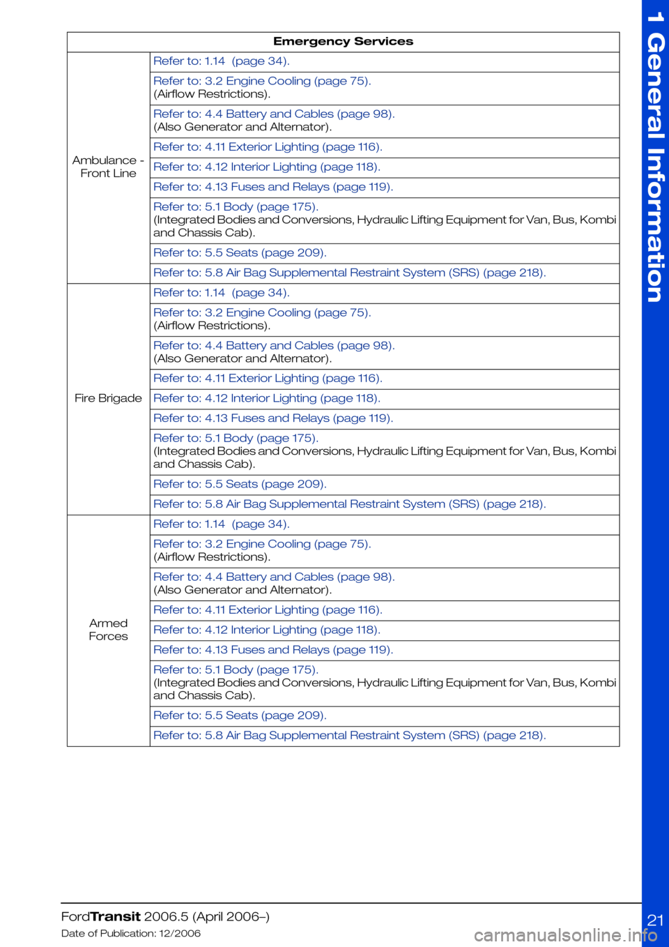
Emergency Services
Refer to: 1.14 (page 34).
Ambulance -
Front Line
Refer to: 3.2 Engine Cooling (page 75).
(Airflow Restrictions).
Refer to: 4.4 Battery and Cables (page 98).
(Also Generator and Alternator).
Refer to: 4.11 Exterior Lighting (page 116).
Refer to: 4.12 Interior Lighting (page 118).
Refer to: 4.13 Fuses and Relays (page 119).
Refer to: 5.1 Body (page 175).
(Integrated Bodies and Conversions, Hydraulic Lifting Equipment for Van, Bus, Kombi
and Chassis Cab).
Refer to: 5.5 Seats (page 209).
Refer to: 5.8 Air Bag Supplemental Restraint System (SRS) (page 218).
Refer to: 1.14 (page 34).
Fire Brigade
Refer to: 3.2 Engine Cooling (page 75).
(Airflow Restrictions).
Refer to: 4.4 Battery and Cables (page 98).
(Also Generator and Alternator).
Refer to: 4.11 Exterior Lighting (page 116).
Refer to: 4.12 Interior Lighting (page 118).
Refer to: 4.13 Fuses and Relays (page 119).
Refer to: 5.1 Body (page 175).
(Integrated Bodies and Conversions, Hydraulic Lifting Equipment for Van, Bus, Kombi
and Chassis Cab).
Refer to: 5.5 Seats (page 209).
Refer to: 5.8 Air Bag Supplemental Restraint System (SRS) (page 218).
Refer to: 1.14 (page 34).
Armed
Forces
Refer to: 3.2 Engine Cooling (page 75).
(Airflow Restrictions).
Refer to: 4.4 Battery and Cables (page 98).
(Also Generator and Alternator).
Refer to: 4.11 Exterior Lighting (page 116).
Refer to: 4.12 Interior Lighting (page 118).
Refer to: 4.13 Fuses and Relays (page 119).
Refer to: 5.1 Body (page 175).
(Integrated Bodies and Conversions, Hydraulic Lifting Equipment for Van, Bus, Kombi
and Chassis Cab).
Refer to: 5.5 Seats (page 209).
Refer to: 5.8 Air Bag Supplemental Restraint System (SRS) (page 218).
FordTransit 2006.5 (April 2006–)
Date of Publication: 12/2006
1 General Information
21
Page 22 of 234
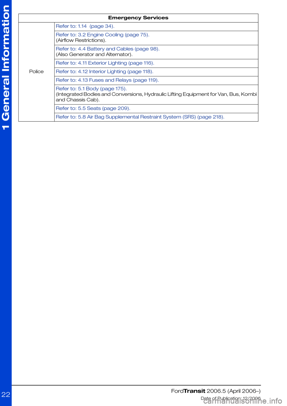
Emergency Services
Refer to: 1.14 (page 34).
Police
Refer to: 3.2 Engine Cooling (page 75).
(Airflow Restrictions).
Refer to: 4.4 Battery and Cables (page 98).
(Also Generator and Alternator).
Refer to: 4.11 Exterior Lighting (page 116).
Refer to: 4.12 Interior Lighting (page 118).
Refer to: 4.13 Fuses and Relays (page 119).
Refer to: 5.1 Body (page 175).
(Integrated Bodies and Conversions, Hydraulic Lifting Equipment for Van, Bus, Kombi
and Chassis Cab).
Refer to: 5.5 Seats (page 209).
Refer to: 5.8 Air Bag Supplemental Restraint System (SRS) (page 218).
FordTransit 2006.5 (April 2006–)
Date of Publication: 12/2006
1 General Information
22
Page 23 of 234
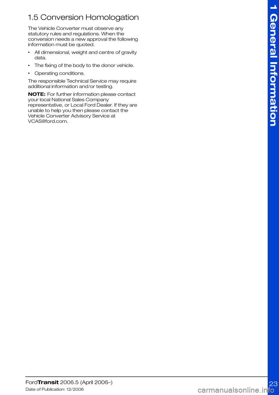
1.5 Conversion Homologation
The Vehicle Converter must observe any
statutory rules and regulations. When the
conversion needs a new approval the following
information must be quoted.
•All dimensional, weight and centre of gravity
data.
•The fixing of the body to the donor vehicle.
•Operating conditions.
The responsible Technical Service may require
additional information and/or testing.
NOTE: For further information please contact
your local National Sales Company
representative, or Local Ford Dealer. If they are
unable to help you then please contact the
Vehicle Converter Advisory Service at
[email protected].
FordTransit 2006.5 (April 2006–)
Date of Publication: 12/2006
1 General Information
23
Page 24 of 234
1.6 Electromagnetic Compatibility (EMC)
The base vehicle has been tested and certified
to all relevant legislation relating to
Electromagnetic Compatibility. All retrofitted
equipment must also comply with the relevant
legislation.
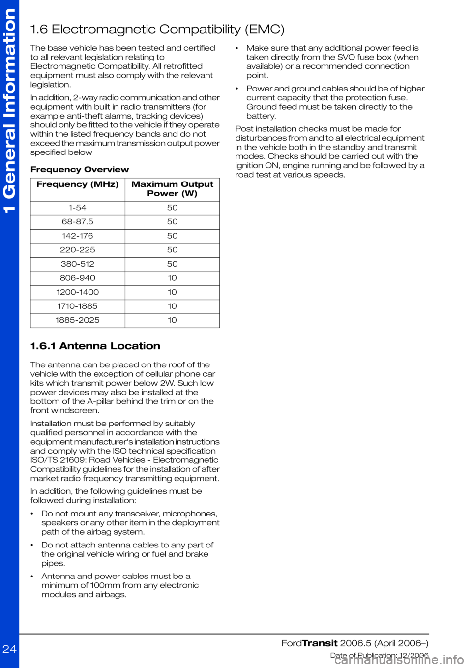
In addition, 2-way radio communication and other
equipment with built in radio transmitters (for
example anti-theft alarms, tracking devices)
should only be fitted to the vehicle if they operate
within the listed frequency bands and do not
exceed the maximum transmission output power
specified below
Frequency Overview
Maximum Output
Power (W)
Frequency (MHz)
501-54
5068-87.5
50142-176
50220-225
50380-512
10806-940
101200-1400
101710-1885
101885-2025
1.6.1 Antenna Location
The antenna can be placed on the roof of the
vehicle with the exception of cellular phone car
kits which transmit power below 2W. Such low
power devices may also be installed at the
bottom of the A-pillar behind the trim or on the
front windscreen.
Installation must be performed by suitably
qualified personnel in accordance with the
equipment manufacturer's installation instructions
and comply with the ISO technical specification
ISO/TS 21609: Road Vehicles - Electromagnetic
Compatibility guidelines for the installation of after
market radio frequency transmitting equipment.
In addition, the following guidelines must be
followed during installation:
•Do not mount any transceiver, microphones,
speakers or any other item in the deployment
path of the airbag system.
•Do not attach antenna cables to any part of
the original vehicle wiring or fuel and brake
pipes.
•Antenna and power cables must be a
minimum of 100mm from any electronic
modules and airbags.
•Make sure that any additional power feed is
taken directly from the SVO fuse box (when
available) or a recommended connection
point.
•Power and ground cables should be of higher
current capacity that the protection fuse.
Ground feed must be taken directly to the
battery.
Post installation checks must be made for
disturbances from and to all electrical equipment
in the vehicle both in the standby and transmit
modes. Checks should be carried out with the
ignition ON, engine running and be followed by a
road test at various speeds.
FordTransit 2006.5 (April 2006–)
Date of Publication: 12/2006
1 General Information
24
Page 25 of 234
1.7 Vehicle Duty Cycle Guidelines
It is necessary to take into account the customer
usage profile and the anticipated vehicle duty
cycles of the modified vehicle in order to choose
the appropriate specification of the base vehicle.
It is necessary to select the appropriate drive,
engine, gear ratio, gross vehicle mass, gross train
mass, axle plates and payloads of the base
vehicle to match the customer requirements.
Where possible make sure that the base vehicle
is ordered with any necessary plant fit options.
NOTE: For further information please contact
your local National Sales Company
representative, or Local Ford Dealer. If they are
unable to help you then please contact the
Vehicle Converter Advisory Service at
[email protected].
A high numeric gear ratio is recommended for
vehicles with customer requirements for:
•high payload
•trailer tow
•frequent stop-and-go cycles
•high altitude and gradients
•terrain conditions such as found on building
and construction sites
Rear wheel drive is recommended for high
traction in combination with a high trailer weight
Front wheel drive is recommended for low
conversion weight
1.7.1 Conversion Affect on Fuel
Economy and Performance
Any conversion may effect the fuel consumption
and performance depending on the
aerodynamics and the weight added by the
conversion. The published information for fuel
consumption and performance of the base
vehicle therefore may not be valid. It is advisable
to control the weight, but without deteriorating
other vehicle attributes and functions (especially
those related to safety and durability).
1.7.2 Vehicle Ride and Handling
Attributes
CAUTION: Do not exceed the axle
plate, gross vehicle mass, trailer
plate and gross trailer mass limits.
Due to the displacement of the center of gravity
occurred by the conversion the ride and handling
attributes may be different to the base vehicle.
NOTE: This vehicle should be evaluated for safe
operation prior to sale
FordTransit 2006.5 (April 2006–)
Date of Publication: 12/2006
1 General Information
25
Page 26 of 234
1.8 End of Life Vehicle (ELV) Directive
The EU End-of-Life Vehicle (ELV) directive
requires that environmental and recycling aspects
are integrated in the development process of
new components and vehicles. This includes
requirements with aspect to:
•The overall recyclability (85%) / recoverability
(95%) of vehicles.
•Limited use of hazardous substances including
the elimination of prohibited substances such
as lead, hexavalent chromium cadmium and
mercury).
•Publication of dismantling information.
•Parts Marking according to the corresponding
ISO Standards: ISO 1043-1, 1043-2 and 11469
for plastics and ISO 1629 for rubber materials.
•Increasing use of recycled materials.
•Producers meet all, or a significant part of, the
costs to take back End-of-Life Vehicles
In addition to the requirements resulting from the
End-of-Life directive other environmental targets
should be taken into consideration such as:
•minimizing costs and environmental burden
along the product life-cycle.
•Maximizing use of renewable materials e.g.
natural fibres.
•minimizing the presence of substances
impacting vehicle interior air quality / clean
compartment or allergenic reactions (please
refer to 'Technischer Überwachungsverein
TÜV TOXPROOF). This refers to aspects like
smell, fogging, toxicity and allergy coming from
material in the interior.
•eliminate use of prohibited substances which
are listed in the Global Automotive Declarable
Substance List (GADSL) at
http://www.gadsl.org.
For continued legal compliance and
environmental performance of all Ford products
it is essential that any conversion of the vehicles
is in compliance with the requirements listed
above.
This is not a complete list of all legal requirements
to be met by every converted vehicle.
NOTE: For further information please contact
your local National Sales Company representative,
or Local Ford Dealer. If they are unable to help
you then please contact the Vehicle Converter
Advisory Service at [email protected].
FordTransit 2006.5 (April 2006–)
Date of Publication: 12/2006
1 General Information
26
Page 27 of 234
1.9 Jacking
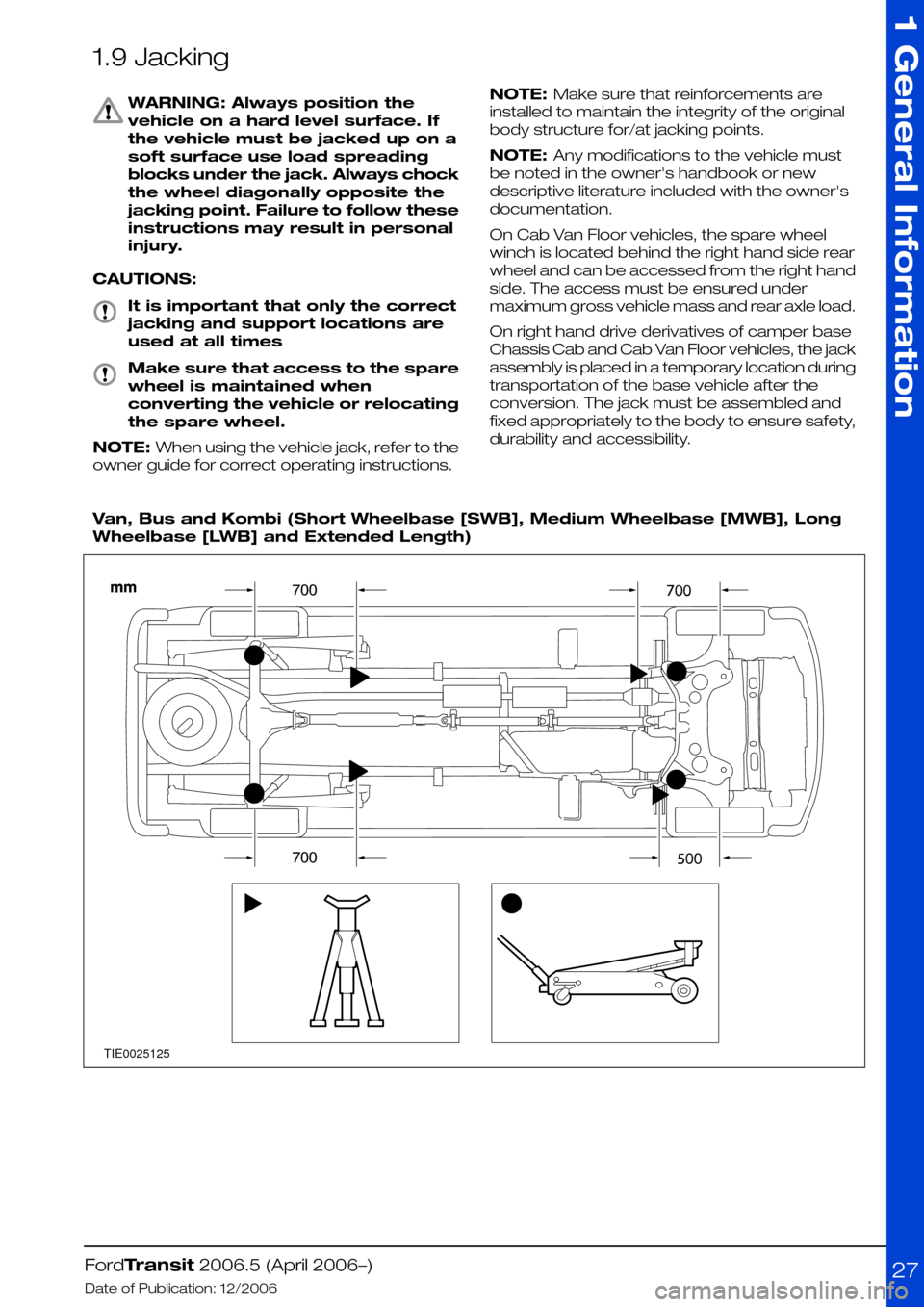
WARNING: Always position the
vehicle on a hard level surface. If
the vehicle must be jacked up on a
soft surface use load spreading
blocks under the jack. Always chock
the wheel diagonally opposite the
jacking point. Failure to follow these
instructions may result in personal
injury.
CAUTIONS:
It is important that only the correct
jacking and support locations are
used at all times
Make sure that access to the spare
wheel is maintained when
converting the vehicle or relocating
the spare wheel.
NOTE: When using the vehicle jack, refer to the
owner guide for correct operating instructions.
NOTE: Make sure that reinforcements are
installed to maintain the integrity of the original
body structure for/at jacking points.
NOTE: Any modifications to the vehicle must
be noted in the owner's handbook or new
descriptive literature included with the owner's
documentation.
On Cab Van Floor vehicles, the spare wheel
winch is located behind the right hand side rear
wheel and can be accessed from the right hand
side. The access must be ensured under
maximum gross vehicle mass and rear axle load.
On right hand drive derivatives of camper base
Chassis Cab and Cab Van Floor vehicles, the jack
assembly is placed in a temporary location during
transportation of the base vehicle after the
conversion. The jack must be assembled and
fixed appropriately to the body to ensure safety,
durability and accessibility.
Van, Bus and Kombi (Short Wheelbase [SWB], Medium Wheelbase [MWB], Long
Wheelbase [LWB] and Extended Length)
FordTransit 2006.5 (April 2006–)
Date of Publication: 12/2006
1 General Information
27TIE0025125
Page 28 of 234
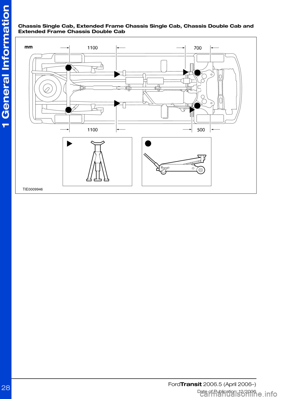
Chassis Single Cab, Extended Frame Chassis Single Cab, Chassis Double Cab and
Extended Frame Chassis Double Cab
FordTransit 2006.5 (April 2006–)
Date of Publication: 12/2006
1 General Information
28TIE0009946
Page 29 of 234
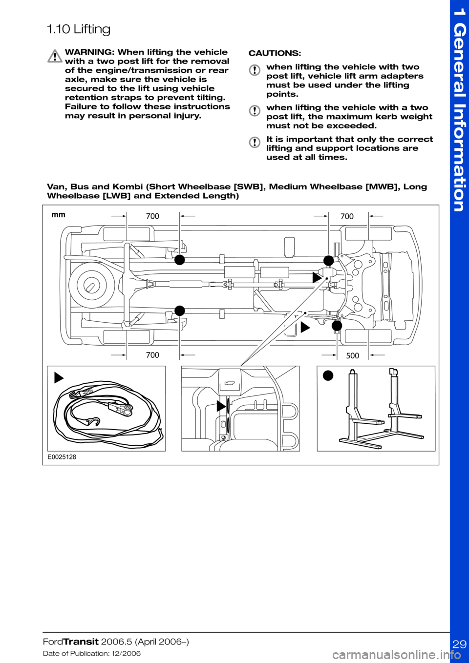
1.10 Lifting
WARNING: When lifting the vehicle
with a two post lift for the removal
of the engine/transmission or rear
axle, make sure the vehicle is
secured to the lift using vehicle
retention straps to prevent tilting.
Failure to follow these instructions
may result in personal injury.
CAUTIONS:
when lifting the vehicle with two
post lift, vehicle lift arm adapters
must be used under the lifting
points.
when lifting the vehicle with a two
post lift, the maximum kerb weight
must not be exceeded.
It is important that only the correct
lifting and support locations are
used at all times.
Van, Bus and Kombi (Short Wheelbase [SWB], Medium Wheelbase [MWB], Long
Wheelbase [LWB] and Extended Length)
FordTransit 2006.5 (April 2006–)
Date of Publication: 12/2006
1 General Information
29E0025128
Page 30 of 234
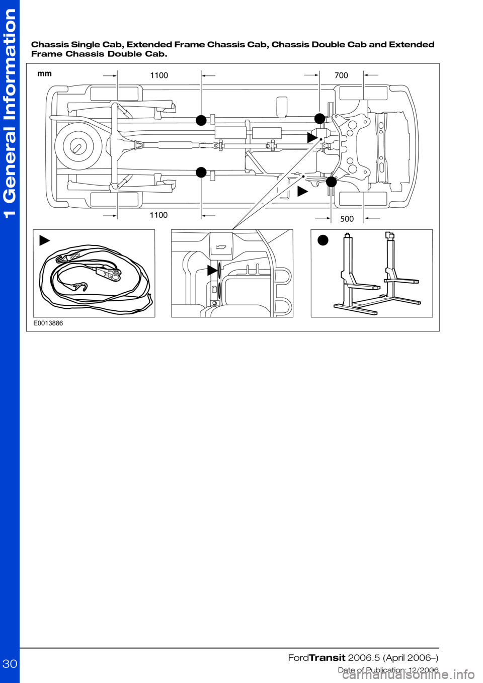
Chassis Single Cab, Extended Frame Chassis Cab, Chassis Double Cab and Extended
Frame Chassis Double Cab.
FordTransit 2006.5 (April 2006–)
Date of Publication: 12/2006
1 General Information
30E0013886