relay FORD TRANSIT 2006 7.G Body And Equipment Mounting Section Manual
[x] Cancel search | Manufacturer: FORD, Model Year: 2006, Model line: TRANSIT, Model: FORD TRANSIT 2006 7.GPages: 234, PDF Size: 33.19 MB
Page 128 of 234
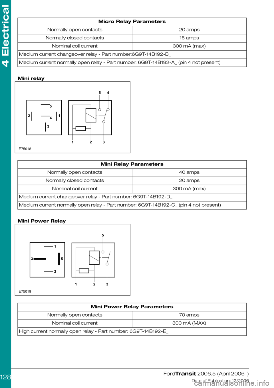
Micro Relay Parameters
20 ampsNormally open contacts
16 ampsNormally closed contacts
300 mA (max)Nominal coil current
Medium current changeover relay - Part number:6G9T-14B192-B_
Medium current normally open relay - Part number: 6G9T-14B192-A_ (pin 4 not present)
Mini relay
Mini Relay Parameters
40 ampsNormally open contacts
20 ampsNormally closed contacts
300 mA (max)Nominal coil current
Medium current changeover relay - Part number: 6G9T-14B192-D_
Medium current normally open relay - Part number: 6G9T-14B192-C_ (pin 4 not present)
Mini Power Relay
Mini Power Relay Parameters
70 ampsNormally open contacts
300 mA (MAX)Nominal coil current
High current normally open relay - Part number: 6G9T-14B192-E_
FordTransit 2006.5 (April 2006–)
Date of Publication: 12/2006
4 Electrical
128E750181234512354 E7501912351235
Page 129 of 234
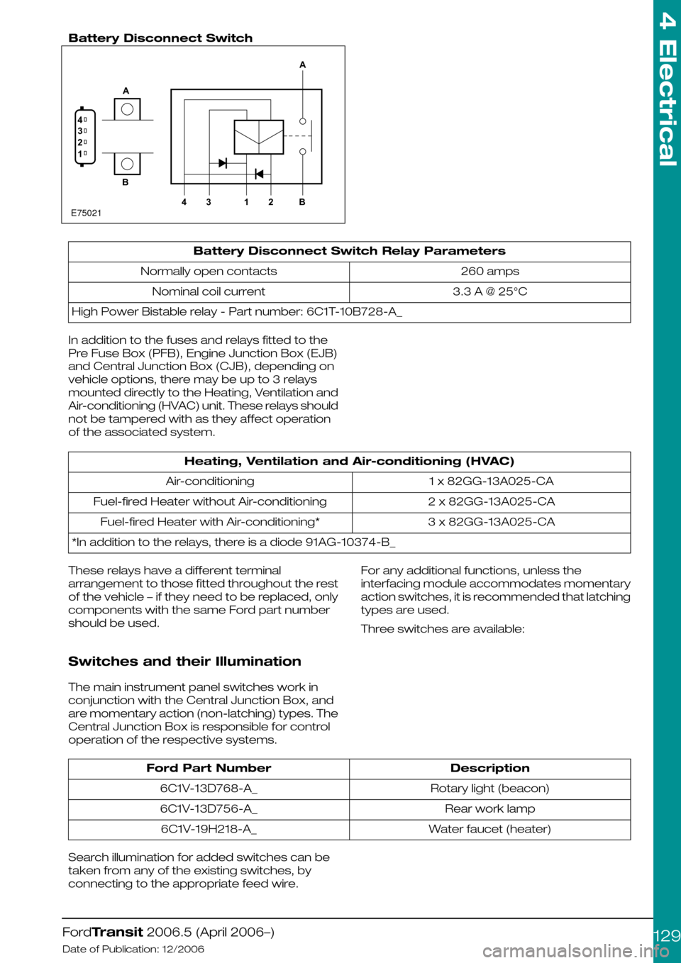
Battery Disconnect Switch
Battery Disconnect Switch Relay Parameters
260 ampsNormally open contacts
3.3 A @ 25°CNominal coil current
High Power Bistable relay - Part number: 6C1T-10B728-A_
In addition to the fuses and relays fitted to the
Pre Fuse Box (PFB), Engine Junction Box (EJB)
and Central Junction Box (CJB), depending on
vehicle options, there may be up to 3 relays
mounted directly to the Heating, Ventilation and
Air-conditioning (HVAC) unit. These relays should
not be tampered with as they affect operation
of the associated system.
Heating, Ventilation and Air-conditioning (HVAC)
1 x 82GG-13A025-CAAir-conditioning
2 x 82GG-13A025-CAFuel-fired Heater without Air-conditioning
3 x 82GG-13A025-CAFuel-fired Heater with Air-conditioning*
*In addition to the relays, there is a diode 91AG-10374-B_
These relays have a different terminal
arrangement to those fitted throughout the rest
of the vehicle – if they need to be replaced, only
components with the same Ford part number
should be used.
Switches and their Illumination
The main instrument panel switches work in
conjunction with the Central Junction Box, and
are momentary action (non-latching) types. The
Central Junction Box is responsible for control
operation of the respective systems.
For any additional functions, unless the
interfacing module accommodates momentary
action switches, it is recommended that latching
types are used.
Three switches are available:
DescriptionFord Part Number
Rotary light (beacon)6C1V-13D768-A_
Rear work lamp6C1V-13D756-A_
Water faucet (heater)6C1V-19H218-A_
Search illumination for added switches can be
taken from any of the existing switches, by
connecting to the appropriate feed wire.
FordTransit 2006.5 (April 2006–)
Date of Publication: 12/2006
4 Electrical
129E750211234AB4312BA
Page 130 of 234
4.13.7 Windscreen wipers
NOTE: Power to wiper motors is limited by the
size of the wiring and associated relays. If any
alternative wiper installation is made, it must have
a specification equivalent to Ford components.
Refer to: 5.6 Glass, Frames and Mechanisms
(page 211).
The base wiper system should not be tampered
with (controlled by Central Junction Box and
multiplex architecture).
Headlamp wash – such installations would need
to be controlled via an external timer relay. The
Special Vehicle Option Auxiliary Fuse Box should
be utilized.
Heated washer jets – aftermarket systems should
be fitted via an ignition feed, via an additional relay.
The Special Vehicle Option Auxiliary Fuse Box
should be utilized.
FordTransit 2006.5 (April 2006–)
Date of Publication: 12/2006
4 Electrical
130
Page 132 of 234
4.14.2 Engine Run Signal (D+ Alternative)
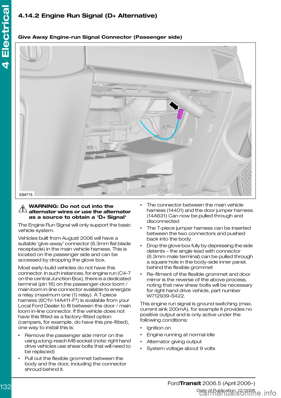
Give Away Engine-run Signal Connector (Passenger side)
WARNING: Do not cut into the
alternator wires or use the alternator
as a source to obtain a 'D+ Signal'
The Engine Run Signal will only support the basic
vehicle system.
Vehicles built from August 2006 will have a
suitable ‘give-away’ connector (6.3mm flat blade
receptacle) in the main vehicle harness. This is
located on the passenger side and can be
accessed by dropping the glove box.
Most early-build vehicles do not have this
connector. In such instances, for engine run (C4-7
on the central Junction Box), there is a dedicated
terminal (pin 16) on the passenger-door loom /
main loom in-line connector available to energize
a relay (maximum one (1) relay). A T-piece
harness (6C1V-14A411-F*) is available from your
Local Ford Dealer to fit between the door / main
loom in-line connector. If the vehicle does not
have this fitted as a factory-fitted option
(campers, for example, do have this pre-fitted),
one way to install this is:
•Remove the passenger side mirror on the
using a long-reach M8 socket (note: right hand
drive vehicles use shear bolts that will need to
be replaced)
•Pull out the flexible grommet between the
body and the door, including the connector
shroud behind it.
•The connector between the main vehicle
harness (14401) and the door jumper harness
(14A631) Can now be pulled through and
disconnected
•The T-piece jumper harness can be inserted
between the two connectors and pushed
back into the body.
•Drop the glove box fully by depressing the side
detents – the single lead with connector
(6.3mm male terminal) can be pulled through
a square hole in the body-side inner panel,
behind the flexible grommet
•Re-fitment of the flexible grommet and door
mirror is the reverse of the above process,
noting that new shear bolts will be necessary
for right hand drive vehicle, part number
W712939-S422.
This engine run signal is ground switching (max.
current sink 200mA), for example it provides no
positive output and is only active under the
following conditions:
•Ignition on
•Engine running at normal idle
•Alternator giving output
•System voltage about 9 volts
FordTransit 2006.5 (April 2006–)
Date of Publication: 12/2006
4 Electrical
132E84715
Page 133 of 234
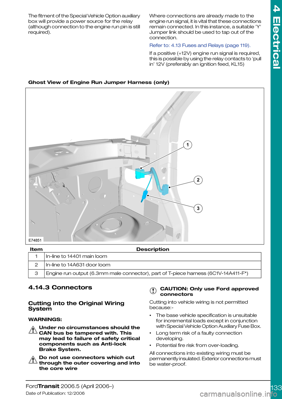
The fitment of the Special Vehicle Option auxiliary
box will provide a power source for the relay
(although connection to the engine run pin is still
required).
Where connections are already made to the
engine run signal, it is vital that these connections
remain connected. In this instance, a suitable 'Y'
Jumper link should be used to tap out of the
connection.
Refer to: 4.13 Fuses and Relays (page 119).
If a positive (+12V) engine run signal is required,
this is possible by using the relay contacts to ‘pull
in’ 12V (preferably an ignition feed, KL15)
Ghost View of Engine Run Jumper Harness (only)
DescriptionItem
In-line to 14401 main loom1
In-line to 14A631 door loom2
Engine run output (6.3mm male connector), part of T-piece harness (6C1V-14A411-F*)3
4.14.3 Connectors
Cutting into the Original Wiring
System
WARNINGS:
Under no circumstances should the
CAN bus be tampered with. This
may lead to failure of safety critical
components such as Anti-lock
Brake System.
Do not use connectors which cut
through the outer covering and into
the core wire
CAUTION: Only use Ford approved
connectors
Cutting into vehicle wiring is not permitted
because:-
•The base vehicle specification is unsuitable
for incremental loads except in conjunction
with Special Vehicle Option Auxiliary Fuse Box.
•Long term risk of a faulty connection
developing.
•Potential fire risk from over-loading.
All connections into existing wiring must be
permanently insulated. Exterior connections must
be water-proof.
FordTransit 2006.5 (April 2006–)
Date of Publication: 12/2006
4 Electrical
133132E74851
Page 137 of 234
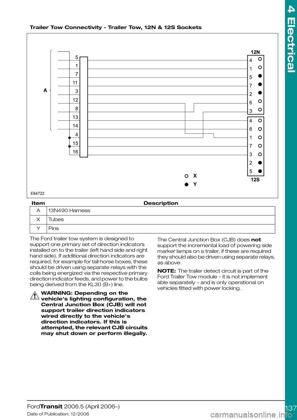
Trailer Tow Connectivity - Trailer Tow, 12N & 12S Sockets
DescriptionItem
13N490 HarnessA
TubesX
PinsY
The Ford trailer tow system is designed to
support one primary set of direction indicators
installed on to the trailer (left hand side and right
hand side). If additional direction indicators are
required, for example for tall horse boxes, these
should be driven using separate relays with the
coils being energized via the respective primary
direction indicator feeds, and power to the bulbs
being derived from the KL30 (B+) line.
WARNING: Depending on the
vehicle's lighting configuration, the
Central Junction Box (CJB) will not
support trailer direction indicators
wired directly to the vehicle's
direction indicators. If this is
attempted, the relevant CJB circuits
may shut down or perform illegally.
The Central Junction Box (CJB) does not
support the incremental load of powering side
marker lamps on a trailer, if these are required
they should also be driven using separate relays,
as above.
NOTE: The trailer detect circuit is part of the
Ford Trailer Tow module – it is not implement
able separately – and is only operational on
vehicles fitted with power locking.
FordTransit 2006.5 (April 2006–)
Date of Publication: 12/2006
4 Electrical
137E8472241572634617325517113128131441516
Page 147 of 234
4.14.8 Additional Vehicle Signals
/ Features
Reverse Signal
A reverse signal is available on the tail light
connector. In order to avoid electrical issues due
to leakage, and to ensure connector
compatibility, a mating connector with
seals/plugs and pre-crimped wire & terminal
should be used. For Additional information refer
to Adding Connectors, Terminals and Wiring in
this manual.
NOTE: It is not recommended that signal is used
to drive auxiliary equipment directly – a relay (max
300mA) should be used. The existing reverse
light load is close to the threshold and is
hard-wired through the Central Junction Box for
current sensing to generate the appropriate CAN
message.
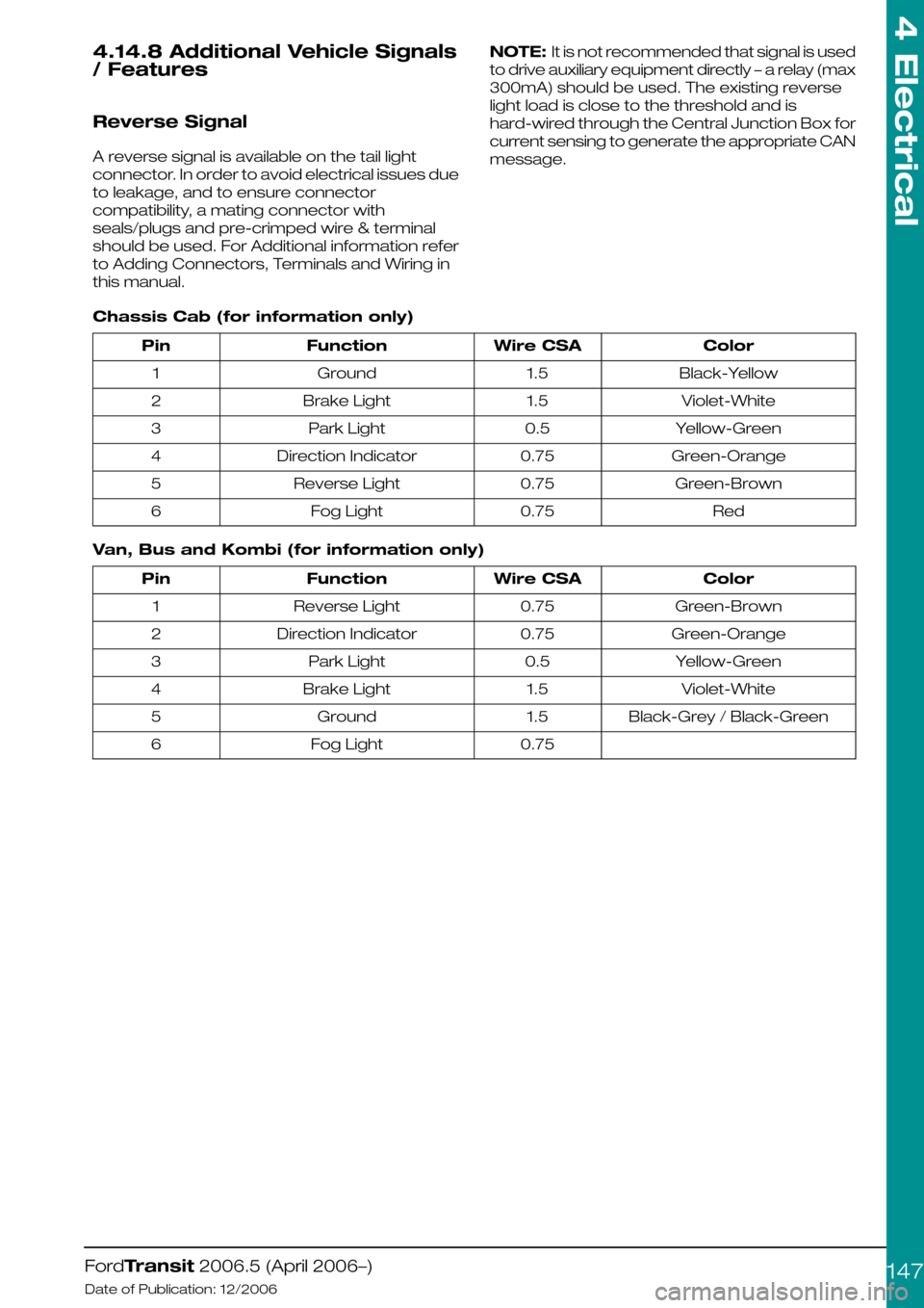
Chassis Cab (for information only)
ColorWire CSAFunctionPin
Black-Yellow1.5Ground1
Violet-White1.5Brake Light2
Yellow-Green0.5Park Light3
Green-Orange0.75Direction Indicator4
Green-Brown0.75Reverse Light5
Red0.75Fog Light6
Van, Bus and Kombi (for information only)
ColorWire CSAFunctionPin
Green-Brown0.75Reverse Light1
Green-Orange0.75Direction Indicator2
Yellow-Green0.5Park Light3
Violet-White1.5Brake Light4
Black-Grey / Black-Green1.5Ground5
0.75Fog Light6
FordTransit 2006.5 (April 2006–)
Date of Publication: 12/2006
4 Electrical
147
Page 150 of 234
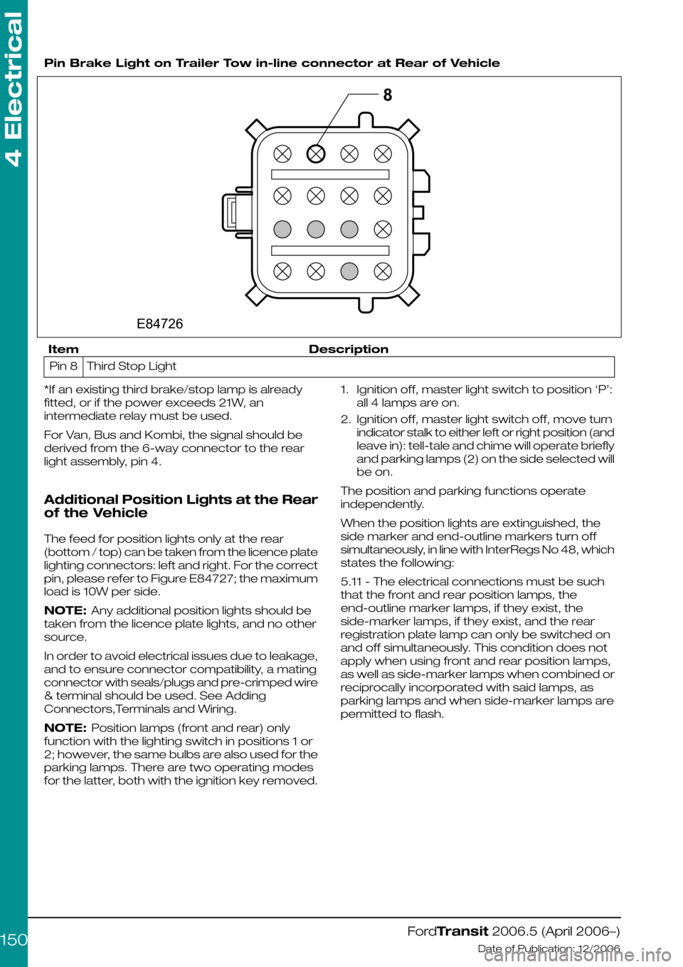
Pin Brake Light on Trailer Tow in-line connector at Rear of Vehicle
DescriptionItem
Third Stop LightPin 8
*If an existing third brake/stop lamp is already
fitted, or if the power exceeds 21W, an
intermediate relay must be used.
For Van, Bus and Kombi, the signal should be
derived from the 6-way connector to the rear
light assembly, pin 4.
Additional Position Lights at the Rear
of the Vehicle
The feed for position lights only at the rear
(bottom / top) can be taken from the licence plate
lighting connectors: left and right. For the correct
pin, please refer to Figure E84727; the maximum
load is 10W per side.
NOTE: Any additional position lights should be
taken from the licence plate lights, and no other
source.
In order to avoid electrical issues due to leakage,
and to ensure connector compatibility, a mating
connector with seals/plugs and pre-crimped wire
& terminal should be used. See Adding
Connectors,Terminals and Wiring.
NOTE: Position lamps (front and rear) only
function with the lighting switch in positions 1 or
2; however, the same bulbs are also used for the
parking lamps. There are two operating modes
for the latter, both with the ignition key removed.
1.Ignition off, master light switch to position ‘P’:
all 4 lamps are on.
2.Ignition off, master light switch off, move turn
indicator stalk to either left or right position (and
leave in): tell-tale and chime will operate briefly
and parking lamps (2) on the side selected will
be on.
The position and parking functions operate
independently.
When the position lights are extinguished, the
side marker and end-outline markers turn off
simultaneously, in line with InterRegs No 48, which
states the following:
5.11 - The electrical connections must be such
that the front and rear position lamps, the
end-outline marker lamps, if they exist, the
side-marker lamps, if they exist, and the rear
registration plate lamp can only be switched on
and off simultaneously. This condition does not
apply when using front and rear position lamps,
as well as side-marker lamps when combined or
reciprocally incorporated with said lamps, as
parking lamps and when side-marker lamps are
permitted to flash.
FordTransit 2006.5 (April 2006–)
Date of Publication: 12/2006
4 Electrical
1508E84726
Page 151 of 234
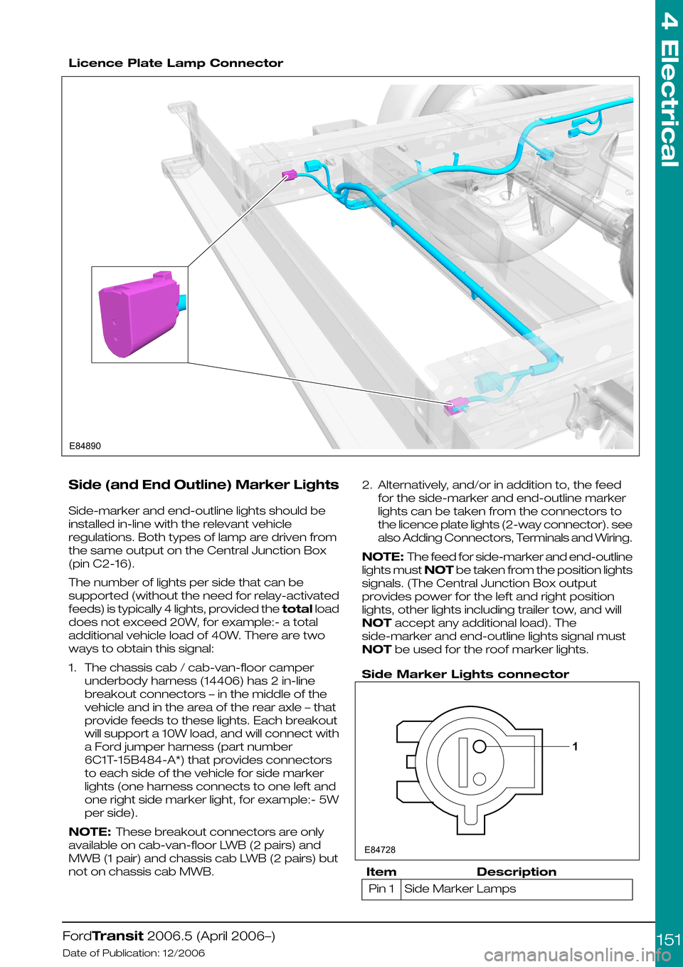
Licence Plate Lamp Connector
Side (and End Outline) Marker Lights
Side-marker and end-outline lights should be
installed in-line with the relevant vehicle
regulations. Both types of lamp are driven from
the same output on the Central Junction Box
(pin C2-16).
The number of lights per side that can be
supported (without the need for relay-activated
feeds) is typically 4 lights, provided the total load
does not exceed 20W, for example:- a total
additional vehicle load of 40W. There are two
ways to obtain this signal:
1.The chassis cab / cab-van-floor camper
underbody harness (14406) has 2 in-line
breakout connectors – in the middle of the
vehicle and in the area of the rear axle – that
provide feeds to these lights. Each breakout
will support a 10W load, and will connect with
a Ford jumper harness (part number
6C1T-15B484-A*) that provides connectors
to each side of the vehicle for side marker
lights (one harness connects to one left and
one right side marker light, for example:- 5W
per side).
NOTE: These breakout connectors are only
available on cab-van-floor LWB (2 pairs) and
MWB (1 pair) and chassis cab LWB (2 pairs) but
not on chassis cab MWB.
2.Alternatively, and/or in addition to, the feed
for the side-marker and end-outline marker
lights can be taken from the connectors to
the licence plate lights (2-way connector). see
also Adding Connectors, Terminals and Wiring.
NOTE: The feed for side-marker and end-outline
lights must NOT be taken from the position lights
signals. (The Central Junction Box output
provides power for the left and right position
lights, other lights including trailer tow, and will
NOT accept any additional load). The
side-marker and end-outline lights signal must
NOT be used for the roof marker lights.
Side Marker Lights connector
DescriptionItem
Side Marker LampsPin 1
FordTransit 2006.5 (April 2006–)
Date of Publication: 12/2006
4 Electrical
151E84890 1E84728
Page 154 of 234
harness that provides roof-mounted rear turn
indicators, powered via relays. This should be
used in conjunction with SVO fusebox.
3.Chassis cab LED rear lamp cluster
replacement recommendations, especially
turn indicator relay implications – see lighting
load table. Generally the use of LED equivalent
lighting systems reduces the electrical load on
the vehicle; however, special care needs to
be taken with respect to any change to or
addition of turn indicator lights. Depending on
the current requirements of the LED(s)
compared to the bulb it is replacing, a ballast
resistor may be required, if not already
integrated into the LED lamp assembly.
Without this, bulb outage detection for turn
indicators will be affected, which is a legal
requirement.
Additional turn indicators must be powered
through relays (max 300mA), driven by existing
turn lights. The maximum load that the Central
Junction Box can drive is 3 x 21W per side (front,
rear and CAT 6 turn indicators); but even if the
vehicle is not fitted with the CAT 6 lights, the feeds
for these should not be used as the Central
Junction Box would need reconfiguring, which
could have safety as well as functional
implications.
4.Special Vehicle Option beacon switch: wiring
locations, circuit diagrams and max amperage
– see Special Vehicle Option fuse box
schematic (max current is 15A); there is
provision for the Special Vehicle Option beacon
switch in an empty switch location on the
instrument panel.
5.Rear loom connector detail location and supply
details for retro-fit loom extension for
example:- when extending a medium wheel
base, long wheel base or extended frame
overhang, what connectors do they use to
make a plug and play loom extension? – for
chassis cab vehicles, there is an Special
Vehicle Option extension loom for rear lamps
(part number 6C1V-14408-A*). There is not, at
present, a similar loom for Van, Bus and
Kombi's, although the appropriate mating
connector is now tooled, so this would be
possible.
Miscellaneous Systems
Handbrake on - Cluster Warning Light -
Unless the vehicle is specified with options that
drive the handbrake warning light (for example
ESP, Australia market), the components making
up this system are not fitted. We do not
recommend installation of this feature as an
aftermarket addition. There are several reasons
for this:
1.Not all circuits carry the requisite wire as a give
away:
•The wires might be part of the main vehicle
harness (14401) even if not used – for example
camper vehicles are normally ordered with
power mirrors, and the wires will be present
as a give-away.
•The seat pedestal harness (14K076), however,
is vehicle specific – if the handbrake is not part
of the specification, it will not be present or
give-away. This harness would need to be
changed to the compatible part that also
includes the handbrake warning light circuit.
2.The handbrake switch (part number
2F2T-15852-A*) together with its short jumper
harness (6C1T-15K857-A*) would need to be
obtained and fitted.
3.The handbrake warning light is in all clusters,
but unless the vehicle config. parameter
“parking brake switch” is set, the Central
Junction Box will not read this input, and hence
NO CAN message sent to the cluster.
Reconfiguration can only be done at a Ford
Dealer.
NOTE: If a vehicle already has a handbrake
warning light in the cluster, or one is installed as
per the Ford design, it is not possible to utilize the
wire from the handbrake switch as part of an
interlock circuit (this is a pull up resistor input that
provides a wetting current of 20mA – anything in
excess of this, for example through additional
circuitry, will almost certainly damage the Central
Junction Box). If there is no handbrake switch
installed, it would be possible to add one and
utilize this as part of a separate circuit, up to a
maximum current of 500mA through the switch.
Reverse Sensors (Rear Park Aid
Module)- The factory-fit option is a CAN-based
system, but for Van, Bus, and Kombi vehicles
only. Stand-alone systems can be installed (for
example for chassis cab conversions), but would
need to utilize the PTA line of the radio if muting
is required.
Fuel Fired Heater (FFH)- Add FFH: wiring is
only present (give-away) in certain harnesses.
There was an aftermarket kit available for this
system on current Transit, which could probably
be “updated” to suit V347/8.
Fuel Fired Heater (FFH) - Programmable
FFH: this utilizes a timer/control module mounted
to the Instrument Panel, which necessitates
having the correct Instrument Panel harness
fitted. Retrofit of this would be a difficult.
For both systems, the appropriate 6C1T-14K132
harness would be required (suffix -A* for
Programmable FFH, and suffix –B* for Add FFH).
Central Locking
Locking is controlled by the Central Junction Box
module. There is current sensing on certain
locking circuit pins as part of the security system
– if these are tampered with, locking cannot be
guaranteed.
FordTransit 2006.5 (April 2006–)
Date of Publication: 12/2006
4 Electrical
154