relay FORD TRANSIT 2006 7.G Body And Equipment Mounting Section Manual
[x] Cancel search | Manufacturer: FORD, Model Year: 2006, Model line: TRANSIT, Model: FORD TRANSIT 2006 7.GPages: 234, PDF Size: 33.19 MB
Page 155 of 234

However, it is possible to add an additional lock(s)
– see also the section covering the ‘third button
on key fob’ – but only by utilizing relays (the
electric locks are operated by surface mounted
relays in the Central Junction Box – these are
only capable of powering one lock each, in
addition to which the output of these devices is
current-sensed to check it is within minimum and
maximum limits: I) to verify operation, and ii) as
part of the security system). For camper vehicles,
the Central Junction Box is configured for a
chassis cab vehicle.
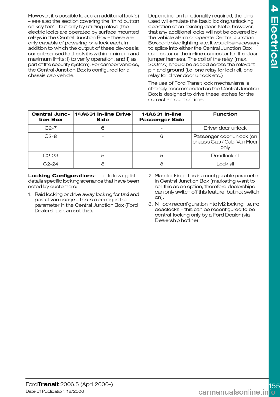
Depending on functionality required, the pins
used will emulate the basic locking/unlocking
operation of an existing door. Note, however,
that any additional locks will not be covered by
the vehicle alarm or operate Central Junction
Box controlled lighting, etc. It would be necessary
to splice into either the Central Junction Box
connector or the in-line connector for the door
jumper harness. The coil of the relay (max.
300mA) should be added across the relevant
pin and ground (i.e. one relay for lock all, one
relay for driver door unlock etc.)
The use of Ford Transit lock mechanisms is
strongly recommended as the Central Junction
Box is designed to drive these latches for the
correct amount of time.
Function14A631 in-line
Passenger Side
14A631 in-line Drive
Side
Central Junc-
tion Box
Driver door unlock-6C2-7
Passenger door unlock (on
chassis Cab / Cab-Van Floor
only
6-C2-8
Deadlock all55C2-23
Lock all88C2-24
Locking Configurations- The following list
details specific locking scenarios that have been
noted by customers:
1.Raid locking or drive away locking for taxi and
parcel van usage – this is a configurable
parameter in the Central Junction Box (Ford
Dealerships can set this).
2.Slam locking – this is a configurable parameter
in Central Junction Box (marketing want to
sell this as an option, therefore dealerships
can only switch off this feature, but not switch
on).
3.N1 lock reconfiguration into M2 locking, i.e. no
deadlocks – this can be reconfigured to be
central-locking only by a Ford Dealer (via
Dealership hotline).
FordTransit 2006.5 (April 2006–)
Date of Publication: 12/2006
4 Electrical
155
Page 203 of 234

5.3 Body Closures
Authoring Template
5.3.1 Load Compartment Interior
Lining
Do not damage the lock or latch system
(electrical cables, release system) when applying
interior lining.
WARNING: Plan fixing points for
other fitments such as racking to
ensure through bolting can be
achieved. Fixing to the lining
material may be inadequate for
normal safe operation of the vehicle.
The additional weight of the linings on doors may
require additional reinforcements to the door and
pillar at the hinge and check mechanism.
5.3.2 Security, Anti Theft and
Locking System Security
NOTE: It is not recommended to alter the
locking system.
However, in case a modification is required for
the conversions, please consult the Vehicle
Converter Advisory Service [email protected].
To avoid locking system security complications,
it is recommended to discuss with the local Ford
dealer prior to modifications taking place.
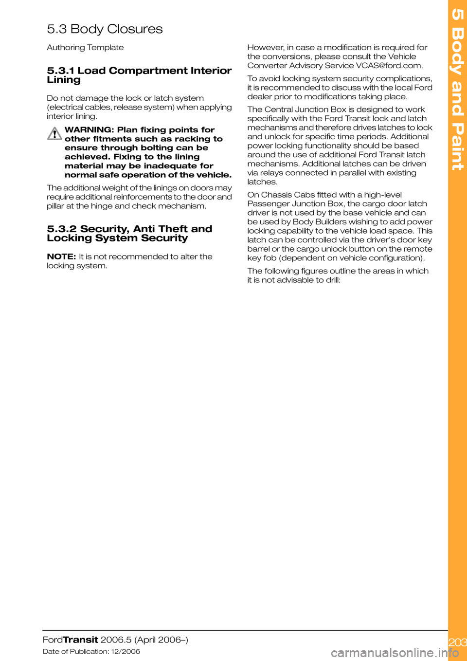
The Central Junction Box is designed to work
specifically with the Ford Transit lock and latch
mechanisms and therefore drives latches to lock
and unlock for specific time periods. Additional
power locking functionality should be based
around the use of additional Ford Transit latch
mechanisms. Additional latches can be driven
via relays connected in parallel with existing
latches.
On Chassis Cabs fitted with a high-level
Passenger Junction Box, the cargo door latch
driver is not used by the base vehicle and can
be used by Body Builders wishing to add power
locking capability to the vehicle load space. This
latch can be controlled via the driver's door key
barrel or the cargo unlock button on the remote
key fob (dependent on vehicle configuration).
The following figures outline the areas in which
it is not advisable to drill:
FordTransit 2006.5 (April 2006–)
Date of Publication: 12/2006
5 Body and Paint
203
Page 230 of 234

A
About This Manual................................................6
Accessory Drive..................................................77
Adding Connectors, Terminals and Wiring....
162
Additional 'Theatre Lighting' for rear of vehicle
interior...............................................................118
Additional External Lamps...............................116
Additional Ignition, Instrument Panel Illumination
and Air Conditioning On Signals...................124
Additional Internal Lamps ................................118
Additional Vehicle Signals / Features.............147
Aids for Vehicle Entry and Exit..........................33
Air Bags..............................................................218
Air Bag Supplemental Restraint System (SRS)..
218
Air Flow Restrictions...........................................76
Alternative Type Approval....................................7
Ancillary Equipment - Sub Frame Mounting....
228
Antenna Location...............................................24
Anti-Lock Control - Stability Assist..................65
Auxiliary Fuses, Fuse Box and Relays (Fuses -
Standard)..........................................................119
Auxiliary Heater Installation...............................76
Auxiliary Heater Systems..................................75
B
Back Panel Removal................................177, 214
Battery and Cables............................................98
Battery Information............................................98
Body....................................................................175
Body Closures..................................................203
Body Structures - General Information.........175
Body System - General
Information—Specifications.........................200
Brake Hoses General........................................62
Brake System.....................................................62
C
Cab Roof Removal...........................................214
Cab Van Floor....................................................185
CAN-Bus System Description and Interface....
90
Cellular Phone....................................................115
Center of Gravity ...............................................46
Central Junction Box (CJB)...............................91
Charge Balance Guidelines..............................97
Charging System...............................................95
Chassis Cab.......................................................179
Circit Diagram.....................................................94
Circuit Diagram...................................................93
Circuit Diagrams.................................................97
Climate Control System..................................106
Clutch...................................................................82
Commercial and Legal Aspects.........................7
Communications Network...............................90
Connectors........................................................133
Contact Corrosion............................................221
Contact Information.............................................9
Conversion Affect on Fuel Economy and
Performance.....................................................25
Conversion Affects on Parking Aids................33
Conversion Homologation...............................23
Conversion Type.................................................14
Corrosion Prevention.......................................221
Customer Connection Points.........................120
D
Drilling and Welding..............................................8
Driver's Standing Head Room........................214
Driver Field of View.............................................33
Driver Reach Zones...........................................33
Driveshaft.............................................................61
E
Electrical Conversions.......................................95
Electrically operated Door Mirrors..................117
Electrics for Tow bar........................................136
Electromagnetic Compatibility (EMC)............24
Electronic Engine Controls................................81
End of Life Vehicle (ELV) Directive...................26
Engine Cooling....................................................75
Engine..................................................................66
Engine Power Curves.......................................66
Engine RPM (Revs Per Minute) Speed
Controller..........................................................157
Engine Run Signal (D+ Alternative)................132
Exhaust Heat Shields.........................................86
Exhaust Pipes and Supports............................86
Exhaust System.................................................86
Extended Chassis Frame...............................226
Extensions and Optional Exhausts..................86
Exterior Lighting.................................................116
F
Fitting of Equipment Containing an Electric
Motor..................................................................97
Frame and Body Mounting............................222
Frame Drilling and Tube Reinforcing.............228
Front, Rear and Side Under-run Protection....
38
Front and Rear Brakes......................................64
Front End Accessory Drive 2.2l Diesel............79
Front End Accessory Drive 2.4l Diesel and 2.3l
Petrol...................................................................77
Front End Integrity for Cooling, Crash,
Aerodynamics and Lighting..........................198
Front Suspension...............................................58
Fuel System........................................................88
Fuses and Relays..............................................119
G
General........................................................62, 221
General Component Package Guidelines.....33
General Information and Specific Warnings....
95
General........................................................62, 221
General Product Safety Requirement...............7
Index
230
Page 231 of 234

Generator and Alternator...............................103
Glass, Frames and Mechanisms...................211
Ground Points..................................................140
H
Hardware—Specifications...............................43
Heated Seats...................................................210
Heated Windshield and Heated Rear Window.
213
Horn...................................................................108
How to Use This Manual....................................6
Hydraulic Brake Actuation...............................64
Hydraulic Lifting Equipment for Van, Bus, Kombi
and Chassis Cab...........................................186
I
Important Safety Instructions............................6
Information and Entertainment System -
General Information—Specifications...........112
Installation and Routing Guides.....................134
Instrument Cluster...........................................107
Integrated Bodies and Conversions.............177
Interior Lighting.................................................118
Introduction..........................................................6
J
Jacking................................................................27
K
Kerb Mass Data.................................................62
L
Lamps for Wide Vehicles.................................117
Lamps – Front and Rear Fog Lights..............117
Lamps – Hazard / Direction Indication..........117
Legal and Vehicle Type Approval......................7
Legal Obligations and Liabilities.........................7
Legislation.........................................................109
Lifting...................................................................29
Load Apportioning Valves................................64
Load Compartment Interior Lining...............203
Load Distribution—Specifications...................44
Load Distribution Calculations - Driver and
Passenger Weight Distribution.....................44
M
Manual Transmission........................................83
Minimum Requirements for Brake system and
Load Apportioning Valves ...............................8
Mirrors for Wide Vehicles...............................208
Module Communications
Network—Specifications................................94
Mounting Points and Tubing.........................222
N
Noise, Vibration and Harshness (NVH)...........31
Non Standard Rear Chassis Frame Extension.
226
P
Package and Ergonomics—Specifications....
34
Package and Ergonomics...............................33
Painting Road Wheels..............................60, 221
Parking Brake....................................................63
Partitions (Bulkhead) - Driver and Front
Passenger(s) Protection on Van, Bus and
Kombi..............................................................192
Possible Accessories.......................................113
Power Management Settings.........................95
Power Take Off...................................................61
Product Liability....................................................8
R
Racking Systems.............................................194
Radio Connector..............................................112
Rear Anti-Roll Bar..............................................59
Rear Seat Fixings Positions - Kombi............209
Rear Suspension...............................................59
Rear View Mirrors...........................................208
Rear Windows..................................................211
Recommended Main Dimensions.................34
Recommended Main Load Area Dimensions
for Bulkhead with Depression Driver Side....
39
Recommended Main Load Area Dimensions
for Bulkhead with Full Depression................40
Recommended Main Load Area Dimensions
for Double Cab In Van Bulkhead...................41
Recommended Nominal Body Lengths for
Chassis Cab models......................................36
Relays and Switches.......................................127
Relocated Parking Brake Lever......................63
Repairing Damaged Paint..............................221
Restraints System...............................................8
Reversing Lamps.............................................116
Road Safety..........................................................8
Roof Opening Panel........................................214
Roof Racks.......................................................216
Roof Ventilation................................................215
S
Safety Belt System.........................................220
Seats.................................................................209
Security, Anti Theft and Locking System
Security ..........................................................203
Self-Supporting Body Structure...................224
Spare Tire Access and Mounting.................229
Spare wheel.......................................................60
Special Conversions........................................131
Special Vehicle Option Auxiliary Fuse Box....
121
Index
231