buttons FORD TRANSIT 2016 5.G Owners Manual
[x] Cancel search | Manufacturer: FORD, Model Year: 2016, Model line: TRANSIT, Model: FORD TRANSIT 2016 5.GPages: 411, PDF Size: 5.65 MB
Page 54 of 411
CREATING A MYKEY
You can program a MyKey using the
information display control on the steering
wheel. See Information Displays (page
82).
Insert the key you want to program into the
ignition and switch the ignition on.
Press the left arrow button to access the main menu and scroll to: Action and Description
Message
Press the
OK button.
Settings
Press the
OK button.
MyKey
When prompted, hold the OK button until you see a message
informing you to label this key as a MyKey. The key will be
restricted at your vehicle's next start.
Create MyKey
Make sure you label the key so you can distinguish it from the
admin keys.
You can also program configurable settings for the key(s).
Refer to the following Programming/Changing Configur-
able Settings
.
Programming/Changing
Configurable Settings
Switch the ignition on using an admin key
or fob.
Use the information display to access the configurable MyKey settings, scroll to: Action and Description
Message
Press the
OK button.
Settings
Use the up and down arrow buttons to scroll to a configurable
feature.
MyKey
Press the
OK or right arrow button to make a selection.
Choose your applicable setting.
Note: You can clear or change your MyKey settings at any time during the same key cycle
as you created the MyKey. Once you switch the ignition off you will need an admin key to
change or clear your MyKey settings.
51
Transit (TTH) Canada/United States of America, enUSA, First Printing MyKey
™
(If Equipped)
Page 78 of 411
Auto-Dimming Mirror (If Equipped)
Note: Do not block the sensors on the front
and back of the mirror. Mirror performance
may be affected. A rear center passenger or
raised rear center head restraint may also
block light from reaching the sensor.
The mirror will dim automatically to reduce
glare when bright lights are detected from
behind your vehicle. It will automatically
return to normal reflection when you select
reverse gear to make sure you have a clear
view when backing up.
REAR QUARTER WINDOWS
Opening the Rear Windows
(If
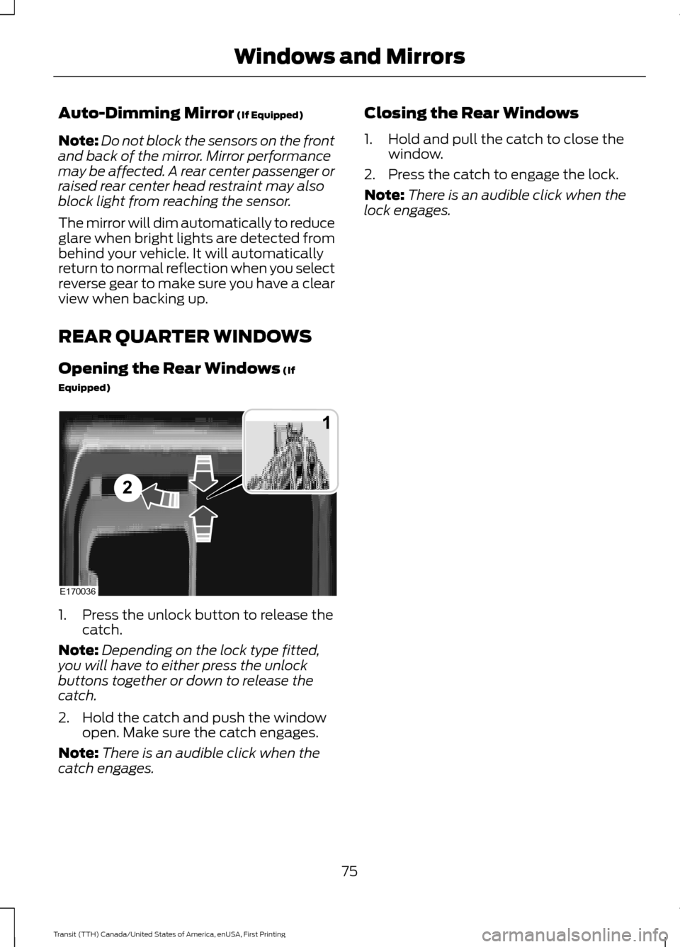
Equipped) 1. Press the unlock button to release the
catch.
Note: Depending on the lock type fitted,
you will have to either press the unlock
buttons together or down to release the
catch.
2. Hold the catch and push the window open. Make sure the catch engages.
Note: There is an audible click when the
catch engages. Closing the Rear Windows
1. Hold and pull the catch to close the
window.
2. Press the catch to engage the lock.
Note: There is an audible click when the
lock engages.
75
Transit (TTH) Canada/United States of America, enUSA, First Printing Windows and MirrorsE170036
1
2
Page 85 of 411
GENERAL INFORMATION
WARNING
Driving while distracted can result in
loss of vehicle control, crash and
injury. We strongly recommend that
you use extreme caution when using any
device that may take your focus off the
road. Your primary responsibility is the safe
operation of your vehicle. We recommend
against the use of any hand-held device
while driving and encourage the use of
voice-operated systems when possible.
Make sure you are aware of all applicable
local laws that may affect the use of
electronic devices while driving. You can control various systems on your
vehicle using the information display
controls on the steering wheel.
The information display shows the
corresponding information.
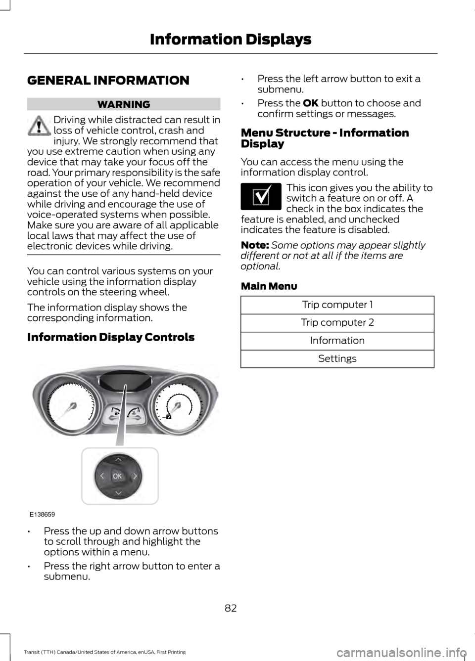
Information Display Controls
•
Press the up and down arrow buttons
to scroll through and highlight the
options within a menu.
• Press the right arrow button to enter a
submenu. •
Press the left arrow button to exit a
submenu.
• Press the OK button to choose and
confirm settings or messages.
Menu Structure - Information
Display
You can access the menu using the
information display control. This icon gives you the ability to
switch a feature on or off. A
check in the box indicates the
feature is enabled, and unchecked
indicates the feature is disabled.
Note: Some options may appear slightly
different or not at all if the items are
optional.
Main Menu Trip computer 1
Trip computer 2 InformationSettings
82
Transit (TTH) Canada/United States of America, enUSA, First Printing Information DisplaysE138659 E204495
Page 89 of 411
System Check
All active warnings will display first if
applicable. The system check menu may
appear different based upon equipment
options and current vehicle status. Use the
up and down arrow buttons to scroll
through the list. See Information
Messages (page 87).
TRIP COMPUTER
Resetting the Trip Computer
Press and hold
OK on the current screen
to reset the respective trip, distance, time
and average fuel consumption information.
All Values
Indicates all the respective trip, distance,
time and average fuel consumption
information.
Average Fuel Consumption
Indicates the average fuel consumption
since the function was last reset. Distance to Empty
Indicates the approximate distance your
vehicle will travel on the fuel remaining in
the tank. Changes in driving pattern may
cause the value to vary.
Outside Air Temperature
Shows the outside air temperature.
Trip Odometer
Registers the distance traveled of
individual journeys.
Trip Timer
Registers the elapsed time of individual
journeys or the total time since the function
was last reset.
Digital Speedometer
Provides a digital display of the current
vehicle speed.
PERSONALIZED SETTINGS
Measure Units
You can choose personalized settings
using the information display control on
the steering wheel.
See Information
Displays (page 82).
To swap between imperial and metric units, scroll to: Action and Description
Message
Press the
OK button.
Display
Choose your applicable setting. Press the
OK button.
Measure unit
Swapping between imperial and metric units will affect the
following displays:
•Average fuel consumption.
• Distance to empty.
• Odometer.
86
Transit (TTH) Canada/United States of America, enUSA, First Printing Information Displays
Page 98 of 411
Side Window Defogging in Cold
Weather
•
Adjust the air distribution control to the
instrument panel and windshield air
vents positions.
• Press the A/C button.
• Adjust the temperature control to the
desired setting.
• Adjust the fan speed to the highest
setting.
• Direct the instrument panel side air
vents toward the side windows.
• Close the instrument panel vents. Maximum Cooling Performance in
Instrument Panel or Instrument
Panel and Footwell Positions
•
Adjust the temperature control to the
lowest setting.
• Press the A/C and recirculated air
buttons.
• Adjust the fan speed to the highest
setting initially and then adjust it to suit
the desired comfort level.
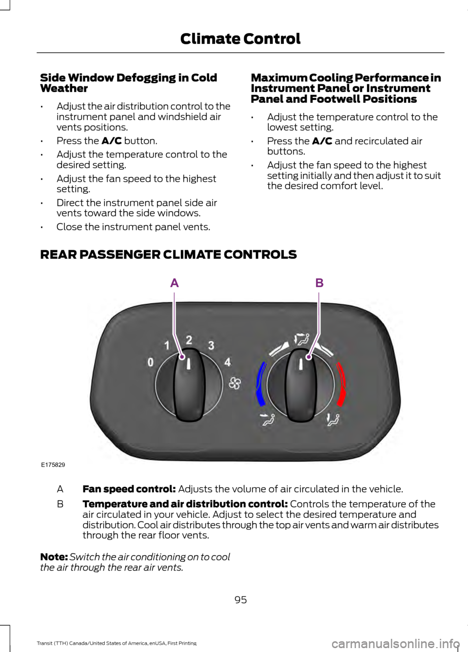
REAR PASSENGER CLIMATE CONTROLS Fan speed control:
Adjusts the volume of air circulated in the vehicle.
A
Temperature and air distribution control:
Controls the temperature of the
air circulated in your vehicle. Adjust to select the desired temperature and
distribution. Cool air distributes through the top air vents and warm air distributes
through the rear floor vents.
B
Note: Switch the air conditioning on to cool
the air through the rear air vents.
95
Transit (TTH) Canada/United States of America, enUSA, First Printing Climate ControlE175829
AB
Page 101 of 411
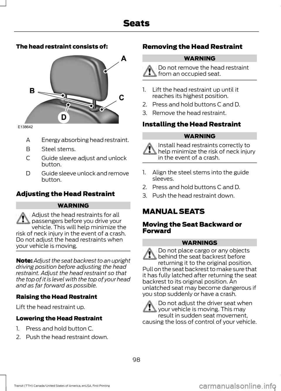
The head restraint consists of:
Energy absorbing head restraint.
A
Steel stems.
B
Guide sleeve adjust and unlock
button.
C
Guide sleeve unlock and remove
button.
D
Adjusting the Head Restraint WARNING
Adjust the head restraints for all
passengers before you drive your
vehicle. This will help minimize the
risk of neck injury in the event of a crash.
Do not adjust the head restraints when
your vehicle is moving. Note:
Adjust the seat backrest to an upright
driving position before adjusting the head
restraint. Adjust the head restraint so that
the top of it is level with the top of your head
and as far forward as possible.
Raising the Head Restraint
Lift the head restraint up.
Lowering the Head Restraint
1. Press and hold button C.
2. Push the head restraint down. Removing the Head Restraint WARNING
Do not remove the head restraint
from an occupied seat.
1. Lift the head restraint up until it
reaches its highest position.
2. Press and hold buttons C and D.
3. Remove the head restraint.
Installing the Head Restraint WARNING
Install head restraints correctly to
help minimize the risk of neck injury
in the event of a crash.
1. Align the steel stems into the guide
sleeves.
2. Press and hold buttons C and D.
3. Push the head restraint down.
MANUAL SEATS
Moving the Seat Backward or
Forward WARNINGS
Do not place cargo or any objects
behind the seat backrest before
returning it to the original position.
Pull on the seat backrest to make sure that
it has fully latched after returning the seat
backrest to its original position. An
unlatched seat may become dangerous if
you stop suddenly or have a crash. Do not adjust the driver seat when
your vehicle is moving. This may
result in sudden seat movement,
causing the loss of control of your vehicle.
98
Transit (TTH) Canada/United States of America, enUSA, First Printing SeatsE138642
Page 140 of 411
WARNINGS
Apply the parking brake, shift the
gearshift lever to park (P) and switch
the ignition off before leaving your
vehicle. Make sure that the gearshift lever
fully latches into position. When the gearshift lever is in this position,
it will lock the transmission. The engine
does not transmit power to the driven
wheels. You can start the engine with the
gearshift lever in this position.
Note:
A warning tone will sound if you open
the driver door and you have not shifted the
gearshift lever to park (P).
Reverse (R) WARNINGS
Do not shift the gearshift lever to
reverse (R) when your vehicle is
moving. This can cause damage to
the transmission not covered by the vehicle
warranty, and can result in a crash or
serious injury. Always come to a complete stop
before shifting the gearshift lever out
of reverse (R).
Shift the gearshift lever to reverse (R) to
allow your vehicle to move backward.
Neutral (N)
When the gearshift lever is in this position,
the transmission does not lock. The engine
does not transmit power to the driven
wheels. You can start the engine with the
gearshift lever in this position.
Drive (D)
Shift the gearshift lever to drive (D) to
allow your vehicle to move forward and
shift automatically through the forward
gears. The transmission shifts to the appropriate
gear for optimum performance based on
ambient temperature, road gradient,
vehicle load and your input.
Note:
A shift will occur only when your
vehicle speed and the engine speed are
appropriate.
Note: You can temporarily override the
selected gear by pressing the + or - buttons
on the side of the gearshift lever.
Manual (M) WARNING
Do not hold the + or - buttons
permanently in. Shift the gearshift lever to manual (M) to
allow your vehicle to move forward and
allow you to shift manually through the
forward gears. Press the
+ or - buttons on
the side of the gearshift lever to shift
manually through the forward gears. The
instrument cluster will display the selected
gear, and a shift indicator arrow to assist
optimum shifting.
• Press the
+ button to upshift.
• Press the
- button to downshift.
You can skip gears by pressing a button
repeatedly at short intervals.
Upshift at the recommended shift
speeds according to the following
chart: Upshifts when accelerating (recom-
mended for best fuel economy)
Vehicle speed mph( km/h):
Upshift from:
15 (24)
1 - 2
25 (40)
2 - 3
40 (64)
3 - 4
137
Transit (TTH) Canada/United States of America, enUSA, First Printing Transmission
Page 174 of 411
Integrated Trailer Brake Controller
WARNING
The Ford trailer brake controller has
been verified to be compatible with
trailers having electric-actuated
drum brakes (one to four axles) and
electric-over-hydraulic brakes. It will not
turn on the hydraulic surge-style trailer
brakes. It is the responsibility of the
customer to make sure that the trailer
brakes are adjusted appropriately,
functioning normally and all electric
connections are correctly made. Failure to
do so may result in loss of vehicle control,
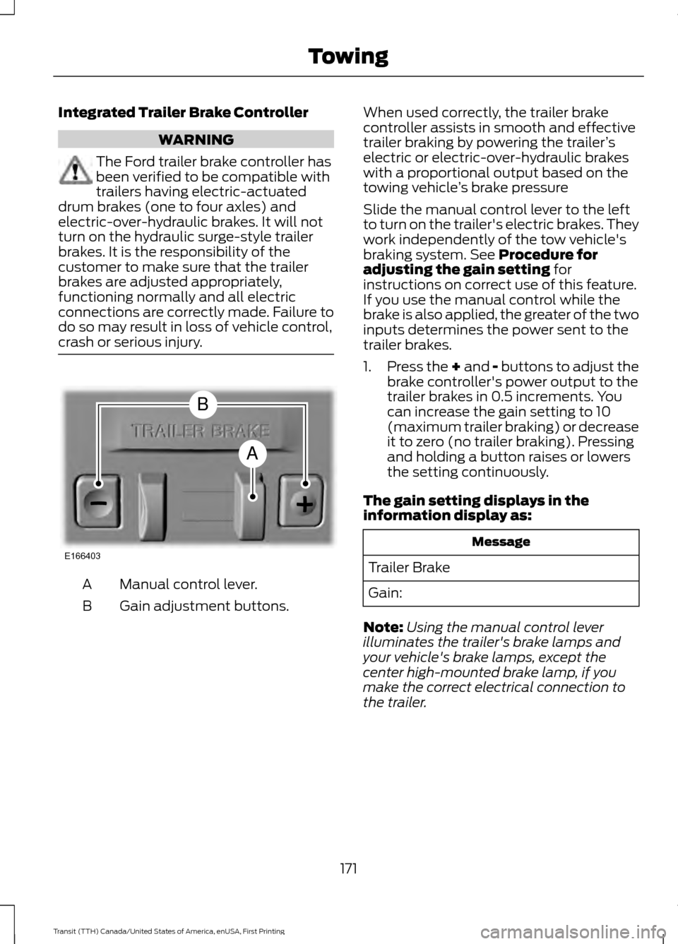
crash or serious injury. Manual control lever.
A
Gain adjustment buttons.
B When used correctly, the trailer brake
controller assists in smooth and effective
trailer braking by powering the trailer
’s
electric or electric-over-hydraulic brakes
with a proportional output based on the
towing vehicle ’s brake pressure
Slide the manual control lever to the left
to turn on the trailer's electric brakes. They
work independently of the tow vehicle's
braking system. See Procedure for
adjusting the gain setting for
instructions on correct use of this feature.
If you use the manual control while the
brake is also applied, the greater of the two
inputs determines the power sent to the
trailer brakes.
1. Press the + and - buttons to adjust the
brake controller's power output to the
trailer brakes in 0.5 increments. You
can increase the gain setting to 10
(maximum trailer braking) or decrease
it to zero (no trailer braking). Pressing
and holding a button raises or lowers
the setting continuously.
The gain setting displays in the
information display as: Message
Trailer Brake
Gain:
Note: Using the manual control lever
illuminates the trailer's brake lamps and
your vehicle's brake lamps, except the
center high-mounted brake lamp, if you
make the correct electrical connection to
the trailer.
171
Transit (TTH) Canada/United States of America, enUSA, First Printing TowingE166403
A
B
Page 175 of 411
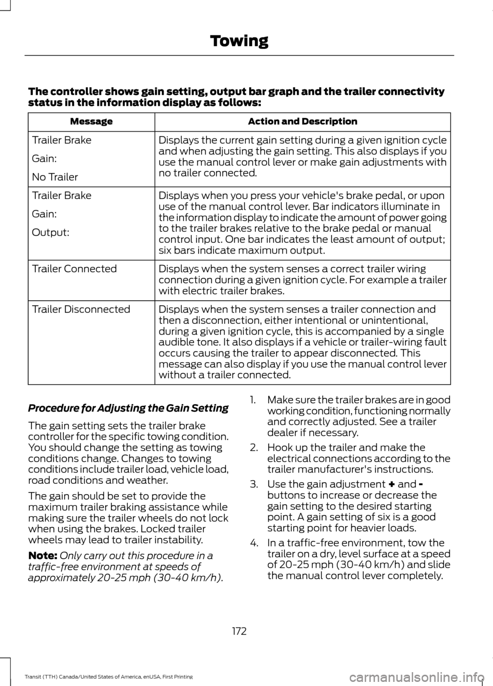
The controller shows gain setting, output bar graph and the trailer connectivity
status in the information display as follows:
Action and Description
Message
Displays the current gain setting during a given ignition cycle
and when adjusting the gain setting. This also displays if you
use the manual control lever or make gain adjustments with
no trailer connected.
Trailer Brake
Gain:
No Trailer
Displays when you press your vehicle's brake pedal, or upon
use of the manual control lever. Bar indicators illuminate in
the information display to indicate the amount of power going
to the trailer brakes relative to the brake pedal or manual
control input. One bar indicates the least amount of output;
six bars indicate maximum output.
Trailer Brake
Gain:
Output:
Displays when the system senses a correct trailer wiring
connection during a given ignition cycle. For example a trailer
with electric trailer brakes.
Trailer Connected
Displays when the system senses a trailer connection and
then a disconnection, either intentional or unintentional,
during a given ignition cycle, this is accompanied by a single
audible tone. It also displays if a vehicle or trailer-wiring fault
occurs causing the trailer to appear disconnected. This
message can also display if you use the manual control lever
without a trailer connected.
Trailer Disconnected
Procedure for Adjusting the Gain Setting
The gain setting sets the trailer brake
controller for the specific towing condition.
You should change the setting as towing
conditions change. Changes to towing
conditions include trailer load, vehicle load,
road conditions and weather.
The gain should be set to provide the
maximum trailer braking assistance while
making sure the trailer wheels do not lock
when using the brakes. Locked trailer
wheels may lead to trailer instability.
Note: Only carry out this procedure in a
traffic-free environment at speeds of
approximately 20-25 mph (30-40 km/h). 1.
Make sure the trailer brakes are in good
working condition, functioning normally
and correctly adjusted. See a trailer
dealer if necessary.
2. Hook up the trailer and make the electrical connections according to the
trailer manufacturer's instructions.
3. Use the gain adjustment + and -
buttons to increase or decrease the
gain setting to the desired starting
point. A gain setting of six is a good
starting point for heavier loads.
4. In a traffic-free environment, tow the trailer on a dry, level surface at a speed
of 20-25 mph (30-40 km/h) and slide
the manual control lever completely.
172
Transit (TTH) Canada/United States of America, enUSA, First Printing Towing
Page 300 of 411
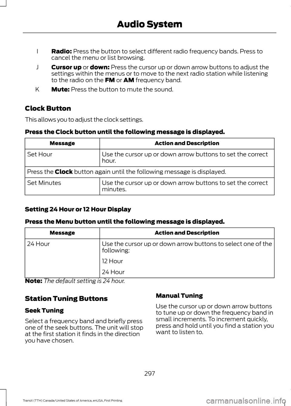
Radio: Press the button to select different radio frequency bands. Press to
cancel the menu or list browsing.
I
Cursor up
or down: Press the cursor up or down arrow buttons to adjust the
settings within the menus or to move to the next radio station while listening
to the radio on the
FM or AM frequency band.
J
Mute:
Press the button to mute the sound.
K
Clock Button
This allows you to adjust the clock settings.
Press the
Clock button until the following message is displayed. Action and Description
Message
Use the cursor up or down arrow buttons to set the correct
hour.
Set Hour
Press the
Clock button again until the following message is displayed.
Use the cursor up or down arrow buttons to set the correct
minutes.
Set Minutes
Setting 24 Hour or 12 Hour Display
Press the
Menu button until the following message is displayed. Action and Description
Message
Use the cursor up or down arrow buttons to select one of the
following:
24 Hour
12 Hour
24 Hour
Note: The default setting is 24 hour.
Station Tuning Buttons
Seek Tuning
Select a frequency band and briefly press
one of the seek buttons. The unit will stop
at the first station it finds in the direction
you have chosen. Manual Tuning
Use the cursor up or down arrow buttons
to tune up or down the frequency band in
small increments. To increment quickly,
press and hold until you find a station you
want to listen to.
297
Transit (TTH) Canada/United States of America, enUSA, First Printing Audio System