FORD TRANSIT CONNECT 2015 2.G Owners Manual
Manufacturer: FORD, Model Year: 2015, Model line: TRANSIT CONNECT, Model: FORD TRANSIT CONNECT 2015 2.GPages: 428, PDF Size: 6.27 MB
Page 141 of 428
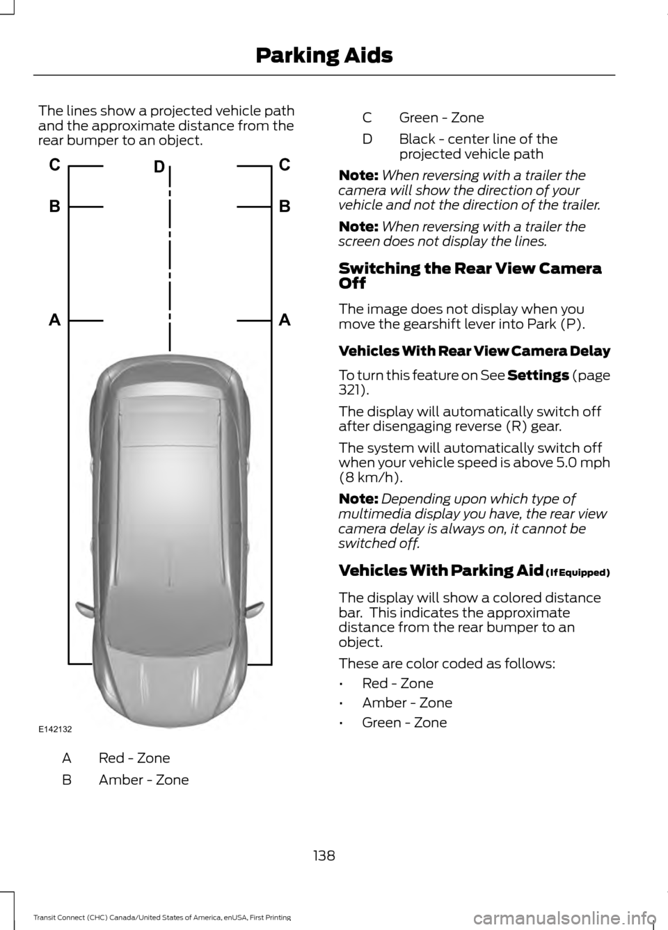
The lines show a projected vehicle path
and the approximate distance from the
rear bumper to an object.
Red - Zone
A
Amber - Zone
B Green - Zone
C
Black - center line of the
projected vehicle path
D
Note: When reversing with a trailer the
camera will show the direction of your
vehicle and not the direction of the trailer.
Note: When reversing with a trailer the
screen does not display the lines.
Switching the Rear View Camera
Off
The image does not display when you
move the gearshift lever into Park (P).
Vehicles With Rear View Camera Delay
To turn this feature on See Settings (page
321).
The display will automatically switch off
after disengaging reverse (R) gear.
The system will automatically switch off
when your vehicle speed is above 5.0 mph
(8 km/h)
.
Note: Depending upon which type of
multimedia display you have, the rear view
camera delay is always on, it cannot be
switched off.
Vehicles With Parking Aid
(If Equipped)
The display will show a colored distance
bar. This indicates the approximate
distance from the rear bumper to an
object.
These are color coded as follows:
• Red - Zone
• Amber - Zone
• Green - Zone
138
Transit Connect (CHC) Canada/United States of America, enUSA, First Printing Parking AidsE142132A B C
A B C
D
Page 142 of 428
PRINCIPLE OF OPERATION
Cruise control lets you maintain a set
speed without keeping your foot on the
accelerator pedal. You can use cruise
control when your vehicle speed is greater
than 20 mph (30 km/h).
USING CRUISE CONTROL WARNINGS
Do not use cruise control in heavy
traffic, on winding roads or when the
road surface is slippery. This could
result in loss of vehicle control, serious
injury or death. When you are going downhill, your
vehicle speed may increase above
the set speed. The system will not
apply the brakes. Change down a gear to
assist the system in maintaining the set
speed. Failure to do so could result in loss
of vehicle control, serious injury or death. Note:
Cruise control will disengage if your
vehicle speed decreases more than 10 mph
(16 km/h) below your set speed while
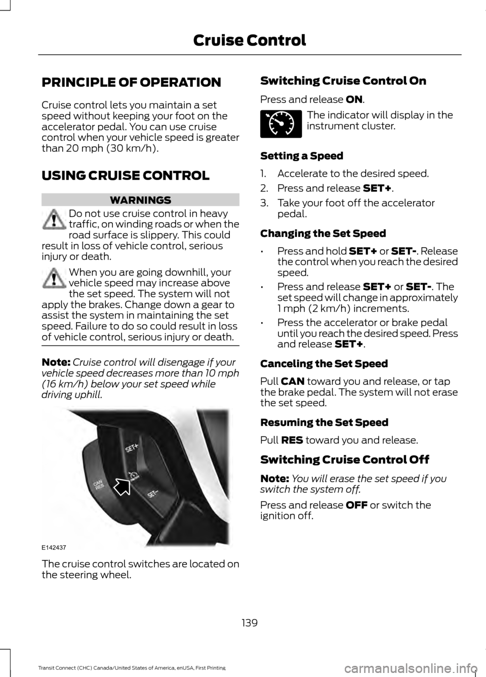
driving uphill. The cruise control switches are located on
the steering wheel. Switching Cruise Control On
Press and release
ON. The indicator will display in the
instrument cluster.
Setting a Speed
1. Accelerate to the desired speed.
2. Press and release
SET+.
3. Take your foot off the accelerator pedal.
Changing the Set Speed
• Press and hold SET+ or SET-. Release
the control when you reach the desired
speed.
• Press and release
SET+ or SET-. The
set speed will change in approximately
1 mph (2 km/h) increments.
• Press the accelerator or brake pedal
until you reach the desired speed. Press
and release
SET+.
Canceling the Set Speed
Pull
CAN toward you and release, or tap
the brake pedal. The system will not erase
the set speed.
Resuming the Set Speed
Pull
RES toward you and release.
Switching Cruise Control Off
Note: You will erase the set speed if you
switch the system off.
Press and release
OFF or switch the
ignition off.
139
Transit Connect (CHC) Canada/United States of America, enUSA, First Printing Cruise ControlE142437 E71340
Page 143 of 428
STEERING
Electric Power Steering
WARNING
The electric power steering system
has diagnostic checks that
continuously monitor the system. If
a fault is detected, a message displays in
the information display. Stop your vehicle
as soon as it is safe to do so. Switch the
ignition off. After at least 10 seconds,
switch the ignition on and watch the
information display for a steering system
warning message. If a steering system
warning message returns, have the system
checked by an authorized dealer. Your vehicle has an electric power steering
system. There is no fluid reservoir. No
maintenance is required.
If your vehicle loses electrical power while
you are driving, electric power steering
assistance is lost. The steering system still
operates and you can steer your vehicle
manually. Manually steering your vehicle
requires more effort.
Extreme continuous steering may increase
the effort required for you to steer your
vehicle. This increased effort prevents
overheating and permanent damage to
the steering system. You do not lose the
ability to steer your vehicle manually.
Typical steering and driving maneuvers
allow the system to cool and return to
normal operation.
Steering Tips
If the steering wanders or pulls, check for:
•
Correct tire pressures.
• Uneven tire wear.
• Loose or worn suspension
components. •
Loose or worn steering components.
• Improper vehicle alignment.
Note: A high crown in the road or high
crosswinds may also make the steering
seem to wander or pull.
Adaptive Learning
The electronic power steering system
adaptive learning helps correct road
irregularities and improves overall handling
and steering feel. It communicates with
the brake system to help operate
advanced stability control and accident
avoidance systems. Additionally, whenever
the battery is disconnected or a new
battery installed, you must drive your
vehicle a short distance before the system
relearns the strategy and reactivates all
systems.
140
Transit Connect (CHC) Canada/United States of America, enUSA, First Printing Driving Aids
Page 144 of 428
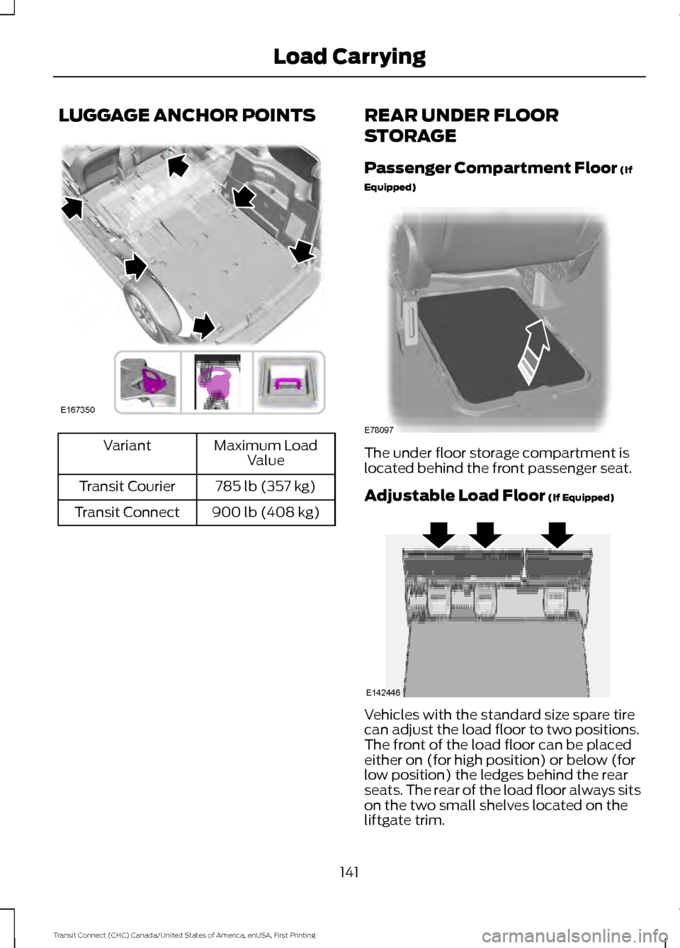
LUGGAGE ANCHOR POINTS
Maximum Load
Value
Variant
785 lb (357 kg)
Transit Courier
900 lb (408 kg)
Transit Connect REAR UNDER FLOOR
STORAGE
Passenger Compartment Floor (If
Equipped) The under floor storage compartment is
located behind the front passenger seat.
Adjustable Load Floor
(If Equipped)
Vehicles with the standard size spare tire
can adjust the load floor to two positions.
The front of the load floor can be placed
either on (for high position) or below (for
low position) the ledges behind the rear
seats. The rear of the load floor always sits
on the two small shelves located on the
liftgate trim.
141
Transit Connect (CHC) Canada/United States of America, enUSA, First Printing Load CarryingE167350 E78097 E142446
Page 145 of 428
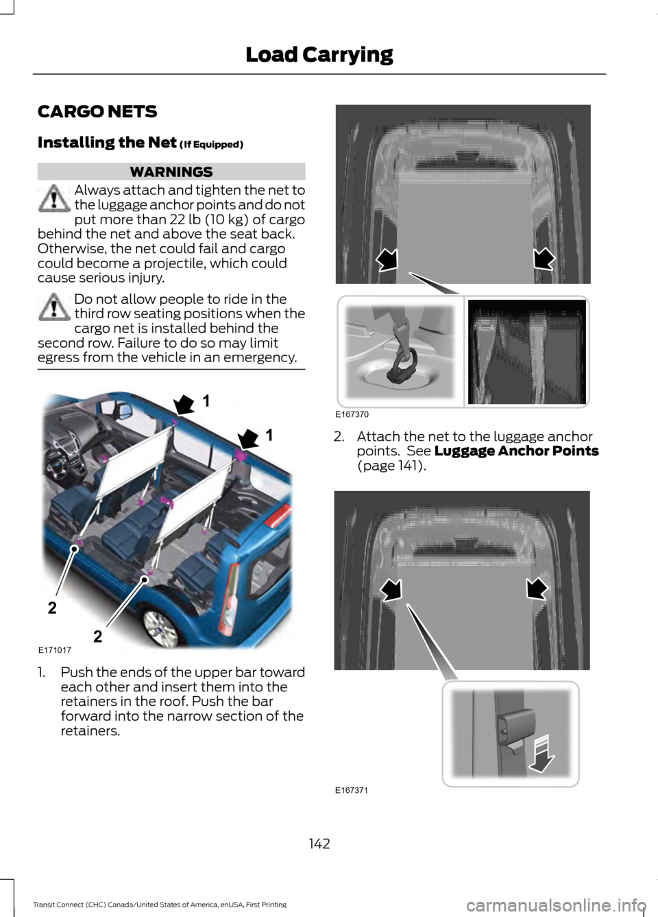
CARGO NETS
Installing the Net (If Equipped)
WARNINGS
Always attach and tighten the net to
the luggage anchor points and do not
put more than
22 lb (10 kg) of cargo
behind the net and above the seat back.
Otherwise, the net could fail and cargo
could become a projectile, which could
cause serious injury. Do not allow people to ride in the
third row seating positions when the
cargo net is installed behind the
second row. Failure to do so may limit
egress from the vehicle in an emergency. 1.
Push the ends of the upper bar toward
each other and insert them into the
retainers in the roof. Push the bar
forward into the narrow section of the
retainers. 2. Attach the net to the luggage anchor
points. See
Luggage Anchor Points
(page 141). 142
Transit Connect (CHC) Canada/United States of America, enUSA, First Printing Load CarryingE1710171
12
2 E167370 E167371
Page 146 of 428
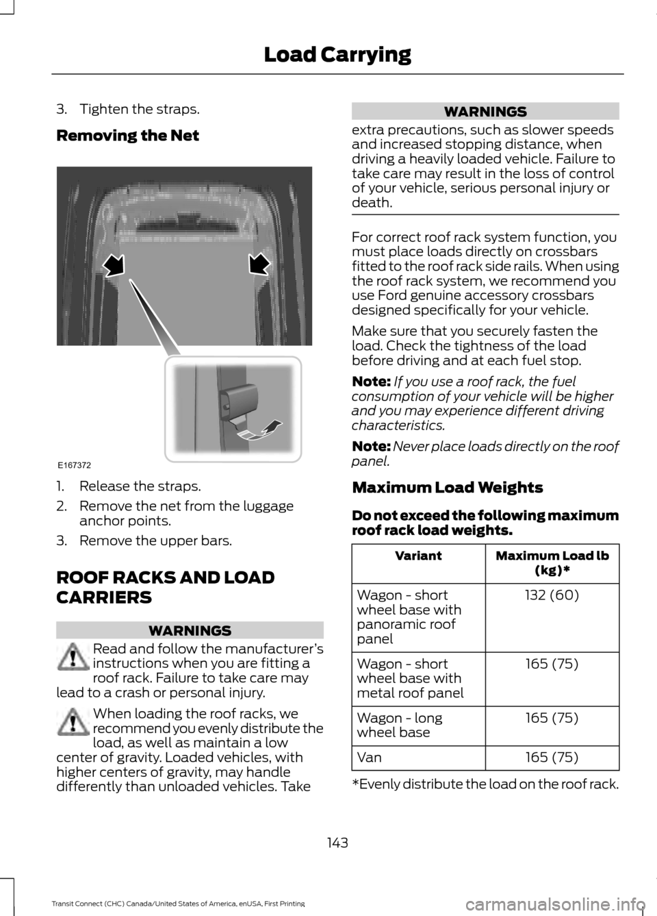
3. Tighten the straps.
Removing the Net
1. Release the straps.
2. Remove the net from the luggage
anchor points.
3. Remove the upper bars.
ROOF RACKS AND LOAD
CARRIERS WARNINGS
Read and follow the manufacturer
’s
instructions when you are fitting a
roof rack. Failure to take care may
lead to a crash or personal injury. When loading the roof racks, we
recommend you evenly distribute the
load, as well as maintain a low
center of gravity. Loaded vehicles, with
higher centers of gravity, may handle
differently than unloaded vehicles. Take WARNINGS
extra precautions, such as slower speeds
and increased stopping distance, when
driving a heavily loaded vehicle. Failure to
take care may result in the loss of control
of your vehicle, serious personal injury or
death. For correct roof rack system function, you
must place loads directly on crossbars
fitted to the roof rack side rails. When using
the roof rack system, we recommend you
use Ford genuine accessory crossbars
designed specifically for your vehicle.
Make sure that you securely fasten the
load. Check the tightness of the load
before driving and at each fuel stop.
Note:
If you use a roof rack, the fuel
consumption of your vehicle will be higher
and you may experience different driving
characteristics.
Note: Never place loads directly on the roof
panel.
Maximum Load Weights
Do not exceed the following maximum
roof rack load weights. Maximum Load lb
(kg)*
Variant
132 (60)
Wagon - short
wheel base with
panoramic roof
panel
165 (75)
Wagon - short
wheel base with
metal roof panel
165 (75)
Wagon - long
wheel base
165 (75)
Van
*Evenly distribute the load on the roof rack.
143
Transit Connect (CHC) Canada/United States of America, enUSA, First Printing Load CarryingE167372
Page 147 of 428
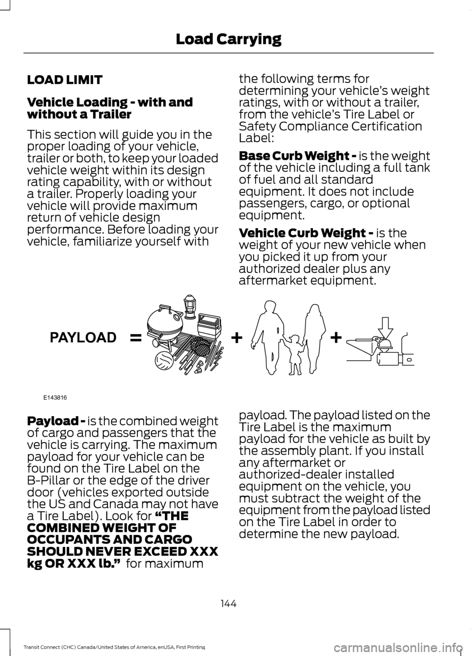
LOAD LIMIT
Vehicle Loading - with and
without a Trailer
This section will guide you in the
proper loading of your vehicle,
trailer or both, to keep your loaded
vehicle weight within its design
rating capability, with or without
a trailer. Properly loading your
vehicle will provide maximum
return of vehicle design
performance. Before loading your
vehicle, familiarize yourself with
the following terms for
determining your vehicle
’s weight
ratings, with or without a trailer,
from the vehicle ’s Tire Label or
Safety Compliance Certification
Label:
Base Curb Weight - is the weight
of the vehicle including a full tank
of fuel and all standard
equipment. It does not include
passengers, cargo, or optional
equipment.
Vehicle Curb Weight -
is the
weight of your new vehicle when
you picked it up from your
authorized dealer plus any
aftermarket equipment. Payload -
is the combined weight
of cargo and passengers that the
vehicle is carrying. The maximum
payload for your vehicle can be
found on the Tire Label on the
B-Pillar or the edge of the driver
door (vehicles exported outside
the US and Canada may not have
a Tire Label). Look for
“THE
COMBINED WEIGHT OF
OCCUPANTS AND CARGO
SHOULD NEVER EXCEED XXX
kg OR XXX lb. ” for maximum payload. The payload listed on the
Tire Label is the maximum
payload for the vehicle as built by
the assembly plant. If you install
any aftermarket or
authorized-dealer installed
equipment on the vehicle, you
must subtract the weight of the
equipment from the payload listed
on the Tire Label in order to
determine the new payload.
144
Transit Connect (CHC) Canada/United States of America, enUSA, First Printing Load CarryingE143816PAYLOAD
Page 148 of 428
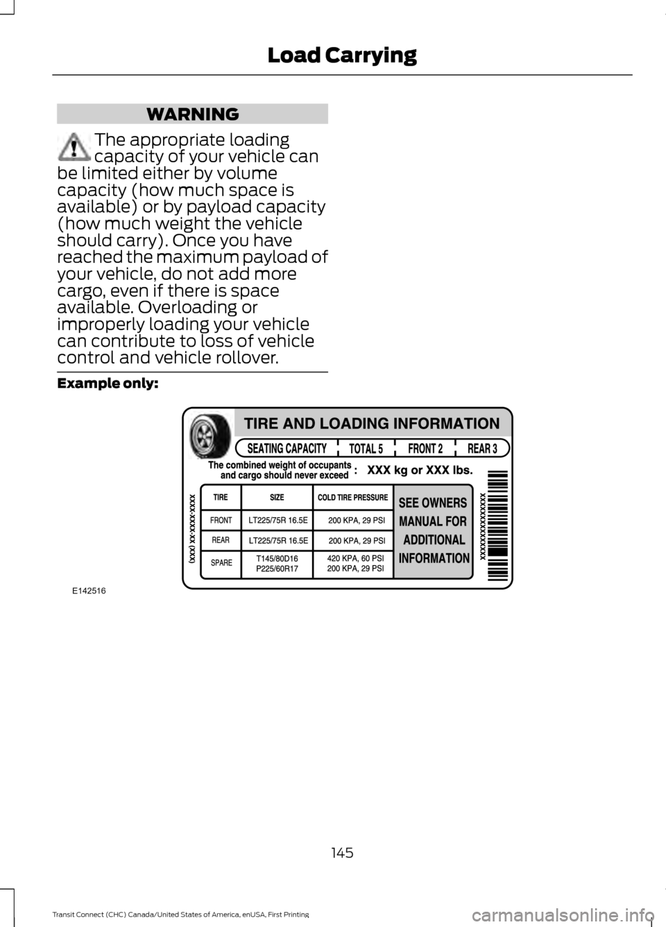
WARNING
The appropriate loading
capacity of your vehicle can
be limited either by volume
capacity (how much space is
available) or by payload capacity
(how much weight the vehicle
should carry). Once you have
reached the maximum payload of
your vehicle, do not add more
cargo, even if there is space
available. Overloading or
improperly loading your vehicle
can contribute to loss of vehicle
control and vehicle rollover. Example only:
145
Transit Connect (CHC) Canada/United States of America, enUSA, First Printing Load CarryingE142516
Page 149 of 428
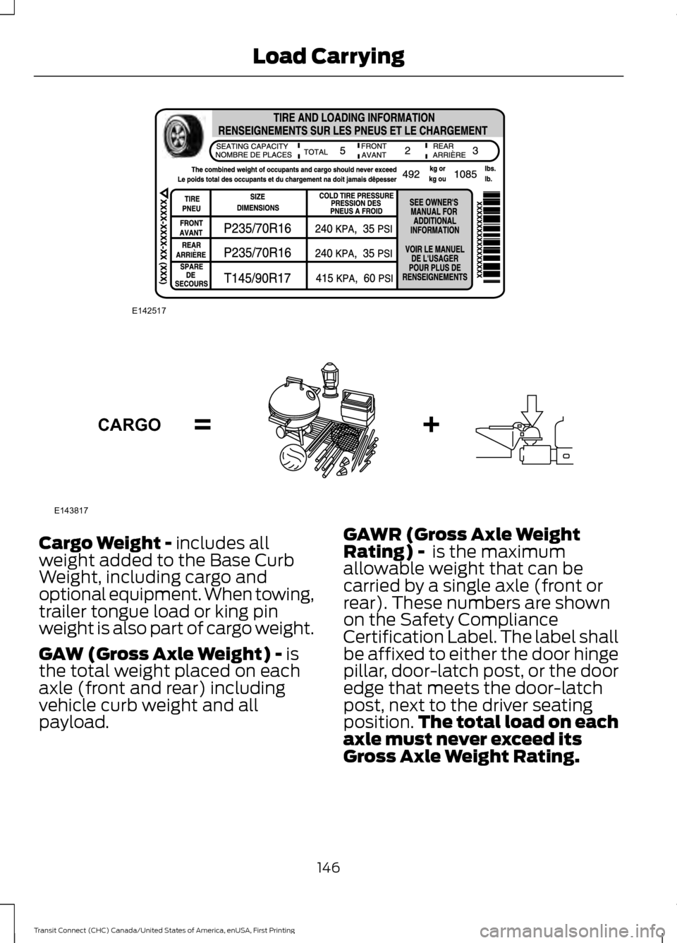
Cargo Weight - includes all
weight added to the Base Curb
Weight, including cargo and
optional equipment. When towing,
trailer tongue load or king pin
weight is also part of cargo weight.
GAW (Gross Axle Weight) -
is
the total weight placed on each
axle (front and rear) including
vehicle curb weight and all
payload. GAWR (Gross Axle Weight
Rating) -
is the maximum
allowable weight that can be
carried by a single axle (front or
rear). These numbers are shown
on the Safety Compliance
Certification Label. The label shall
be affixed to either the door hinge
pillar, door-latch post, or the door
edge that meets the door-latch
post, next to the driver seating
position. The total load on each
axle must never exceed its
Gross Axle Weight Rating.
146
Transit Connect (CHC) Canada/United States of America, enUSA, First Printing Load CarryingE142517 E143817CARGO
Page 150 of 428
Note:
For trailer towing
information refer to the RV and
Trailer Towing Guide available at
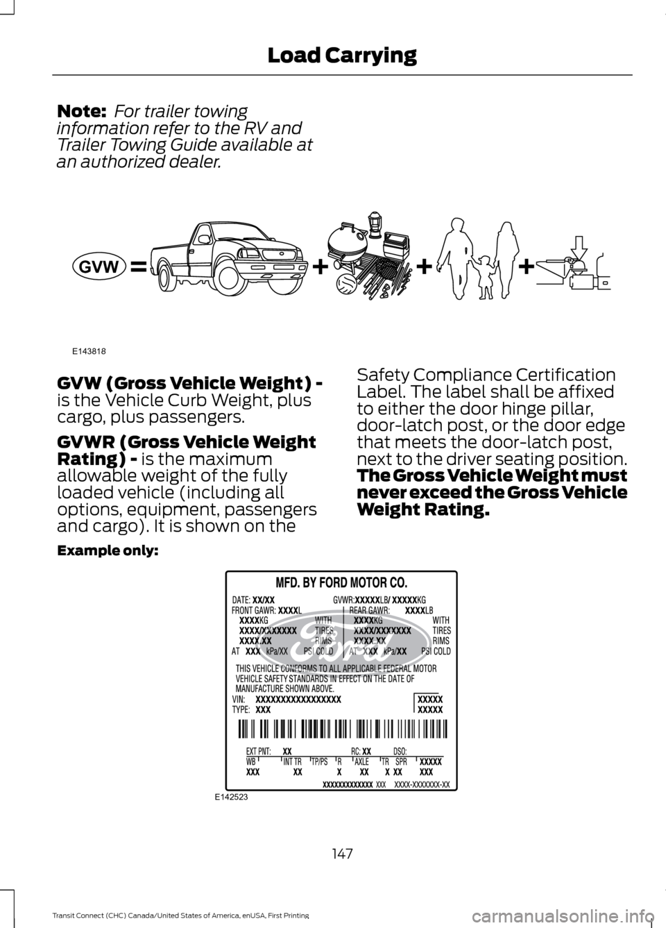
an authorized dealer. GVW (Gross Vehicle Weight) -
is the Vehicle Curb Weight, plus
cargo, plus passengers.
GVWR (Gross Vehicle Weight
Rating) - is the maximum
allowable weight of the fully
loaded vehicle (including all
options, equipment, passengers
and cargo). It is shown on the Safety Compliance Certification
Label. The label shall be affixed
to either the door hinge pillar,
door-latch post, or the door edge
that meets the door-latch post,
next to the driver seating position.
The Gross Vehicle Weight must
never exceed the Gross Vehicle
Weight Rating.
Example only: 147
Transit Connect (CHC) Canada/United States of America, enUSA, First Printing Load CarryingE143818GVW E142523