ABS FORD WINDSTAR 1999 2.G Owners Manual
[x] Cancel search | Manufacturer: FORD, Model Year: 1999, Model line: WINDSTAR, Model: FORD WINDSTAR 1999 2.GPages: 248, PDF Size: 2.28 MB
Page 8 of 248
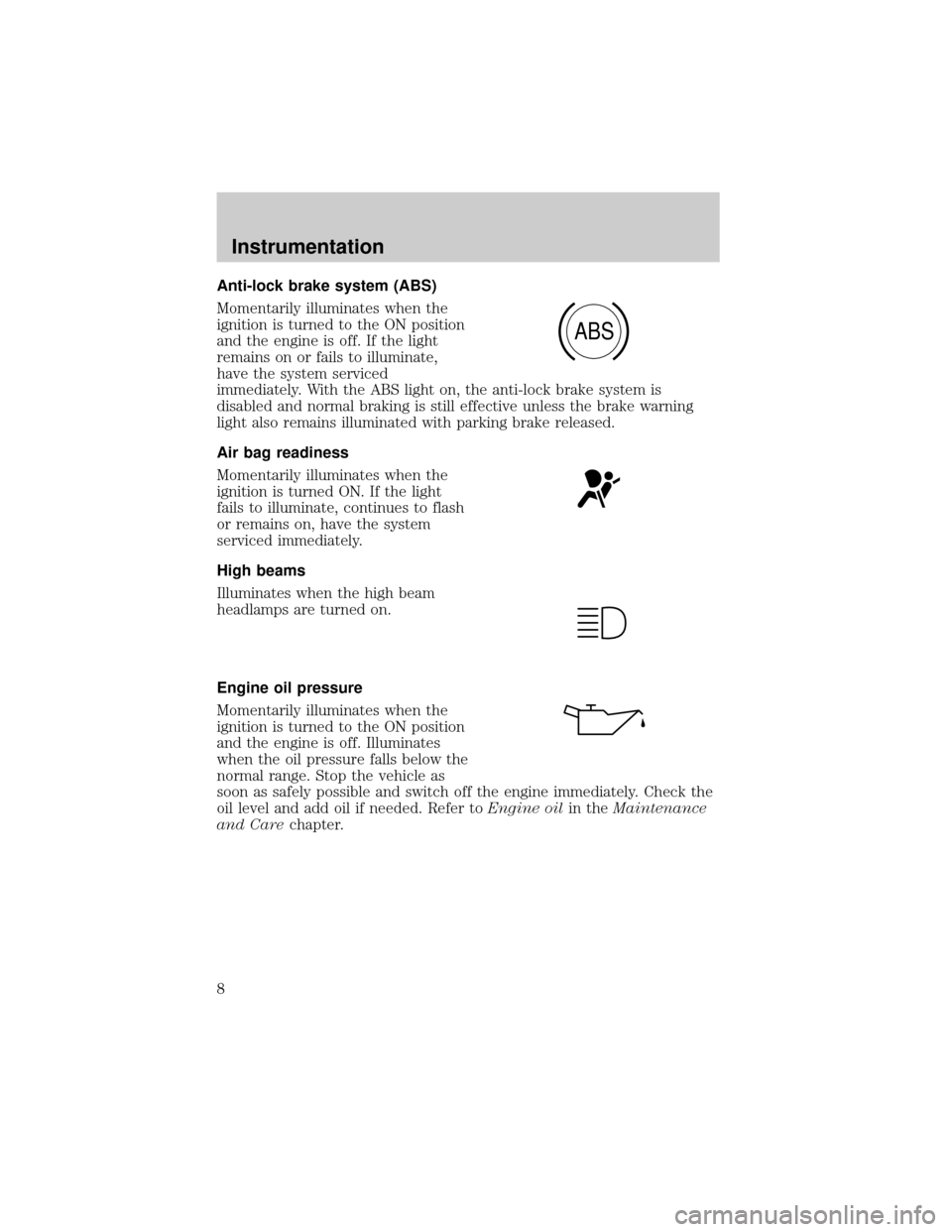
Anti-lock brake system (ABS)
Momentarily illuminates when the
ignition is turned to the ON position
and the engine is off. If the light
remains on or fails to illuminate,
have the system serviced
immediately. With the ABS light on, the anti-lock brake system is
disabled and normal braking is still effective unless the brake warning
light also remains illuminated with parking brake released.
Air bag readiness
Momentarily illuminates when the
ignition is turned ON. If the light
fails to illuminate, continues to flash
or remains on, have the system
serviced immediately.
High beams
Illuminates when the high beam
headlamps are turned on.
Engine oil pressure
Momentarily illuminates when the
ignition is turned to the ON position
and the engine is off. Illuminates
when the oil pressure falls below the
normal range. Stop the vehicle as
soon as safely possible and switch off the engine immediately. Check the
oil level and add oil if needed. Refer toEngine oilin theMaintenance
and Carechapter.
ABS
Instrumentation
8
Page 115 of 248
4. Lift up the back of the seat by the release controls to clear the floor
latches and then pull the seat rearward until the front hooks have come
out of the floor tubs.
5. Remove the seat.
To install the seat:
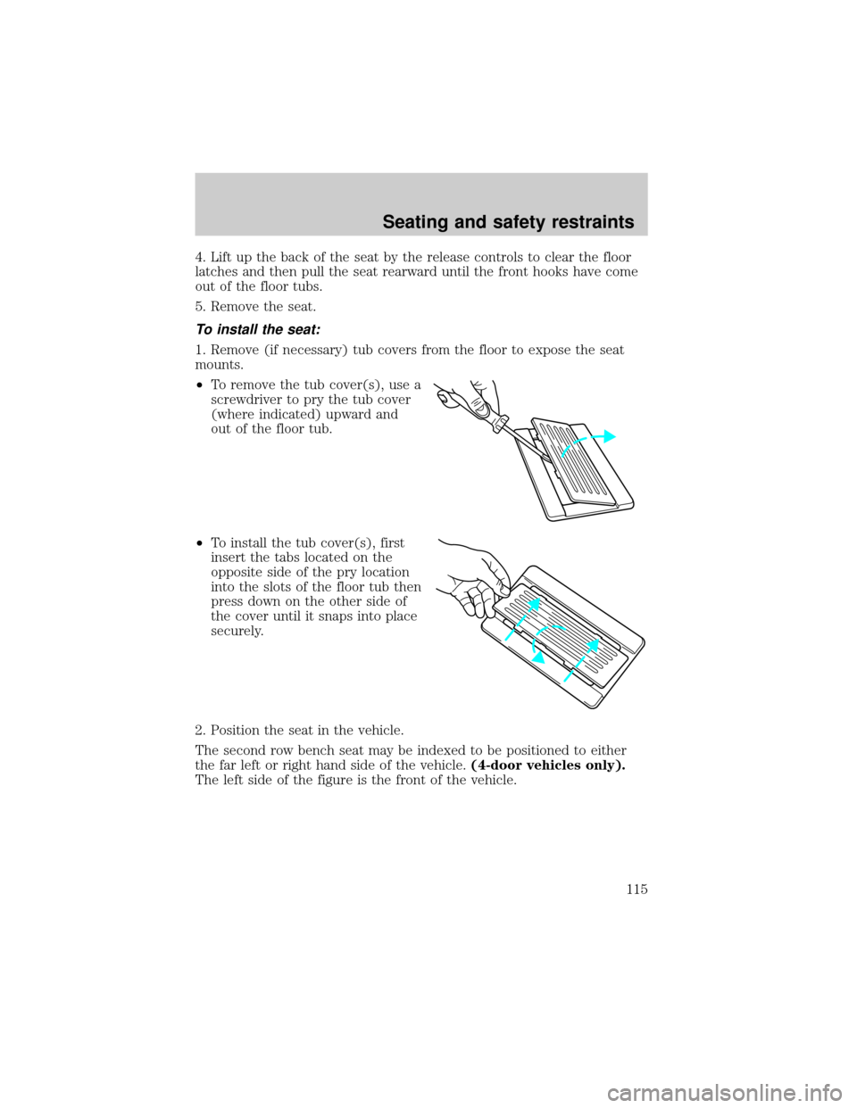
1. Remove (if necessary) tub covers from the floor to expose the seat
mounts.
²To remove the tub cover(s), use a
screwdriver to pry the tub cover
(where indicated) upward and
out of the floor tub.
²To install the tub cover(s), first
insert the tabs located on the
opposite side of the pry location
into the slots of the floor tub then
press down on the other side of
the cover until it snaps into place
securely.
2. Position the seat in the vehicle.
The second row bench seat may be indexed to be positioned to either
the far left or right hand side of the vehicle.(4-door vehicles only).
The left side of the figure is the front of the vehicle.
Seating and safety restraints
115
Page 145 of 248
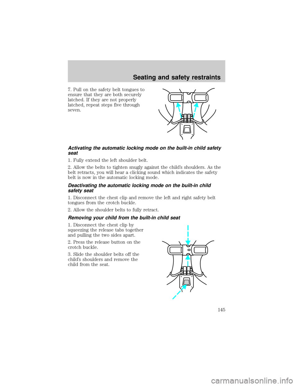
7. Pull on the safety belt tongues to
ensure that they are both securely
latched. If they are not properly
latched, repeat steps five through
seven.
Activating the automatic locking mode on the built-in child safety
seat
1. Fully extend the left shoulder belt.
2. Allow the belts to tighten snugly against the child's shoulders. As the
belt retracts, you will hear a clicking sound which indicates the safety
belt is now in the automatic locking mode.
Deactivating the automatic locking mode on the built-in child
safety seat
1. Disconnect the chest clip and remove the left and right safety belt
tongues from the crotch buckle.
2. Allow the shoulder belts to fully retract.
Removing your child from the built-in child seat
1. Disconnect the chest clip by
squeezing the release tabs together
and pulling the two sides apart.
2. Press the release button on the
crotch buckle.
3. Slide the shoulder belts off the
child's shoulders and remove the
child from the seat.
Seating and safety restraints
145
Page 151 of 248
BRAKES
Your service brakes are self-adjusting. Refer to the scheduled
maintenance guide for scheduled maintenance.
Occasional brake noise is normal and often does not indicate a
performance concern with the vehicle's brake system. In normal
operation, automotive brake systems may emit occasional or intermittent
squeal or groan noises when the brakes are applied. Such noises are
usually heard during the first few brake applications in the morning;
however, they may be heard at any time while braking and can be
aggravated by environmental conditions such as cold, heat, moisture,
road dust, salt or mud. If a ªmetal-to-metal,º ªcontinuous grindingº or
ªcontinuous squealº sound is present while braking, the brake linings
may be worn-out and should be inspected by a qualified service
technician.
Anti-lock brake system (ABS)
On vehicles equipped with an anti-lock braking system (ABS), a noise
from the hydraulic pump motor and pulsation in the pedal may be
observed during ABS braking events. Pedal pulsation coupled with noise
while braking under panic conditions or on loose gravel, bumps, wet or
snowy roads is normal and indicates proper functioning of the vehicle's
anti-lock brake system. The ABS performs a self-check at 17 km/h
(10 mph) after you start the engine and begin to drive away. A brief
mechanical noise may be heard during this test. This is normal. If a
malfunction is found, the ABS warning light will come on. If the vehicle
has continuous vibration or shudder in the steering wheel while braking,
the vehicle should be inspected by a qualified service technician.
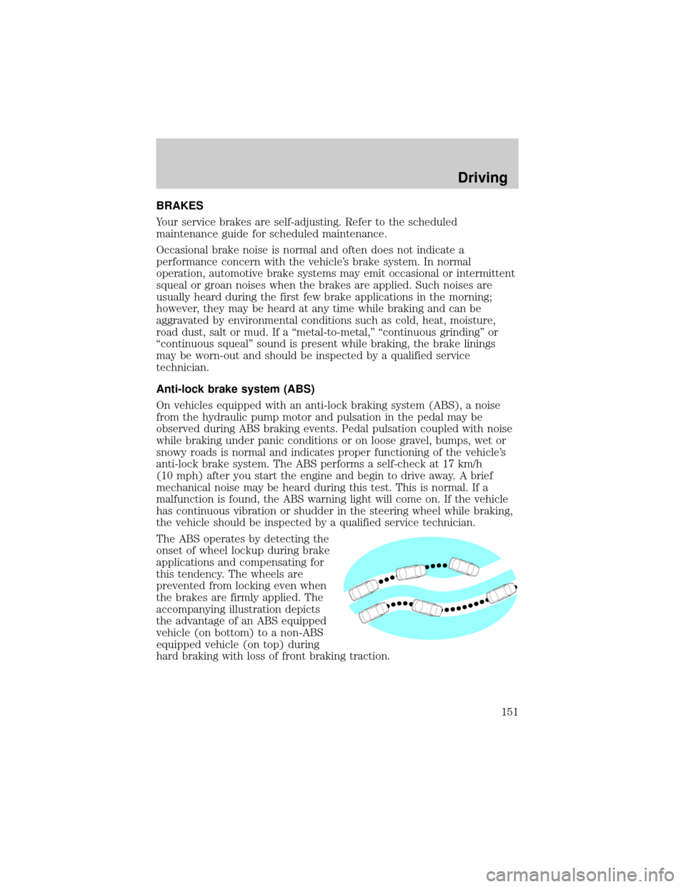
The ABS operates by detecting the
onset of wheel lockup during brake
applications and compensating for
this tendency. The wheels are
prevented from locking even when
the brakes are firmly applied. The
accompanying illustration depicts
the advantage of an ABS equipped
vehicle (on bottom) to a non-ABS
equipped vehicle (on top) during
hard braking with loss of front braking traction.
Driving
151
Page 152 of 248
ABS warning lamp
The
ABSwarning lamp in the instrument cluster momentarily illuminates
when the ignition is turned on and the engine is off. If the light does not
illuminate momentarily at start up or remains on the ABS needs to be
serviced.
With the ABS light on, the anti-lock
brake system is disabled and normal
braking is still effective unless the
brake warning light also remains
illuminated with parking brake
released. (If your brake warning lamp illuminates, have your vehicle
serviced immediately).
Using ABS
²In an emergency or when maximum efficiency from the ABS is
required, apply continuous full force on the brake. The ABS will be
activated immediately, thus allowing you to retain full steering control
of your vehicle and, providing there is sufficient space, will enable you
to avoid obstacles and bring the vehicle to a controlled stop.
²The Anti-Lock system does not decrease the time necessary to apply
the brakes or always reduce stopping distance. Always leave enough
room between your vehicle and the vehicle in front of you to stop.
²We recommend that you familiarize yourself with this braking
technique. However, avoid taking any unnecessary risks.
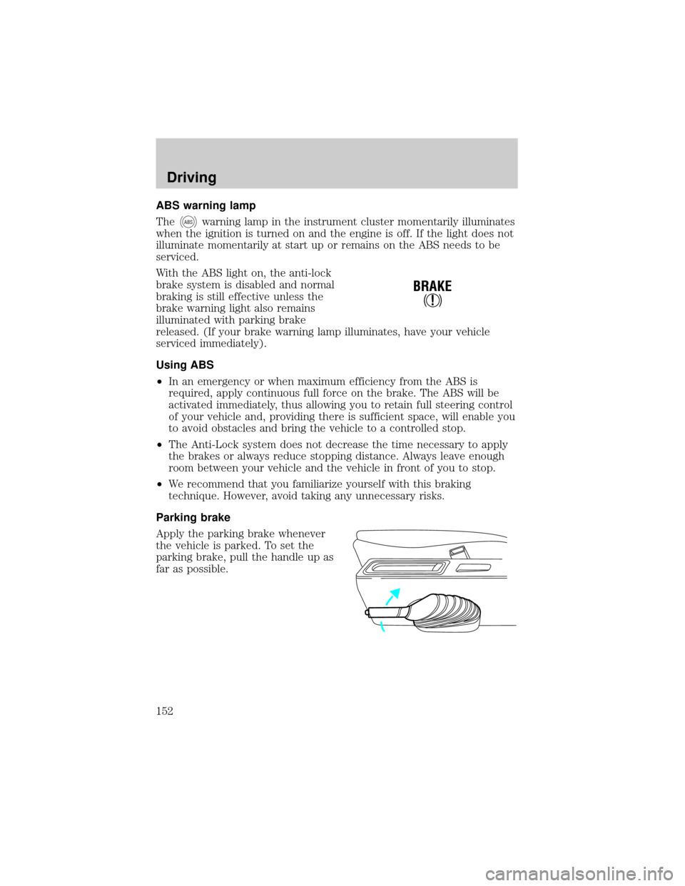
Parking brake
Apply the parking brake whenever
the vehicle is parked. To set the
parking brake, pull the handle up as
far as possible.
!
BRAKE
Driving
152
Page 153 of 248
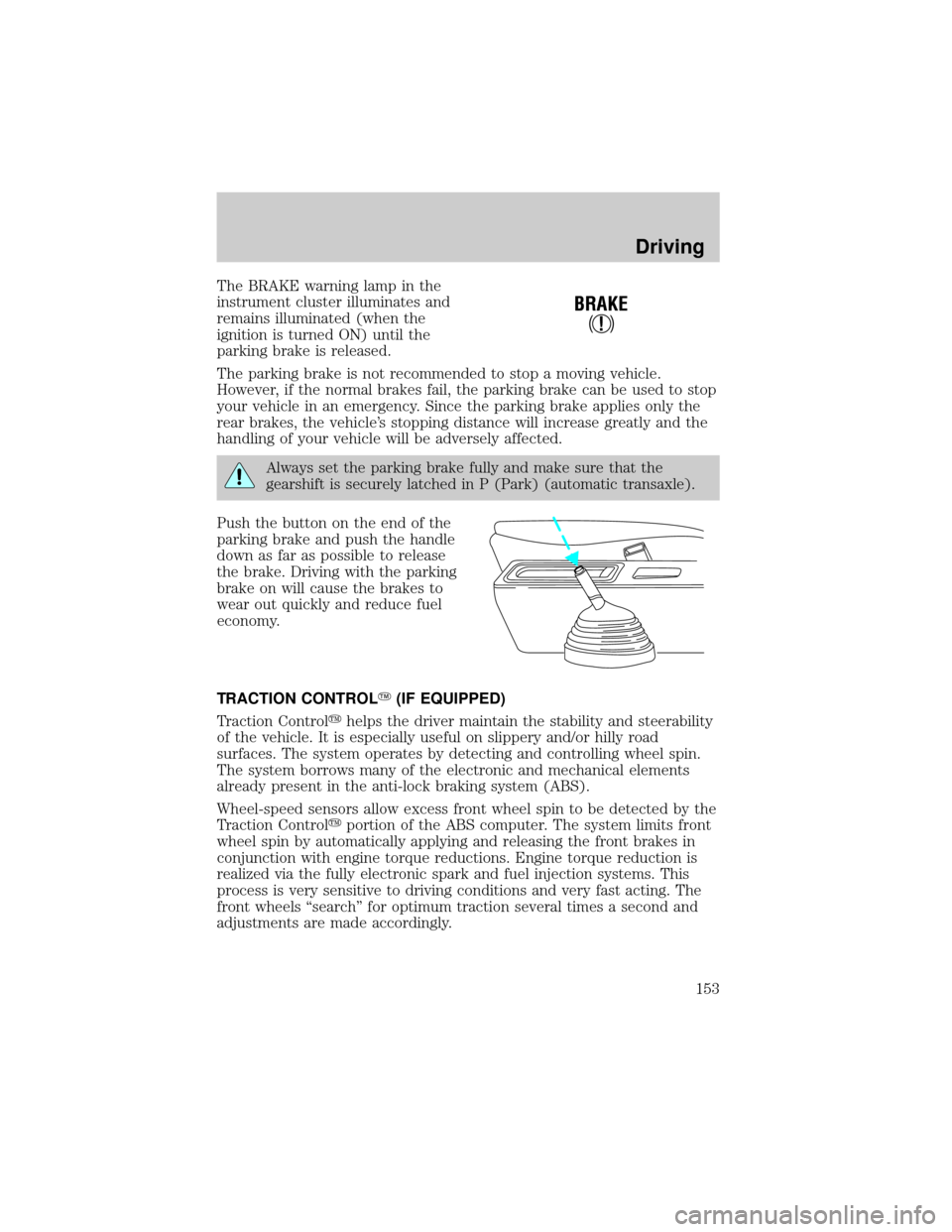
The BRAKE warning lamp in the
instrument cluster illuminates and
remains illuminated (when the
ignition is turned ON) until the
parking brake is released.
The parking brake is not recommended to stop a moving vehicle.
However, if the normal brakes fail, the parking brake can be used to stop
your vehicle in an emergency. Since the parking brake applies only the
rear brakes, the vehicle's stopping distance will increase greatly and the
handling of your vehicle will be adversely affected.
Always set the parking brake fully and make sure that the
gearshift is securely latched in P (Park) (automatic transaxle).
Push the button on the end of the
parking brake and push the handle
down as far as possible to release
the brake. Driving with the parking
brake on will cause the brakes to
wear out quickly and reduce fuel
economy.
TRACTION CONTROLY(IF EQUIPPED)
Traction Controlyhelps the driver maintain the stability and steerability
of the vehicle. It is especially useful on slippery and/or hilly road
surfaces. The system operates by detecting and controlling wheel spin.
The system borrows many of the electronic and mechanical elements
already present in the anti-lock braking system (ABS).
Wheel-speed sensors allow excess front wheel spin to be detected by the
Traction Controlyportion of the ABS computer. The system limits front
wheel spin by automatically applying and releasing the front brakes in
conjunction with engine torque reductions. Engine torque reduction is
realized via the fully electronic spark and fuel injection systems. This
process is very sensitive to driving conditions and very fast acting. The
front wheels ªsearchº for optimum traction several times a second and
adjustments are made accordingly.
!
BRAKE
Driving
153
Page 166 of 248
LUGGAGE RACK (IF EQUIPPED)
Maximum load is 75 kg (165 lbs) on the roof rack structure, or 45 kg
(100 lbs) on the roof panel slats, evenly distributed. If it is not possible
to distribute the load, position it as far rearward as possible. Use
adjustable tie down loops to secure the load.
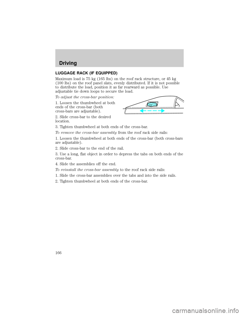
To adjust the cross-bar position:
1. Loosen the thumbwheel at both
ends of the cross-bar (both
cross-bars are adjustable).
2. Slide cross-bar to the desired
location.
3. Tighten thumbwheel at both ends of the cross-bar.
To remove the cross-bar assemblyfrom the roof rack side rails:
1. Loosen the thumbwheel at both ends of the cross-bar (both cross-bars
are adjustable).
2. Slide cross-bar to the end of the rail.
3. Use a long, flat object in order to depress the tabs on both ends of the
cross-bar.
4. Slide the assemblies off the end.
To reinstall the cross-bar assemblyto the roof rack side rails:
1. Slide the cross-bar assemblies over the tabs and into the side rails.
2. Tighten thumbwheel at both ends of the cross-bar.
Driving
166
Page 171 of 248
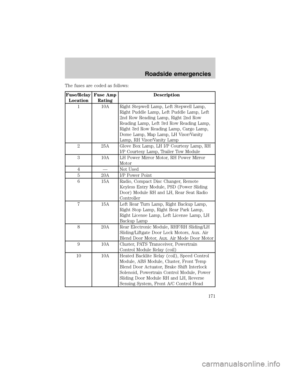
The fuses are coded as follows:
Fuse/Relay
LocationFuse Amp
RatingDescription
1 10A Right Stepwell Lamp, Left Stepwell Lamp,
Right Puddle Lamp, Left Puddle Lamp, Left
2nd Row Reading Lamp, Right 2nd Row
Reading Lamp, Left 3rd Row Reading Lamp,
Right 3rd Row Reading Lamp, Cargo Lamp,
Dome Lamp, Map Lamp, LH Visor/Vanity
Lamp, RH Visor/Vanity Lamp
2 25A Glove Box Lamp, LH I/P Courtesy Lamp, RH
I/P Courtesy Lamp, Trailer Tow Module
3 10A LH Power Mirror Motor, RH Power Mirror
Motor
4 Ð Not Used
5 20A I/P Power Point
6 15A Radio, Compact Disc Changer, Remote
Keyless Entry Module, PSD (Power Sliding
Door) Module RH and LH, Rear Seat Radio
Controller
7 15A Left Rear Turn Lamp, Right Backup Lamp,
Right Stop Lamp, Right Rear Park Lamp,
Right License Lamp, Left License Lamp, LH
Backup Lamp
8 20A Rear Electronic Module, RHF/RH Sliding/LH
Sliding/Liftgate Door Lock Motors, Aux. Air
Blend Door Motor, Aux. Air Mode Door Motor
9 10A Cluster, PATS Transceiver, Powertrain
Control Module Relay (coil)
10 10A Heated Backlite Relay (coil), Speed Control
Module, ABS Module, Cluster, Front Temp
Blend Door Actuator, Brake Shift Interlock
Solenoid, Powertrain Control Module, Power
Sliding Door Module RH and LH, Reverse
Sensing System, Front A/C Control Head
Roadside emergencies
171
Page 175 of 248
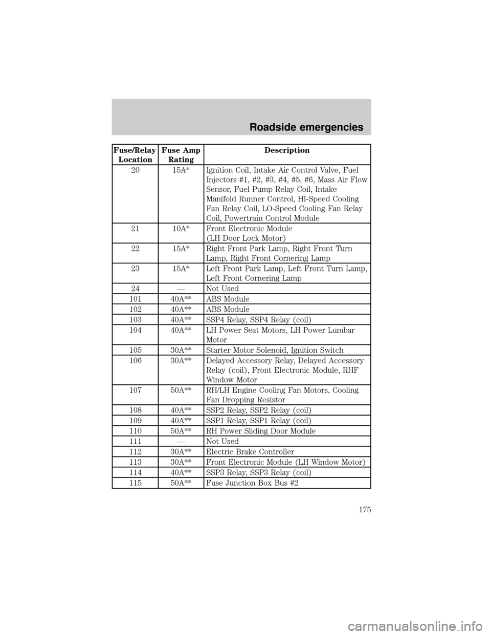
Fuse/Relay
LocationFuse Amp
RatingDescription
20 15A* Ignition Coil, Intake Air Control Valve, Fuel
Injectors #1, #2, #3, #4, #5, #6, Mass Air Flow
Sensor, Fuel Pump Relay Coil, Intake
Manifold Runner Control, HI-Speed Cooling
Fan Relay Coil, LO-Speed Cooling Fan Relay
Coil, Powertrain Control Module
21 10A* Front Electronic Module
(LH Door Lock Motor)
22 15A* Right Front Park Lamp, Right Front Turn
Lamp, Right Front Cornering Lamp
23 15A* Left Front Park Lamp, Left Front Turn Lamp,
Left Front Cornering Lamp
24 Ð Not Used
101 40A** ABS Module
102 40A** ABS Module
103 40A** SSP4 Relay, SSP4 Relay (coil)
104 40A** LH Power Seat Motors, LH Power Lumbar
Motor
105 30A** Starter Motor Solenoid, Ignition Switch
106 30A** Delayed Accessory Relay, Delayed Accessory
Relay (coil), Front Electronic Module, RHF
Window Motor
107 50A** RH/LH Engine Cooling Fan Motors, Cooling
Fan Dropping Resistor
108 40A** SSP2 Relay, SSP2 Relay (coil)
109 40A** SSP1 Relay, SSP1 Relay (coil)
110 50A** RH Power Sliding Door Module
111 Ð Not Used
112 30A** Electric Brake Controller
113 30A** Front Electronic Module (LH Window Motor)
114 40A** SSP3 Relay, SSP3 Relay (coil)
115 50A** Fuse Junction Box Bus #2
Roadside emergencies
175
Page 215 of 248

²Avoid getting fuel liquid in your eyes. If fuel is splashed in the eyes,
remove contact lenses (if worn), flush with water for 15 minutes and
seek medical attention. Failure to seek proper medical attention could
lead to permanent injury.
²Fuels can also be harmful if absorbed through the skin. If fuel is
splashed on the skin and/or clothing, promptly remove contaminated
clothing and wash skin thoroughly with soap and water. Repeated or
prolonged skin contact with fuel liquid or vapor causes skin irritation.
²Be particularly careful if you are taking ªAntabuseº or other forms of
disulfiram for the treatment of alcoholism. Breathing gasoline vapors,
or skin contact could cause an adverse reaction. In sensitive
individuals, serious personal injury or sickness may result. If fuel is
splashed on the skin, promptly wash skin thoroughly with soap and
water. Consult a physician immediately if you experience an adverse
reaction.
Fuel Filler Cap
Your fuel tank filler cap has an indexed design with a one-eighth turn
on/off feature.
When fueling your vehicle:
1. Turn the engine off.
2. Carefully turn the filler cap counterclockwise 1/8 of a turn until it
stops.
3. Pull to remove the cap from the fuel filler pipe.
4. To install the cap, align the tabs on the cap with the notches on the
filler pipe.
5. Turn the filler cap clockwise 1/8 of a turn until it stops.
If the ªService Engine Soon/Check Engineº indicator comes on and stays
on when you start the engine, the fuel filler cap may not be properly
installed. Turn off the engine, remove the fuel filler cap and reinstall it
being careful to align the cap properly.
If you must replace the fuel filler cap, replace it with a genuine
Ford or Motorcraft part. The customer warranty may be void for
any damage to the fuel tank or fuel system if a genuine Ford or
Motorcraft fuel filler cap is not used.
Maintenance and care
215