diagram GEELY CK 2008 User Guide
[x] Cancel search | Manufacturer: GEELY, Model Year: 2008, Model line: CK, Model: GEELY CK 2008Pages: 392, PDF Size: 38.86 MB
Page 235 of 392

2283. Speaker soundless in all modes
Wiring Diagram
(1) Check LCD (Liquid Crystal Display) illumination
1Turn ignition switch to ACC
2Connect radio assembly continuity
3Switch on position lamp
Standard: Radio assembly LCD light goes on
Abnormal:Go to Step (7)
Normal:Go to Next Step
(2) Control volume and adjust volume balance
�yOperate the radio assembly to adjust volume balance and find soundless speaker
Check and replace the radio assembly if all the speakers are soundless
Check and replace the soundless speakers if some of the speakers are soundlessMain Fuse BoxRadio and CDIgnition switchFusible Link BoxBatteryLeft Rear SpeakerRight Rear SpeakerLeft tweeter SpeakerRight tweeter SpeakerLeft Front Speaker
Right Front Speaker
Page 282 of 392

275VIII. ABS ECU Connector Pin LayoutABS ECU Connector (End Views)
Electrical Wiring DiagramCombination MeterABS Warning Light
Drive ModuleABS ECU
ABS RR Wheel Sensor
ABS LR Wheel Sensor ABS RF Wheel Sensor
ABS LF Wheel Sensor
Brake Lamp Switch
Page 308 of 392

301 4. Heater
Figure 5 Heater Door Control Diagram
The heater comprises the heater radiator (heat exchanger), the plastic case forming the air duct, connecting
rods adjusting different air ducts and the door. The two groups of combination doors in the heater case are
connected to the heating control mechanism by the cable. The first group is the two couple action doors
adjusting the air mix ratio that are located in the outlet and inlet each; the second group comprises 4 doors
controlling the air outlet vents, where the upper center one controls the front outlet vent, each of the upper
left and right sides controls a defogger outlet vent and lower foot outlet vent. Figure 5 shows the working
principle of temperature adjustment door. The d) , c) , e) , f) in the figure indicate the outlet air flow direction
as the result of the adjustment of the control knob in the heating control mechanism panel.Hot Wind LocationCold Wind LocationLinkageRadiator CoreRadiator CoreTemperature Adjustment
Door Working PrincipleFoot OutletTo Front OutletTo DefrosterRadiator CoreTo Front OutletRadiator CoreFoot OutletFoot OutletTo Defroster
Page 309 of 392
302Section 3 A/C controlling systemI. Introduction and CompositionIn order to ensure the effective opeation of the A/C system in any operating condition, some advanced
electric control devices are used to protect the A/C system in adverse engine operating condition.
The electrical control part consists of: A/C switch, relay, evaporator temperature sensor, water temperature
sensor, pressure switch, ECU...etc.
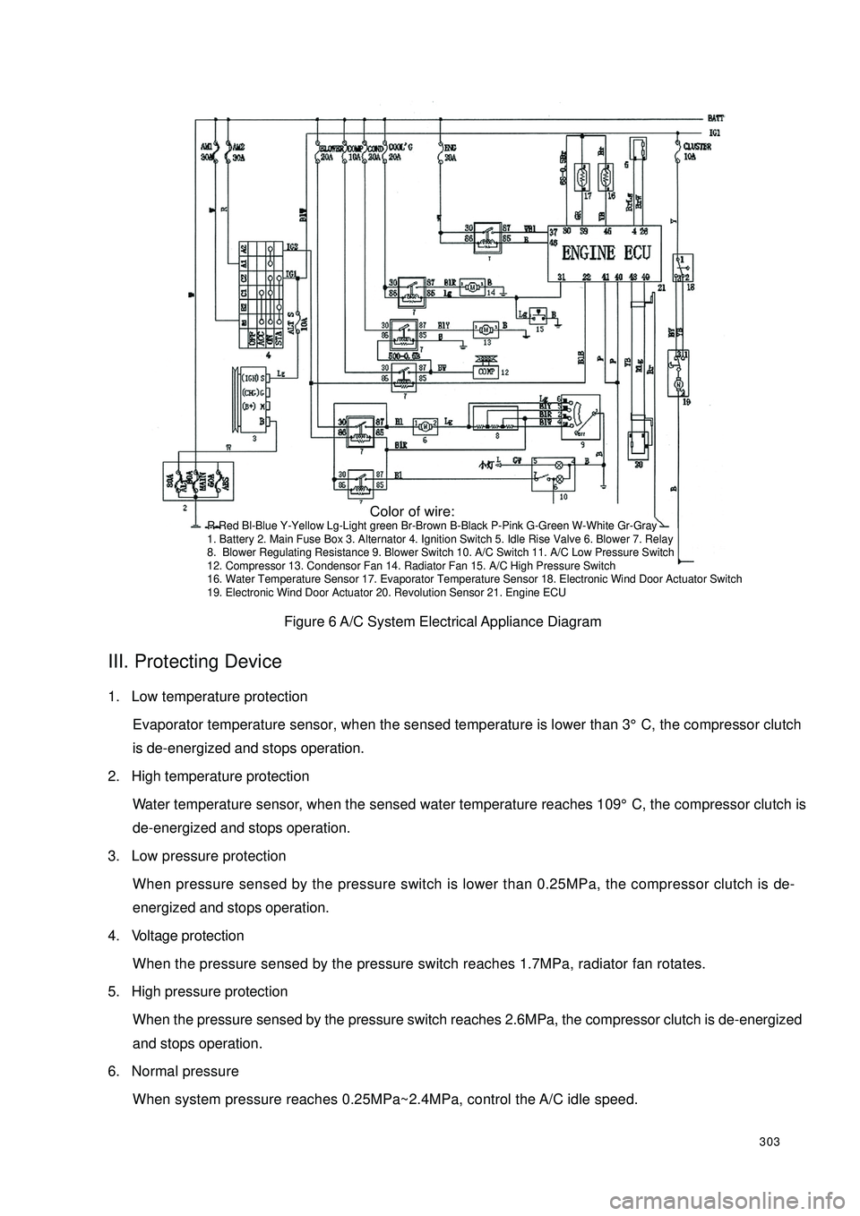
A/C system circuit diagram is shown in Figure 6.II. controlling system feature(1) The condenser fan's power is 90W;
(2) The performance of the condenser fan is controlled by ECU, pressure switch;
(3) Cut off the electrical power of the A/C compressor clutch when the water temperature reaches 109°C;
(4) Connect blower switch 9 to rotate the blower motor 6 to ensure A/C normal operation. Connect A/C
switch 10 to output A/C request signal to ECU.
(5) After ECU receives the request signal and the one from the evaporator temperature sensor 17, if the
engine is at idle, ECU first increases the engine speed to 950 ± 50r/min, lest the A/C operation enhance
the load and lower the engine speed or result in engine off. And then the ECU can respond. If the engine
is in accelerating condition, ECU does not respond immediately either, and respond 5 seconds later after
the end of the accelerating condition. ECU send out a A/C control signal from pin 22 to relay 7, command
the relay to suction in. With the low pressure switch 11 closed, the compressor 12 starts to work when the
magnetic clutch suction on. The condenser relay holds in and condenser blower 13 rotates. When high
pressure switch 15 is closed, have the relay 7 hold in and the water tank fan 14 rotates. When the water
temperature sensor 16's temperature is higher than 109°C, ECU shut off the output signal of the pin 22
and A/C stops operation.
(6) When the Refrigeration system pressure is over 1.7MPa, radiator fan will rotato. Disconnect A/C
compressor Refrigeration system power supply when the pressure is over 2.6MPa or less than 0.25MPa;
Page 310 of 392
303Figure 6 A/C System Electrical Appliance DiagramIII. Protecting Device1. Low temperature protection
Evaporator temperature sensor, when the sensed temperature is lower than 3°C, the compressor clutch
is de-energized and stops operation.
2. High temperature protection
Water temperature sensor, when the sensed water temperature reaches 109°C, the compressor clutch is
de-energized and stops operation.
3. Low pressure protection
When pressure sensed by the pressure switch is lower than 0.25MPa, the compressor clutch is de-
energized and stops operation.
4. Voltage protection
When the pressure sensed by the pressure switch reaches 1.7MPa, radiator fan rotates.
5. High pressure protection
When the pressure sensed by the pressure switch reaches 2.6MPa, the compressor clutch is de-energized
and stops operation.
6. Normal pressure
When system pressure reaches 0.25MPa~2.4MPa, control the A/C idle speed. Color of wire:R-Red Bl-Blue Y-Yellow Lg-Light green Br-Brown B-Black P-Pink G-Green W-White Gr-Gray
1. Battery 2. Main Fuse Box 3. Alternator 4. Ignition Switch 5. Idle Rise Valve 6. Blower 7. Relay
8. Blower Regulating Resistance 9. Blower Switch 10. A/C Switch 11. A/C Low Pressure Switch
12. Compressor 13. Condensor Fan 14. Radiator Fan 15. A/C High Pressure Switch
16. Water Temperature Sensor 17. Evaporator Temperature Sensor 18. Electronic Wind Door Actuator Switch
19. Electronic Wind Door Actuator 20. Revolution Sensor 21. Engine ECU
Page 336 of 392
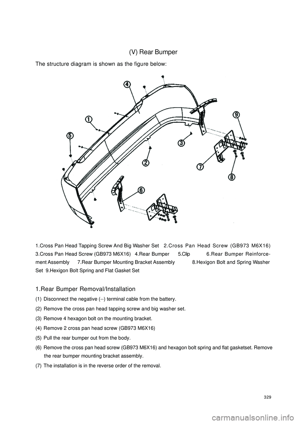
329(V) Rear BumperThe structure diagram is shown as the figure below:
1.Cross Pan Head Tapping Screw And Big Washer Set2.Cross Pan Head Screw (GB973 M6X16)
3.Cross Pan Head Screw (GB973 M6X16) 4.Rear Bumper5.Clip6.Rear Bumper Reinforce-
ment Assembly 7.Rear Bumper Mounting Bracket Assembly8.Hexigon Bolt and Spring Washer
Set 9.Hexigon Bolt Spring and Flat Gasket Set
1.Rear Bumper Removal/Installation
(1) Disconnect the negative (--) terminal cable from the battery.
(2) Remove the cross pan head tapping screw and big washer set.
(3) Remove 4 hexagon bolt on the mounting bracket.
(4) Remove 2 cross pan head screw (GB973 M6X16)
(5) Pull the rear bumper out from the body.
(6) Remove the cross pan head screw (GB973 M6X16) and hexagon bolt spring and flat gasketset. Remove
the rear bumper mounting bracket assembly.
(7) The installation is in the reverse order of the removal.
Page 350 of 392

343(IX) A pillar inside trim and front door sillA pillar inside trim and front door sill diagram
A pillar inside trim and front door sill diagram
1. Right A Pillar Inside Trim 2. Left A Pillar Inside Trim 3. Right Front Door Sill
4. Left Front Door Sill5.D-Clip 6. Steel Clip7. Cross Slot Head Self-tapping Screw
1. Removal
1Remove the installed right front door sill, left front door sill self-tapping screw cross screwdriver;
2Use an opener to remove the right A pillar inside trim, A pillar inside trim, right front door sill, left frontdoor sill.
2. Installation
1 Install the right A pillar inside trim, A pillar inside trim, right front door sill , left front door sill to the
corresponding position with clip and steel clip;
2Fix the right front door sill , left front door sill with a tapping screw. 1 2
3
6
4 57
Page 351 of 392

344(X) B pillar inside trimB pillar inside trim diagram:
B Pillar Inside Trim Diagram
1. Right B Pillar Upper Inside Trim 2. Left B Pillar Upper Inside Trim 3. Right Deflector
4. Left Deflector5. Right B Pillar Lower Inside Trim 6. Left B Pillar Lower Inside Trim
7. Right B Pillar Lower Inside Trim Sound Insulator 8. Left B Pillar Lower Inside Trim Sound Insulator
9. Cross Pan Head Tapping Screw10. Steel Clip
1.Removal
1Remove the installed left B pillar lower inside trim, right B pillar lower inside trim tapping screw with a
cross screwdriver;
2Remove the left B pillar lower inside trim, right B pillar lower inside trim with a opener ;
3Remove the seat belt swing ring;
4Remove the right B pillar upper inside trim, leftB pillar upper inside trim tapping screw with the cross
screwdriver;
5Remove the right B pillar upper inside trim, leftB pillar upper inside trim with a opener.
2.Installation
1Clip B pillar inside trim to the corresponding position with clip and steel clip in order;
2Fix the upper inside trim and lower inside trim to the vehicle body with a tapping screw.
2
453
1
6
10
8 79
Page 352 of 392
345(XI) Cpillar inside trim and rear door sillC pillar inside trim and rear door sill diagram:
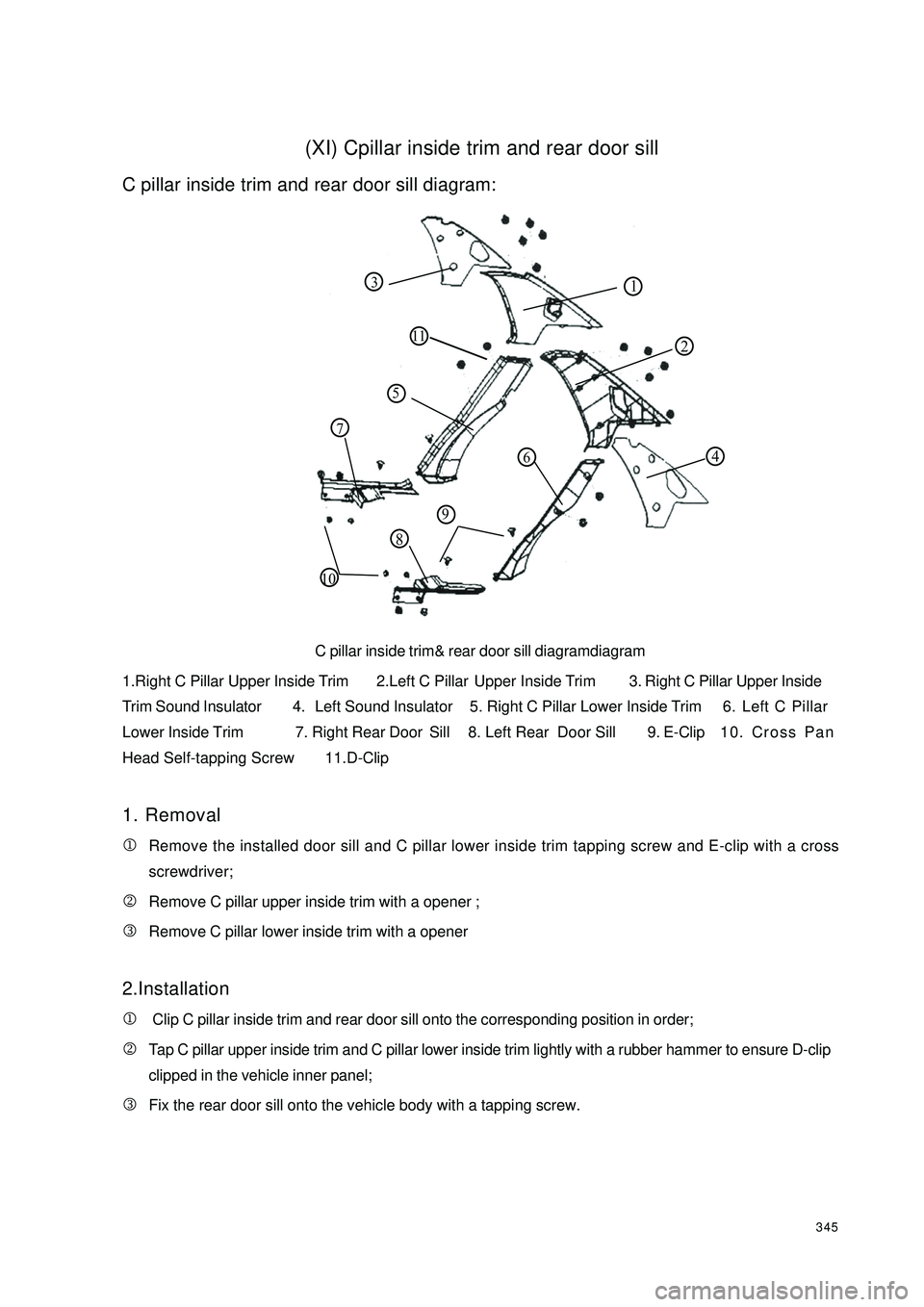
C pillar inside trim& rear door sill diagramdiagram
1.Right C Pillar Upper Inside Trim 2.Left C Pillar Upper Inside Trim 3. Right C Pillar Upper Inside
Trim Sound Insulator 4. Left Sound Insulator 5. Right C Pillar Lower Inside Trim 6. Left C Pillar
Lower Inside Trim 7. Right Rear Door Sill 8. Left Rear Door Sill9. E-Clip10. Cross Pan
Head Self-tapping Screw 11. D-Clip
1. Removal
1Remove the installed door sill and C pillar lower inside trim tapping screw and E-clip with a cross
screwdriver;
2Remove C pillar upper inside trim with a opener ;
3Remove C pillar lower inside trim with a opener
2.Installation
1 Clip C pillar inside trim and rear door sill onto the corresponding position in order;
2Tap C pillar upper inside trim and C pillar lower inside trim lightly with a rubber hammer to ensure D-clip
clipped in the vehicle inner panel;
3Fix the rear door sill onto the vehicle body with a tapping screw.112 110843
57
96
Page 353 of 392
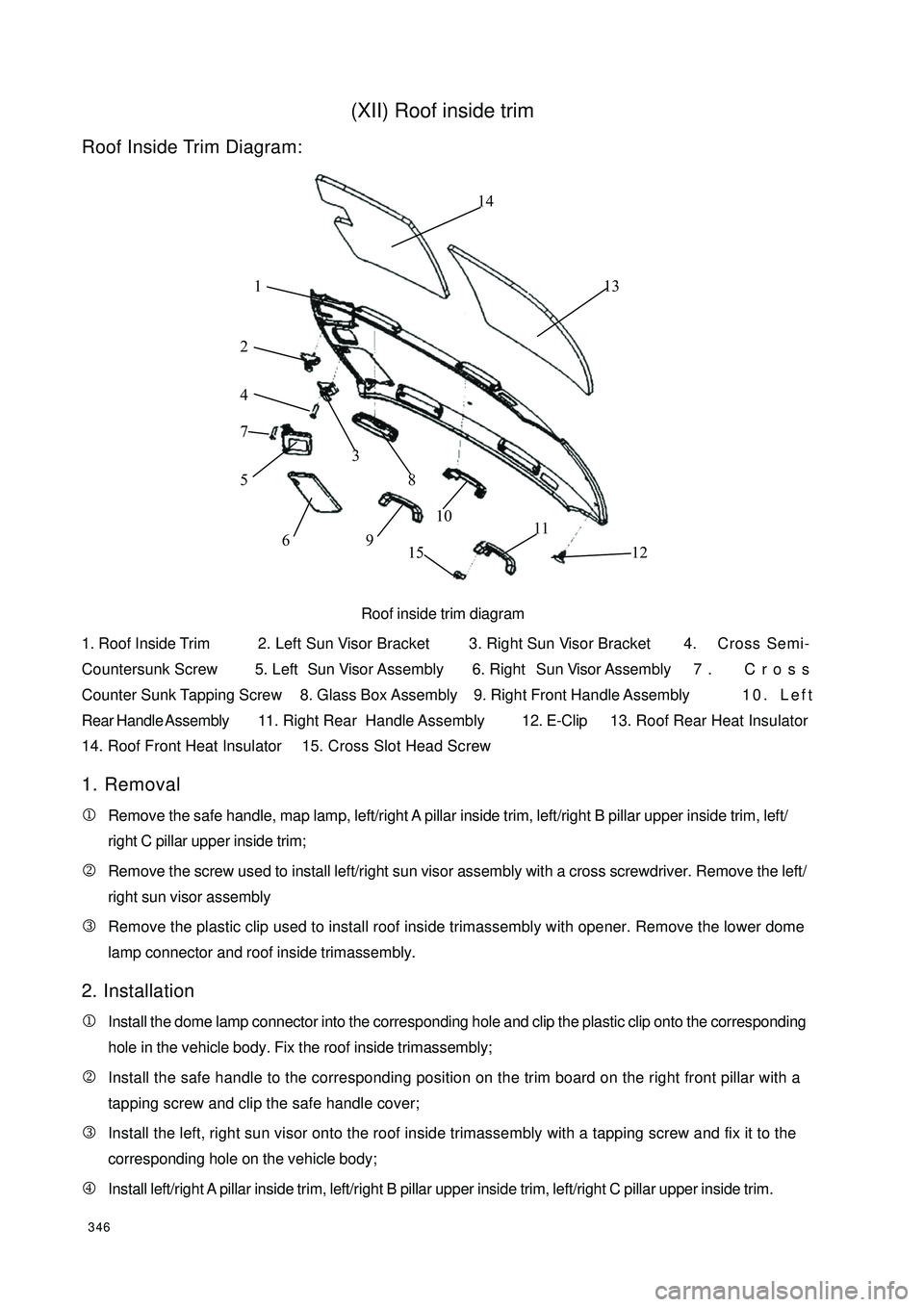
346(XII) Roof inside trimRoof Inside Trim Diagram:
Roof inside trim diagram
1. Roof Inside Trim2. Left Sun Visor Bracket 3. Right Sun Visor Bracket 4. Cross Semi-
Countersunk Screw 5. Left Sun Visor Assembly 6. Right Sun Visor Assembly 7 . Cross
Counter Sunk Tapping Screw 8. Glass Box Assembly 9. Right Front Handle Assembly10. Left
Rear Handle Assembly11. Right Rear Handle Assembly12. E-Clip13. Roof Rear Heat Insulator
14. Roof Front Heat Insulator15. Cross Slot Head Screw
1. Removal
1Remove the safe handle, map lamp, left/right A pillar inside trim, left/right B pillar upper inside trim, left/
right C pillar upper inside trim;
2Remove the screw used to install left/right sun visor assembly with a cross screwdriver. Remove the left/
right sun visor assembly
3Remove the plastic clip used to install roof inside trimassembly with opener. Remove the lower dome
lamp connector and roof inside trimassembly.
2. Installation
1Install the dome lamp connector into the corresponding hole and clip the plastic clip onto the corresponding
hole in the vehicle body. Fix the roof inside trimassembly;
2Install the safe handle to the corresponding position on the trim board on the right front pillar with a
tapping screw and clip the safe handle cover;
3Install the left, right sun visor onto the roof inside trimassembly with a tapping screw and fix it to the
corresponding hole on the vehicle body;
4Install left/right A pillar inside trim, left/right B pillar upper inside trim, left/right C pillar upper inside trim. 2 13 4
5
6 7
8
9 10
11
12 13 1415