diagram GEELY CK 2008 Workshop Manual
[x] Cancel search | Manufacturer: GEELY, Model Year: 2008, Model line: CK, Model: GEELY CK 2008Pages: 392, PDF Size: 38.86 MB
Page 5 of 392

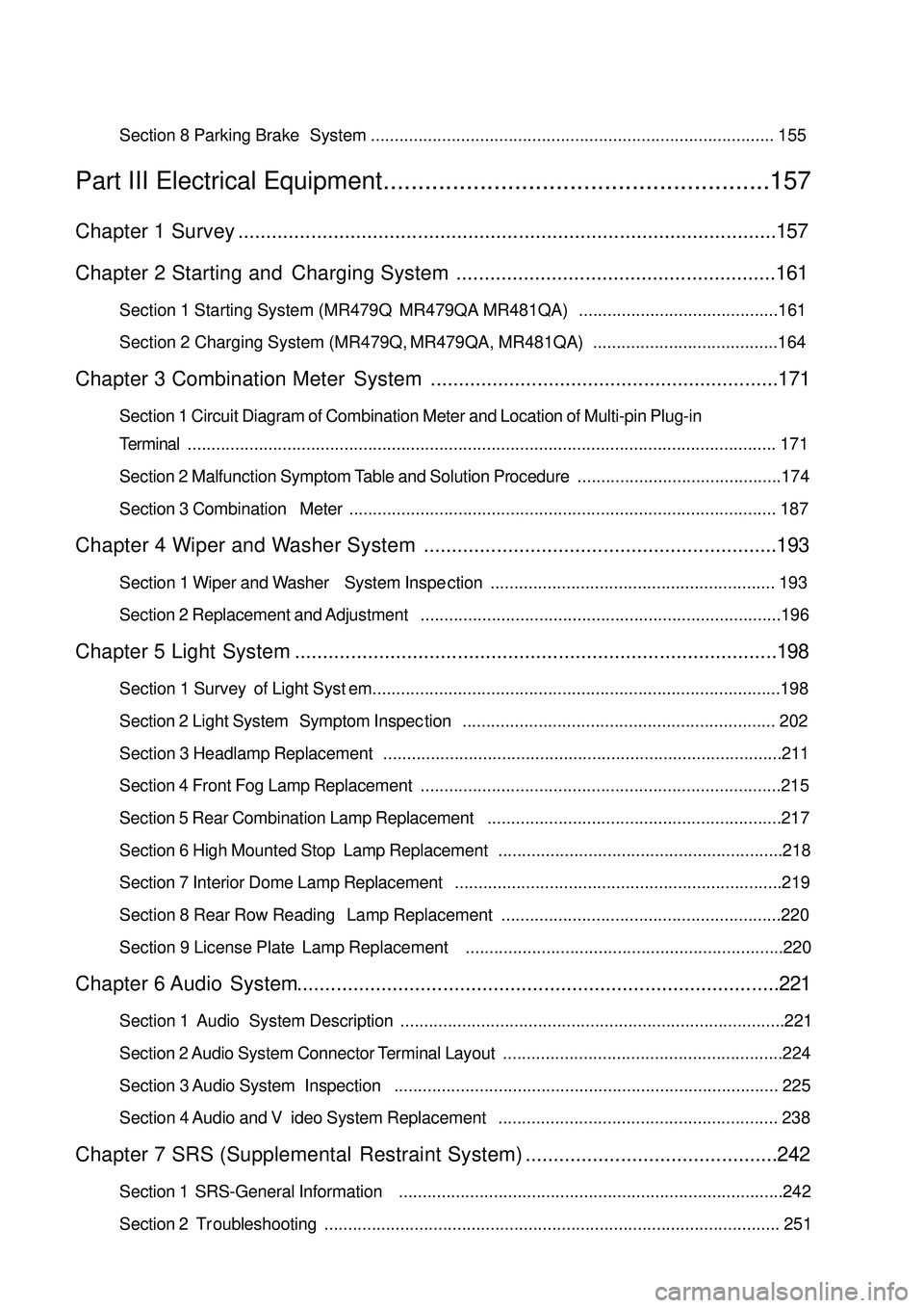
Section 8 Parking Brake System..................................................................................... 155........................................................157Chapter 1 Survey................................................................................................157
Chapter 2 Starting and Charging System.........................................................161Section 1 Starting System (MR479Q MR479QA MR481QA)..........................................161
Section 2 Charging System (MR479Q, MR479QA, MR481QA).......................................164Chapter 3 Combination Meter System..............................................................171Section 1 Circuit Diagram of Combination Meter and Location of Multi-pin Plug-in
Terminal............................................................................................................................ 171
Section 2 Malfunction Symptom Table and Solution Procedure...........................................174
Section 3 Combination Meter.......................................................................................... 187Chapter 4 Wiper and Washer System...............................................................193Section 1 Wiper and Washer System Inspection............................................................ 193
Section 2 Replacement and Adjustment............................................................................196Chapter 5 Light System......................................................................................198Section 1 Survey of Light System......................................................................................198
Section 2 Light System Symptom Inspection.................................................................. 202
Section 3 Headlamp Replacement....................................................................................211
Section 4 Front Fog Lamp Replacement............................................................................215
Section 5 Rear Combination Lamp Replacement..............................................................217
Section 6 High Mounted Stop Lamp Replacement............................................................218
Section 7 Interior Dome Lamp Replacement.....................................................................219
Section 8 Rear Row Reading Lamp Replacement...........................................................220
Section 9 License Plate Lamp Replacement...................................................................220Chapter 6 Audio System......................................................................................221Section 1 Audio System Description.................................................................................221
Section 2 Audio System Connector Terminal Layout...........................................................224
Section 3 Audio System Inspection................................................................................. 225
Section 4 Audio and Video System Replacement........................................................... 238Chapter 7 SRS (Supplemental Restraint System).............................................242Section 1 SRS-General Information.................................................................................242
Section 2 Troubleshooting................................................................................................ 251Part III Electrical Equipment
Page 178 of 392

171Chapter 3 Combination Meter SystemSection 1 Circuit Diagram of Combination Meter and Location of
Multi-pin Plug-in TerminalI. CIRCUIT DIAGRAM OF CONBINATION METERSpeed Signal
Ground The Sensor
Revolution SignalWater Temperature SignaFuel Level GaugeTachometer
SpeedometerWater
Temperature Gauge
Feul Level Gauge
OdometerHigh Beam Lamp
Rear Defrost Lamp
Rear Defog Lamp
Backlight
Water Temperature WarningPower Steering
Fuel WarningCharge
Brake Fluid
Oil Pressure
Engine Malfunction
Driver's seat belt
Park Brake
SRS(main)
SRS(sub)
Page 184 of 392

1772. SPEEDOMETER MALFUNCTION
CIRCUIT DIAGRAM
INSPECTION
(a) Inspect the combination meter assembly
1Remove the combination meter assembly and retain the connection of connectors.
2Inspect continuity
�yInspect continuity between terminals
Standard:
3Inspect voltage between terminals
Standard:
Result and solution:
If it is abnormal, go to (b) Inspect the combination meter assembly speed input signal
If normal, go to (c) Inspect the combination meter assemblyTe ste r c onne c tion Condition Sta ndard c ondition
A9 - ground Norma l c ondition ContinuitySpeedometer SensorCombined Meter AssemblyGround the
Speedometer Sensor
Speedometer Sensor+8V
Power Source
Speed SignalTe ste r c onne c tion Condition Sta nda rd c ondition
A10 - ground Turn the ignition switch to ON 7.5 – 9V
Page 188 of 392

1813. TACHOMETER MALFUNCTION
CIRCUIT DIAGRAM
Inspection procedure
(a) Inspect the combination meter assembly revolution input signal
1Remove the combination meter assembly and retain the connection of connectors.
2Connect the oscilloscope to the terminal B11 and
ground.
3Start the engine
4Inspect the signal wave form
Standard:
Show the correct wave form
Result and solution:
NormalInspect and replace the combination
meter assembly
AbnormalInspect the engine ECU revolution out-
put signalEngine ECUCombined Meter Assembly
Engine Revolution Signal
Page 190 of 392

1834. WATER TEMPERATURE GAUGE MALFUNCTION
CIRCUIT DIAGRAM
(a) Get the value of water temperature with the diagnosis tester
1Connect the diagnosis tester to the diagnosis interface
2Turn the ignition switch to ON
3Read the value of engine water temperature displayed on the diagnosis tester
Standard: The same with the actual engine coolant temperature.
Result and solution:
If it is normal, the water temperature gauge has no malfunction
If abnormal, Inspect the combination meter assembly
(b) Inspect the combination meter assembly
1Inspect resistance
�yRemove the combination meter assembly and disconnect connectors
�yInspect continuity between terminalsWater Temperature SensorCombined Meter Assembly
Water
Temperature
Signal
Page 192 of 392

1855. FUEL GAUGE MALFUNCTION
CIRCUIT DIAGRAM
(a) Inspect the combination meter assembly
1Inspect resistance
�yRemove the combination meter assembly and disconnect connectors
�yInspect continuity between terminals
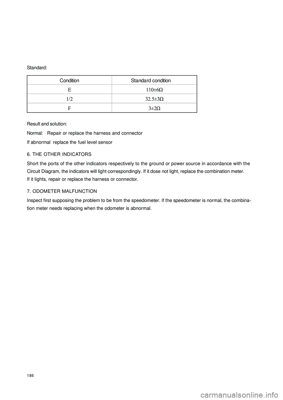
Standard:
Result and solution:
NormalReplace the combination meter assembly
If abnormal inspect the fuel level sensor
2Inspect the fuel level sensor
�yRemove the fuel level sensor
�yAdjust the height of the fuel level sensor and measure its resistance.Te ster connec tionC ondit ionSta ndard c onditionE110±6Ω
1/2 32.5±3Ω
F3±2Ω A12 - groundFuel Level SensorCombined Meter Assembly
Fuel Signal
Page 193 of 392

186Standard:
Result and solution:
Normal:Repair or replace the harness and connector
If abnormal replace the fuel level sensor
6. THE OTHER INDICATORS
Short the ports of the other indicators respectively to the ground or power source in accordance with the
Circuit Diagram, the indicators will light correspondingly. If it dose not light, replace the combination meter.
If it lights, repair or replace the harness or connector.
7. ODOMETER MALFUNCTION
Inspect first supposing the problem to be from the speedometer. If the speedometer is normal, the combina-
tion meter needs replacing when the odometer is abnormal.Condition Standa rd condition
E 110±6Ω
1/2 32.5±3Ω
F3±2Ω
Page 214 of 392

207(a) Inspect light control switch continuity
Inspect each terminal for continuity when the switch is on every position according to the table.
If it is not as specified, replace the switch.
(b) Inspect headlamp dimmer switch continuity
Inspect each terminal for continuity when the switch is on every position according to the table.
If it is not as specified, replace the switch.
(c) Inspect turn signal switch continuity
Inspect each terminal for continuity when the switch is on every position according to the table.
If it is not as specified, replace the switch.S w it c h pos it ion T e s t e d t e r mina l C ondit ion
O FF 5BB2-5BB3 No c ontinuity
TAIL 5BB2-5BB3 ContinuitySwitch position Tested terminal Condition
LO 5BB1-9NB5 Continuity
HI 9NB2-9NB3 Continuity
PASSING 9NA1-9NB3 Continuity5B
5BB1
5BB2
5BB35BA1
5BA39N
9NB1
9NB2
9NB3
9NB4
9NB59NA1
9NA2
9NA3
9NA4Headlamp combinated terminal position diagramSwitch position Tested terminal Condition
Left turn 9NA4-9NA5 Continuity
Straight run 9NA4-9NA5-9NA2 No c ontinuity
Right turn 9NA5-9NA2 Continuity
Page 233 of 392

226II. Inspection1. Power switch system doesn't work
Wiring Diagram
(1) Check radio assembly (+B, ¬ACC, ¬GND)
1Check the continuity between terminals under each operating condition as shown in the table below
Standard:
2Check the voltage between terminals under each operating condition as shown in the table
Standard:
Normal:Repair or replace wire harness, connector
Abnormal:Check or replace radio assemblyMain Fuse BoxRadio and CD
BatteryFusible Link BoxIgnition SwitchTester connection Condition Standard Status
GND Consta nt Status ContinuityTeste r Connec tion Condition Sta nda rd Sta tus
+B - GND Consta nt Status 10~
14V
ACC - GND Ignition switch ACC or ON 10~
14V
Page 234 of 392

2272. The radio backlight does not light up with the illumination switch ON
Wiring Diagram
(1) Check radio assembly (TAIL)
Check the voltage between terminals under each operating condition as shown in the table below.
Standard:
Abnormal:Repair or replace wire harness and connector
Normal:Check and replace radio assemblyMain Fuse BoxRadio and CDFusible Link Box
BatteryLight
Control
Switch
BatteryTeste r Connec tion Condition Sta nda rd Sta tus
TAIL - GND Combined Switch (Light switc h) 10~
14V