lock GEELY CK 2008 User Guide
[x] Cancel search | Manufacturer: GEELY, Model Year: 2008, Model line: CK, Model: GEELY CK 2008Pages: 392, PDF Size: 38.86 MB
Page 82 of 392
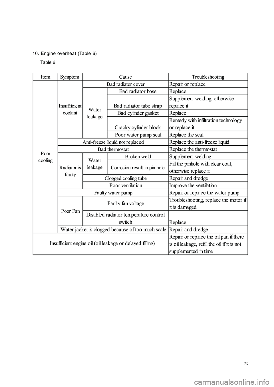
7510. Engine overheat (Table 6)
Table 6Ite m Symptom Trouble shootingRepair or replace
Bad radiator hose Replace
Bad radiator tube strapSupplement welding, otherwise
replace it
Bad cylinder gasket Replace
Cracky cylinder blockRemedy with infiltration technology
or replace it
Poor water pump seal Replace the seal
Replace the anti-freeze liquid
Replace the thermostatBroken we ldSupplement weldingCorrosion result in pin holeFill the pinhole with clear coat,
otherwise replace it
Repair and dredge
Improve the ventilation
Repair or replace the water pump
Troubleshooting, replace the motor if
it is d a ma ge d
Replace
Repair and dredge
Repair or replace the oil pan if there
is o il le a k a ge , r e fill t he o il if it is no t
s up p le me nt e d in t imeCause
Ba d ra diator c over
Clogge d cooling tubePoor ventilationWater
le a ka ge
Anti-fre eze liquid not repla ce d
Bad thermostat
Radiator is
faultyWater
le a ka ge Insufficient
coolantF a ulty fa n vo lta ge
Disabled radiator temperature control
switch
Water jacket is clogged because of too much scale
I ns uffic ie nt e ngine o il ( o il le a k a ge o r d e la ye d filling)P oor
c ooling
Poor FanFaulty water pump
Page 90 of 392
83ECU microcomputer consists of microprocessor, memory, clock generator, timer, I/O interface and input
level A/D converter that are integrated in a large scale integrated circuit chip, that is SCM (Single Chip
Microcomputer).
1. Input level
The input signals from the sensor are pre-processed by the input level. The input signals are sent to protected
circuit first, sometimes through the signal converter and amplifier, and then sent to microcomputer.
The sensor signal is separated into switch type and analog type. Ignition on/off signal, camshaft position
signal, vehicle speed signal and A/C signal are switch type; Signals such as battery voltage, engine temperature,
intake temperature, airflow, intake manifold absolute pressure, throttle opening, excessive air coefficient,
knock, A/C refrigerant pressure are analog type. Analogy signal can only be processed by the digital micro-
computer after being converted into digital signal by A/D converter. Hence, data collection shall be made
first for analog signal, and the sampling shall be maintained also.
Speed and crankshaft position reference signal from the sensor is processed in a dedicated circuit to restrain
the interference pulse.
2. Microcomputer
The microcomputer of the engine electronic control unit is integrated in a single chip microcomputer, consist-
ing of the following:
(1) Microprocessor, microprocessor is also called as central processing unit (CPU), consisting of the following
three parts:
Arithmetic logic unit.
Register group.
Controller.
(2) System assembly, The data transferred among the internal sections of the single chip microcomputer
(SCM) is performed on the internal bus, while that between the SCM and other components is performed
on the external bus. The external bus is also called system bus. It is separated into data bus, address bus
and control bus.
(3) Memory, the memory is designed to store the binary data. The primary components of the memory are:
Memory.
Data register.
Address register, address decoder.
a. Memory controller
(4) A/D converter
(5) I/O interface.
(6) Clock generator.
(7) Timer
(8) CAPCOM unit.
(9) Watchdog timer.
(10) Interrupt system.
Page 93 of 392
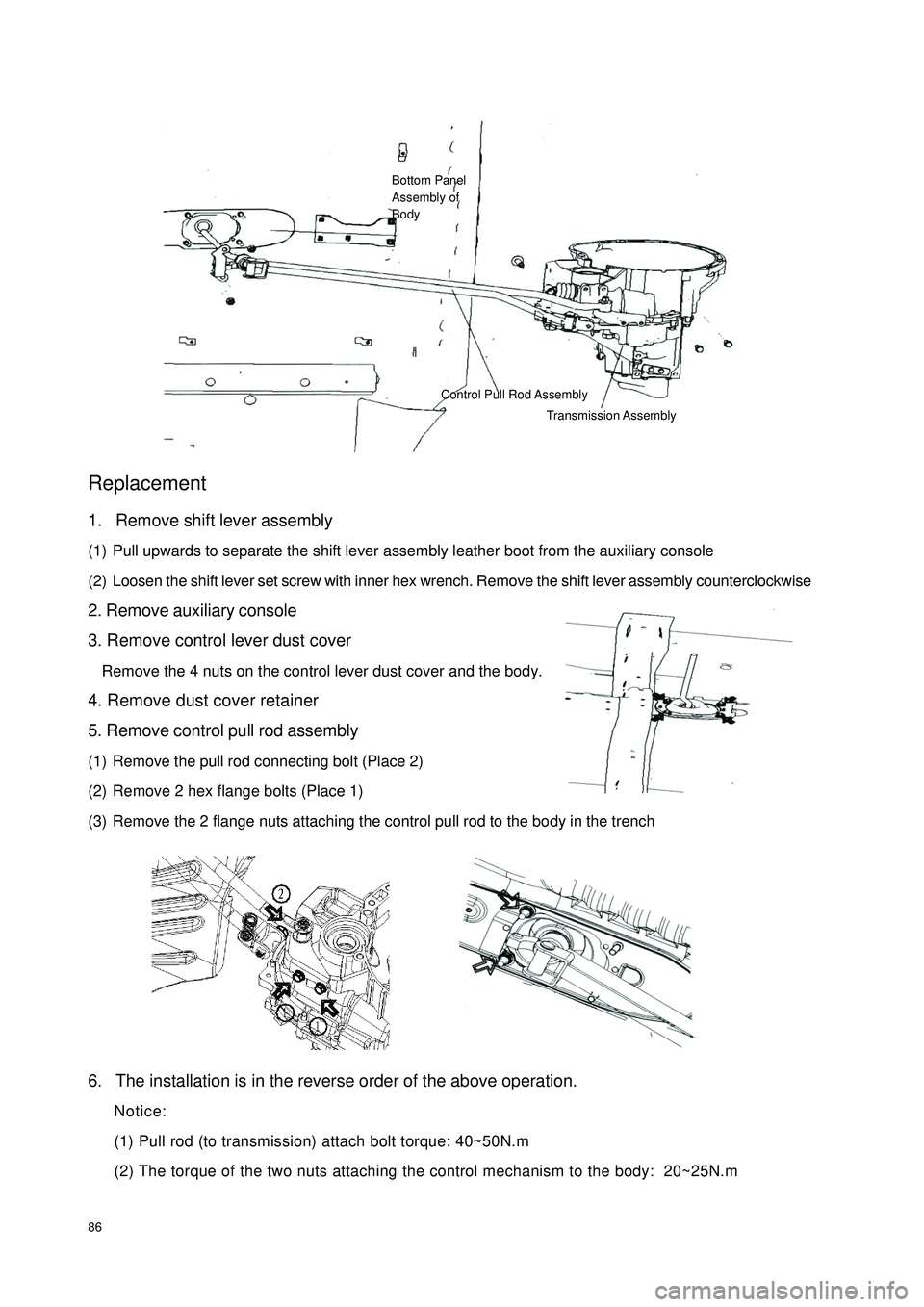
86Replacement1. Remove shift lever assembly
(1) Pull upwards to separate the shift lever assembly leather boot from the auxiliary console
(2) Loosen the shift lever set screw with inner hex wrench. Remove the shift lever assembly counterclockwise
2. Remove auxiliary console
3. Remove control lever dust cover
Remove the 4 nuts on the control lever dust cover and the body.
4. Remove dust cover retainer
5. Remove control pull rod assembly
(1) Remove the pull rod connecting bolt (Place 2)
(2) Remove 2 hex flange bolts (Place 1)
(3) Remove the 2 flange nuts attaching the control pull rod to the body in the trench
6. The installation is in the reverse order of the above operation.
Notice:
(1) Pull rod (to transmission) attach bolt torque: 40~50N.m
(2) The torque of the two nuts attaching the control mechanism to the body: 20~25N.mBottom Panel
Assembly of
BodyControl Pull Rod Assembly
Transmission Assembly
Page 95 of 392
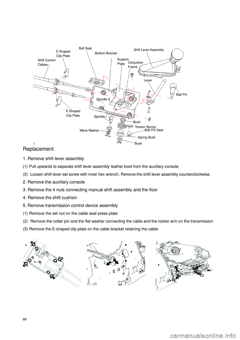
88Replacement1. Remove shift lever assembly
(1) Pull upwards to separate shift lever assembly leather boot from the auxiliary console
(2) Loosen shift lever set screw with inner hex wrench. Remove the shift lever assembly counterclockwise.
2. Remove the auxiliary console
3. Remove the 4 nuts connecting manual shift assembly and the floor
4. Remove the shift cushion
5. Remove transmission control device assembly
(1) Remove the set nut on the cable seal press plate
(2) Remove the cotter pin and the flat washer connecting the cable and the rocker arm on the transmission
(3) Remove the E-shaped clip plate on the cable bracket retaining the cableShift Control
CablesE Shaped
Clip PlateBall SeatShift Lever Assembly LeverBall PinSpindle IISpindle IE Shaped
Clip PlateWave WasherBushBushSpring BushBall Pin Seat Torsion Spring Support
Plate Bottom BracketConjuction
Frame
Page 96 of 392
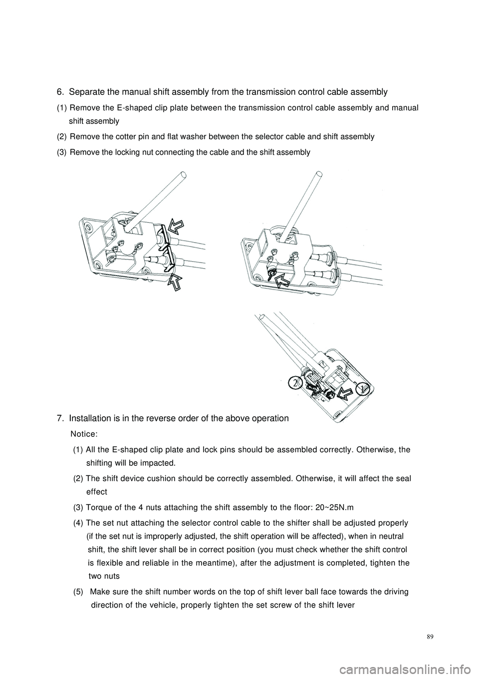
896. Separate the manual shift assembly from the transmission control cable assembly
(1) Remove the E-shaped clip plate between the transmission control cable assembly and manual
shift assembly
(2) Remove the cotter pin and flat washer between the selector cable and shift assembly
(3) Remove the locking nut connecting the cable and the shift assembly
7. Installation is in the reverse order of the above operation
Notice:
(1) All the E-shaped clip plate and lock pins should be assembled correctly. Otherwise, the
shifting will be impacted.
(2) The shift device cushion should be correctly assembled. Otherwise, it will affect the seal
effect
(3) Torque of the 4 nuts attaching the shift assembly to the floor: 20~25N.m
(4) The set nut attaching the selector control cable to the shifter shall be adjusted properly
(if the set nut is improperly adjusted, the shift operation will be affected), when in neutral
shift, the shift lever shall be in correct position (you must check whether the shift control
is flexible and reliable in the meantime), after the adjustment is completed, tighten the
two nuts
(5) Make sure the shift number words on the top of shift lever ball face towards the driving
direction of the vehicle, properly tighten the set screw of the shift lever
Page 99 of 392
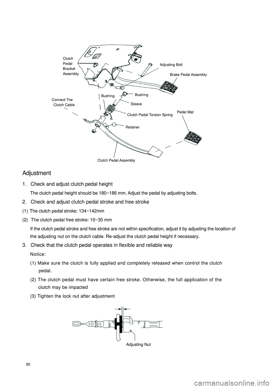
92Adjustment1. Check and adjust clutch pedal height
The clutch pedal height should be 180~186 mm. Adjust the pedal by adjusting bolts.
2. Check and adjust clutch pedal stroke and free stroke
(1) The clutch pedal stroke: 134~142mm
(2) The clutch pedal free stroke: 10~30 mm
If the clutch pedal stroke and free stroke are not within specification, adjust it by adjusting the location of
the adjusting nut on the clutch cable. Re-adjust the clutch pedal height if necessary.
3. Check that the clutch pedal operates in flexible and reliable way
Notice:
(1) Make sure the clutch is fully applied and completely released when control the clutch
pedal.
(2) The clutch pedal must have certain free stroke. Otherwise, the full application of the
clutch may be impacted
(3) Tighten the lock nut after adjustmentConnect The
Clutch CableBushingBushingAdjusting BoltBrake Pedal Assembly Sleeve Clutch Pedal Torsion Spring Retainer Pedal MatClutch Pedal AssemblyClutch
Pedal
Bracket
AssemblyAdjusting Nut
Page 102 of 392
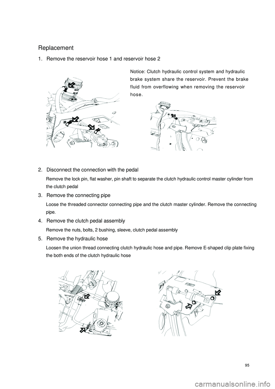
95Replacement1. Remove the reservoir hose 1 and reservoir hose 2
Notice: Clutch hydraulic control system and hydraulic
brake system share the reservoir. Prevent the brake
fluid from overflowing when removing the reservoir
hose.
2. Disconnect the connection with the pedal
Remove the lock pin, flat washer, pin shaft to separate the clutch hydraulic control master cylinder from
the clutch pedal
3. Remove the connecting pipe
Loose the threaded connector connecting pipe and the clutch master cylinder. Remove the connecting
pipe.
4. Remove the clutch pedal assembly
Remove the nuts, bolts, 2 bushing, sleeve, clutch pedal assembly
5. Remove the hydraulic hose
Loosen the union thread connecting clutch hydraulic hose and pipe. Remove E-shaped clip plate fixing
the both ends of the clutch hydraulic hose
Page 106 of 392
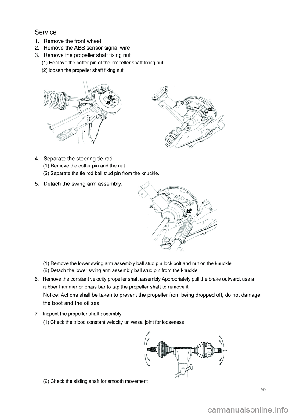
99Service1. Remove the front wheel
2. Remove the ABS sensor signal wire
3. Remove the propeller shaft fixing nut
(1) Remove the cotter pin of the propeller shaft fixing nut
(2) loosen the propeller shaft fixing nut
4. Separate the steering tie rod
(1) Remove the cotter pin and the nut
(2) Separate the tie rod ball stud pin from the knuckle.
5. Detach the swing arm assembly.
(1) Remove the lower swing arm assembly ball stud pin lock bolt and nut on the knuckle
(2) Detach the lower swing arm assembly ball stud pin from the knuckle
6. Remove the constant velocity propeller shaft assembly Appropriately pull the brake outward, use a
rubber hammer or brass bar to tap the propeller shaft to remove itNotice: Actions shall be taken to prevent the propeller from being dropped off, do not damage
the boot and the oil seal7 Inspect the propeller shaft assembly
(1) Check the tripod constant velocity universal joint for looseness
(2) Check the sliding shaft for smooth movement
Page 113 of 392
106Section 3 Front Wheel AlignmentAdjustment1. Inspect tire
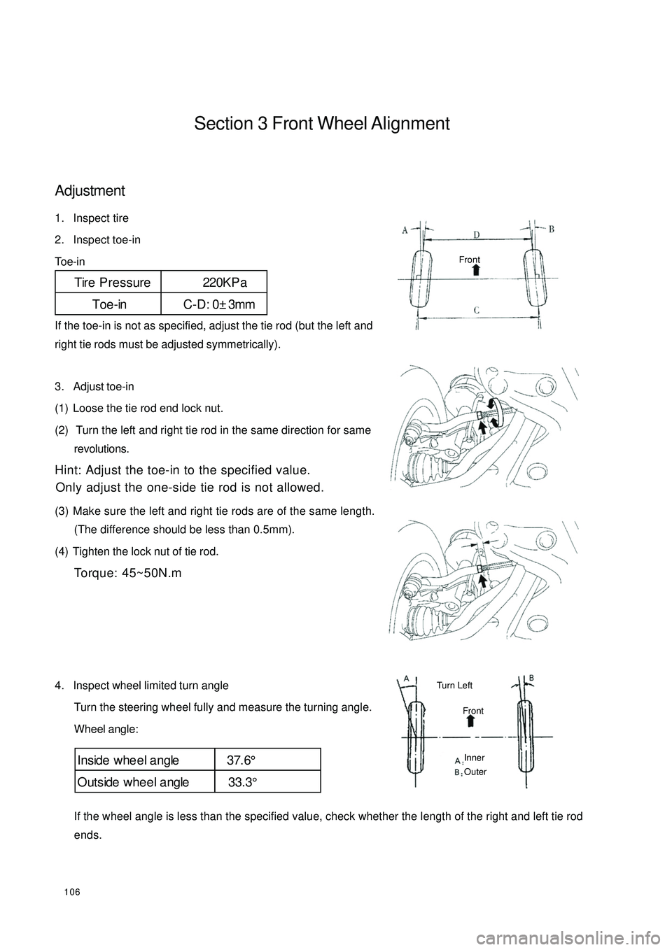
2. Inspect toe-in
Toe-in
If the toe-in is not as specified, adjust the tie rod (but the left and
right tie rods must be adjusted symmetrically).
3. Adjust toe-in
(1) Loose the tie rod end lock nut.
(2) Turn the left and right tie rod in the same direction for same
revolutions.
Hint: Adjust the toe-in to the specified value.
Only adjust the one-side tie rod is not allowed.
(3) Make sure the left and right tie rods are of the same length.
(The difference should be less than 0.5mm).
(4) Tighten the lock nut of tie rod.
Torque: 45~50N.m
4. Inspect wheel limited turn angle
Turn the steering wheel fully and measure the turning angle.
Wheel angle:
If the wheel angle is less than the specified value, check whether the length of the right and left tie rod
ends.Tire Pressure 220KP a
Toe-in C-D: 0±3mmInside whe e l a ngle 37.6°
Outside whee l a ngle 33.3°FrontFrontTurn Left Inner
Outer
Page 139 of 392
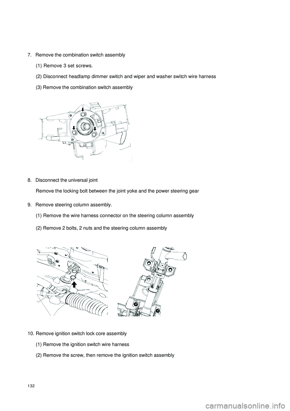
1327. Remove the combination switch assembly
(1) Remove 3 set screws.
(2) Disconnect headlamp dimmer switch and wiper and washer switch wire harness
(3) Remove the combination switch assembly
8. Disconnect the universal joint
Remove the locking bolt between the joint yoke and the power steering gear
9. Remove steering column assembly.
(1) Remove the wire harness connector on the steering column assembly
(2) Remove 2 bolts, 2 nuts and the steering column assembly
10. Remove ignition switch lock core assembly
(1) Remove the ignition switch wire harness
(2) Remove the screw, then remove the ignition switch assembly