lock GEELY CK 2008 Owner's Manual
[x] Cancel search | Manufacturer: GEELY, Model Year: 2008, Model line: CK, Model: GEELY CK 2008Pages: 392, PDF Size: 38.86 MB
Page 140 of 392

13311. Complete the service or replace the steering column assembly, the installation procedure is in the reverseorder of the removal
Notice:
(1) after the installation of the ignition lock core, check the steering lock operation: the
steering mechanism lock when the ignition key is pulled out; the steering mechanism
unlock when the key is inserted and turned to ACC position
(2)The torque of the 2 bolts and 2 nuts securing the steer column assembly:
16~26N.m
(3) connect the wire harness into place and make sure the wiring is good
(4) After properly adjust the positions of the combination switch and the steering column
upper and lower cover, tighten the 3 screws attaching the combination switch and the
steering column
(5) Torque of the universal joint yoke and steering gear assembly locking bolt: 22~34N.m
(6) Torque of the 4 set bolts of the dust cover and press plate: 16~26N.m
(7) When installing the steering wheel assembly, align the matchmarks of the steering wheel
and steering main shaft assembly,
Torque of the steering wheel specific inner torx bolt: 40~60N.m
(7) Check the air bag, it is not allowed to use the air bag parts from another vehicle
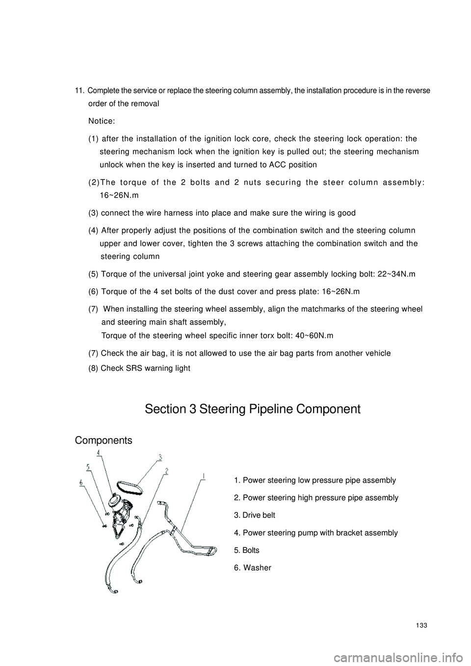
(8) Check SRS warning lightSection 3 Steering Pipeline ComponentComponents1. Power steering low pressure pipe assembly
2. Power steering high pressure pipe assembly
3. Drive belt
4. Power steering pump with bracket assembly
5. Bolts
6. Washer
Page 144 of 392

137Tie Rod RH Ball Stud PinLock NutWire ClipNo.1 BootBandPipeO-ringO-ringO-ringBand
Wire ClipNo. 2 BootLock NutTie Rod LH Ball Stud PinJoint Sub-assemblyJoint Sub-assemblyReplacement1. Drain the power steering system fluid
2. Separate the tie rod from the steering knuckle
(1) Remove the cotter pin, loosen the groove type lock nut
(2) Separate the tie rod ball stud joint from the steering knuckle taper hole
Page 145 of 392

1383. Loosen the union thread of the high and low pressure pipes on the steering gear assembly
4. Remove the boot band and No. 1, No. 2 boots
5. Disconnect the power steering gear assembly from the steering column
Remove the steering gear pinion shaft spline lock bolt on the universal joint yoke
6. Remove power steering gear assembly
Remove 4 steering gear assembly set bolts, remove the power steering gear assembly
7. Installation is in the reverse order of the removal
Notice:
(1) Insert the steering gear pinion shaft spline into the spline hole of the universal joint
yoke, make sure that the positions of the notch of the steering gear pinion shaft and the
lock bolt of the universal joint yoke are correct
(2) Secure the power steering gear with 4 bolts, torque: 63~93N.m
(3) Tighten the steering gear pinion shaft spline lock bolt on the universal joint yoke, torque:
22~34N.m
(4) Tighten the 4 set bolts of the boot band and boot torque: 16~26N.m
(5) Install the union thread of the power steering high and low pressure pipe to the power
steering gear, torque: 19~33N.m
(6) Connect the tie rod ball stud pin with the steering knuckle, make sure that the mating
surface of the tie rod ball stud pin and the steering knuckle is clean, tighten the slot nut,
torque: 27~39N.m. Install the cotter pin, make sure of the correct installation
(7) Add appropriate amount of specified power steering fluid, bleed the power steering sys-
tem
(8) Check the power steering pipeline system for leakage
(9) Check the front wheel alignment and front wheel left and right limit turn angle, adjust the
toe in if necessary and tighten the tie rod lock nut
(10)Check the position of the steering wheel. It is required that the steering wheel spokes
are basically symmetrical when the vehicle is driven straight ahead, reassemble the steering
wheel if necessary
Page 149 of 392

142(3) The 3 bolts connecting the brake pedal support bracket and cowl panel cross member
Torque : 16-20N.m
(4) The 4 bolts connecting the brake pedal support bracket and the vacuum booster with
brake master cylinder assembly
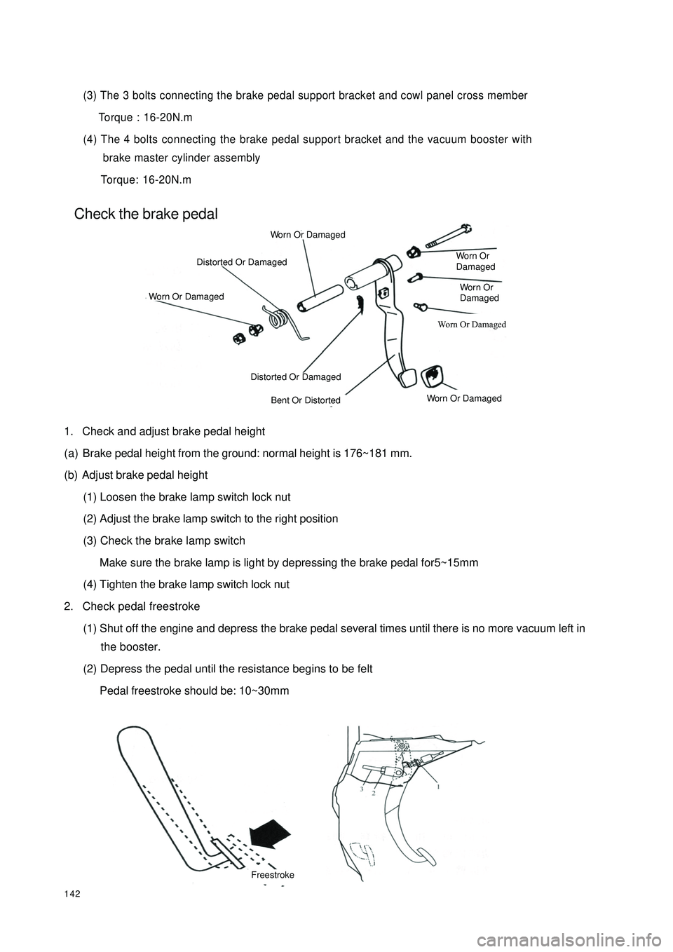
Torque: 16-20N.mCheck the brake pedal1. Check and adjust brake pedal height
(a) Brake pedal height from the ground: normal height is 176~181 mm.
(b) Adjust brake pedal height
(1) Loosen the brake lamp switch lock nut
(2) Adjust the brake lamp switch to the right position
(3) Check the brake lamp switch
Make sure the brake lamp is light by depressing the brake pedal for5~15mm
(4) Tighten the brake lamp switch lock nut
2. Check pedal freestroke
(1) Shut off the engine and depress the brake pedal several times until there is no more vacuum left in
the booster.
(2) Depress the pedal until the resistance begins to be felt
Pedal freestroke should be: 10~30mmWorn Or DamagedWorn Or DamagedWorn Or
DamagedWorn Or
DamagedWorn Or DamagedWorn Or DamagedDistorted Or DamagedDistorted Or DamagedBent Or DistortedFreestroke
Page 203 of 392

196Section 2 Replacement and AdjustmentI WIPER MOTOR ASSEMBLY REPLACEMENT1. REMOVE WIPER MOTOR
(a) Disconnect the connector.
(b) Remove the 4 mounting bolts.
(c) Separate the shaft of the motor crankshaft arm and the wiper link with special tools.
2. INSTALL A NEW WIPER MOTOR
(a) Press the shaft of the motor crankshaft arm and the wiper link in its position with special tools.
(b) Lock the 4 bolts in the specified torque.
(c) Connect the connector.
(d) Operate the wiper, make the washer fluid spraying on the windshield, check if the operation of wiper and
its starting position is normal. If not, remove the wiper arm blades assembly and make some proper
adjustment.
Hint: Make the top of the new shaft of the wiper motor crankshaft arm filled with lubricating oil.II. WIPER BLADES REPLACEMENT1. REMOVE BLADES FROM WIPER BLADES ASSEMBLY 1, 2
�yRemove blades from wiper blades assembly 1, 2 respectively.
2. INSTALL NEW BLADES
�yInstall new blades on wiper blades assembly 1, 2 respectively.4 Mounting Bolts
Page 204 of 392

197III. WIPER SWITCH ASSEMBLY REPLACEMENT1. DETACH STEERING WHEEL ASSEMBLY
(a) Disconnect the main power source of the vehicle.
(b) Remove the passenger SRS module assembly, and cautiously put it in a safe place.
(c) Loosen steering wheel lock-bolts and remove the assembly.
2. REMOVE WIPER SWITCH
(a) Disconnect the connector.
(b) Remove the 2 tapping screws that are for mounting the wiper switch, take out the wiper switch from the
bracket of the combination switch.IV. WASHER NOZZLEADJUSTMENT
1. INSPECT WASHER NOZZLE
(a) Start the engine, check if the position where the washer fluid from the nozzle sprays the windshield is in
the central or upper of the area wiped by the blades.
(b) Change the direction (horizontal) of the nozzle hole to adjust the point where washer fluid sprays the
windshield.
Page 216 of 392

2095. DOOE COURTESY LAMP SWITCH ( ON DOOR LOCK ACTUATOR)
Inspect door courtesy lamp switch for continuity.
Inspect continuity between the terminal and the ground when the switch operates.
If it is not as specified, replace the switch.
6. REAR TRUNK LAMP SWITCH ASSEMBLY
Inspect rear trunk lamp switch for continuity.
Inspect continuity between the terminal and the ground when the switch operates.
If it is not as specified, replace the switch.
7. ROOM LAMP ASSEMBLY
Inspect each terminal on room lamp assembly for continuity.
If it is not as specified, replace the dome lamp or the switch.S w it c h pos it ion T e s t e d t e r mina l C ondit ion
ON 1 – Ground the body Continuity
OFF 1 – Ground the body No c ontinuityTe ste d te rmina l Condition
ON 1-2 Continuity
OFF 1-2 2-3 No continuity
DOOR (The door is a jar) 2-3 Continuity
DOOR (The door is c lose d) 2-3 No continuity
ON (Switc h is pre ssed) 1-2 Continuity
OFF 1-2 No continuity Switc h position
Interior dome la mp
LR and RR reading lampsSwitch position Tested terminal Condition
ON (The door is we ll close d) 1 – Ground the body Continuity
OFF (The door is aja r) 1 – Ground the body No c ontinuity1
2
3
Page 219 of 392

212II.INSTALLATION1. Install the electrical connector of the headlamp assembly.
2. Install the headlamp assembly and the 3 mounting bolts.
3. Install the front bumper.
4. Adjust the condition of the vehicle.
5. Adjust the headlamp beam.III.HEADLAMP BULB REPLACEMENT1 - LOW BEAM DUST COVER 2 - HIGH BEAM DUST COVER 3 - TURN SIGNAL LAMP DUST
COVER 4 - HEADLAMP HOLDER
1. Replace the high and low beam bulbs
�y Turn and remove the dust cover counter-clockwise
�y Pull out the bulb plug
�y Press and release the wire clip
�y Pull out the lamp-holder, and remove the bulb
�y Replace the bulb
2. Replace the turn signal lamp bulbs
�y Remove the 3 screws on the dust cover with screwdriver
�yTurn the lamp-holder counter-clockwise. Pull out the lamp-holder, and remove the bulb
�yReplace the bulb
3. Replace the headlamp bulbs
�yTurn the lamp-holder counter-clockwise. Pull out the lamp-holder, remove the bulb, and replace the
bulb.1 2 3 4
Page 222 of 392

215Section 4 Front Fog Lamp ReplacementI. REMOVAL1. Remove the front bumper.(See bumper replacement)
2. Remove the electrical connector.
3. Remove the mounting bolts (A, B as shown in the illustration).
4. Remove the front fog lamp assembly.II. INSTALLATION1. Install the front fog lamp assembly.
2. Install the mounting bolts.
3. Install the electrical connector.
4. Install the front bumper.
5. Adjust the condition of the vehicle.
6. Adjust the front fog lamp beam.III. FRONT FOG LAMP BULB REPLACEMENT1. Press and Turn counter-clockwise, then remove the dust cover
2. Pull out the bulb
3. Replace the bulbABElectrical
Connection
Page 223 of 392

216IV. FRONT FOG LAMP BEAM ADJUSTMENT1. Adjust the tire inflation pressure with the standard value
2. Start the engine
3. Turn the fog lamp switch ON
4. Adjust the fog lamp beam.
Turn the bolt A for adjusting fog lamp beam in vertical direction.
NOTES:
Turn the screwdriver counter-clockwise to make the light beam up, clockwise make the light beam down.