belt GEELY CK 2008 Owner's Manual
[x] Cancel search | Manufacturer: GEELY, Model Year: 2008, Model line: CK, Model: GEELY CK 2008Pages: 392, PDF Size: 38.86 MB
Page 38 of 392

31Replacement1. Disconnect all the wire harnesses and the cables on the engine connected to the car body.
2. Detach air filter assembly with hose
3. Disconnect oil pipe and water hose
4. Loose positive and negative cables of the battery.
5. Detach propeller shaft. Detach front exhaust pipe assembly
6. Loose engine left & right rear brackets after hoisting the engine.
7. Disconnect all the other connectors between the engine and the car body.
8. See "Provision 20, Section 2, Chapter 2". Lift the car body and take out the engine assembly.
9. Remove A/C compressor to the crankshaft pulleyV-belt.
10. Remove power steering pump V-belt.
11. Detach water pump fan pulley.
12. Disconnect ignition coil and high voltage cable.
13. Detach cylinder head cover sub-assembly.
14. Detach generator assembly.
15. Detach the camshaft.
16. Detach the throttle body assembly
17. Detach intake manifold stay No. 2.
18. Take out the dipstick
19. Detach No. 1 fuel delivery pipe
20. Detach the wire harness.
21. Detach the steering assisting pump assembly
22. Detach exhaust manifold. See (Figure 71)
23. Pry cylinder head from the dowel pin on the cylinder block.
See (Figure 72)
24. Remove the cylinder head gasket.
25. Install cylinder head gasket
26. Install cylinder head sub-assembly
27. Install exhaust pipe assembly.
(a) Install the new gasket and exhaust manifold with 5
bolts. Torque: 34N. m
(b) Install exhaust manifold stay with 2 bolts.
(c) Install upper heat shield with 4 bolts
Torque: 17N. mFigure 71
Figure 72
Page 40 of 392

33Section 6 Oil Pump Oil Seal Replacement1. Pry with 2 screwdrivers. Detach crankshaft timing pulley.
See (Figure 74)
2. Remove oil pump oil seal. See (Figure 75)
(a) Using a knife, cut off oil seal lip.
(b) Using a screwdriver, pry out the oil seal.
3. Install oil pump oil seal. See (Figure 76)
(a) Smear grease to a new oil seal lip.
(b) on the oil seal with hammer until the edge of the oil pump
case is filled with the seal packing.
4. Install crankshaft timing pulley. See (Figure 77)
(a) Align pulley set key to the key groove.
(b) Place the flange face inward. Install timing pulley.
5. Install timing belt
6. Check engine oil for leakage
Figure 76 Figure 74
Figure 75
Figure 77
Page 43 of 392

36Section 2 Oil Pump Assembly Replacement1. Remove timing belt
2. Remove timing belt idler sub-assembly
3. Detach crankshaft timing pulley. See (Figure 74)
4. Remove the dipstick guide
5. Detach oil sump sub-assembly. See (Figure 83)
6. Detach oil strainer sub-assembly. See (Figure 84)
7. Detach oil pump assembly. See (Figure 85)
8. Remove oil pump oil seal
9. Install oil pump oil seal
10. Install oil pump assembly
11. Install oil strainer sub-assembly
12. Install oil sump assembly. See (Figure 86)
Figure 84
Figure 85Figure 83Figure 86
Page 44 of 392

3713. Install the dipstick guide. See (Figure 87)
14. Install crankshaft timing pulley. See (Figure 77)
15. Install timing belt idler sub-assembly No.1
16. Install timing belt
17. Fill in engine oil
18. Check oil for leakage
Figure 87
Page 47 of 392

40Section 5 Generator Replacement1. Detach V-belt of generator
2. Detach generator assembly
(a) Disconnect wire joint of generator.
(b) Remove wire of generator.
(c) Disconnect oil pressure switch interface.
(d) Disconnect A/C compressor switch connector.
(e) Open wire clips.
(f) Detach 2 bolts and generator.
3. Install generator assembly
Torque:
M12 bolt 18N. m
M14 bolt 58N. m
4. Transmit belt tilt and tension state inspection
Page 61 of 392

54Section 2 Water Pump, Thermostat and Radiator ReplacementHoist the engine from the compartment. See "Provison 20, Section 2, Chapter 2".
1. Replace water pump. See (Figure 125)
(1) Drain the coolant.
(2) Detach timing belt.
(3) Detach power steering pump assembly.
(4) Remove the oil dipstick guide.
(5) Detach water pump assembly.
(6) Install water pump assembly.
(7) The installation is in the reverse order of the removal.
2. Replace thermostat
(1) Remove thermostat (See Figure 126).
(2) Install thermostat.
a. Install a new gasket to the thermostat. See (Figure 127).
b.Align the main valve of the thermostat to the top of the
stud. Insert the thermostat into the water inlet case.
Hint:
The main valve is set at around 10°C as shown in the figure. See (Figure 128).
(3) Install inlet connector.
Figure 127 Figure 128
3. Replace radiator
(1) Open radiator cap.
(2) Open the drain valve and drain the coolant.
(3) Detach radiator water inlet hose.
(4) Detach radiator water outlet hose.Figure 125
Figure 126
Page 140 of 392

13311. Complete the service or replace the steering column assembly, the installation procedure is in the reverseorder of the removal
Notice:
(1) after the installation of the ignition lock core, check the steering lock operation: the
steering mechanism lock when the ignition key is pulled out; the steering mechanism
unlock when the key is inserted and turned to ACC position
(2)The torque of the 2 bolts and 2 nuts securing the steer column assembly:
16~26N.m
(3) connect the wire harness into place and make sure the wiring is good
(4) After properly adjust the positions of the combination switch and the steering column
upper and lower cover, tighten the 3 screws attaching the combination switch and the
steering column
(5) Torque of the universal joint yoke and steering gear assembly locking bolt: 22~34N.m
(6) Torque of the 4 set bolts of the dust cover and press plate: 16~26N.m
(7) When installing the steering wheel assembly, align the matchmarks of the steering wheel
and steering main shaft assembly,
Torque of the steering wheel specific inner torx bolt: 40~60N.m
(7) Check the air bag, it is not allowed to use the air bag parts from another vehicle
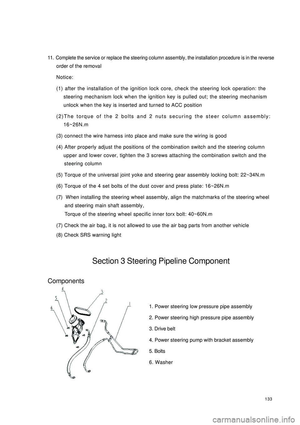
(8) Check SRS warning lightSection 3 Steering Pipeline ComponentComponents1. Power steering low pressure pipe assembly
2. Power steering high pressure pipe assembly
3. Drive belt
4. Power steering pump with bracket assembly
5. Bolts
6. Washer
Page 141 of 392

134On-vehicle inspection1. check the drive belt
Observe the drive belt for excessive wear and cordline wear. Replace the drive belt if necessary.
Hint: Cracks on the rib side of a belt are considered acceptable. If missing chunks from the
ribs are found on the drive belt, it should be replaced.
2. Bleed the power steering system
(1) Check the fluid level
(2) Jack up the front of the vehicle and make sure it is safe
(3) Rotate the steering wheel
a. With the engine off, turn the steering wheel from LH limit position to RH limit position several
times
(4) Release the jack and lower the vehicle
(5) Start the engine, run the engine at idle for a few minutes
(6) Turn the steering wheel to left or right limit position and keep it there for 2 - 3 seconds, then turn the
steering wheel to the opposite limit position and keep it there for 2 - 3 seconds. Repeat it several
times.
(7) Shut off the engine, check for foaming or emulsification in the reservoir. If there is foaming or
emulsification, bleed power steering system repeatedly
(8) Check the fluid level and for leakage
2. Check the fluid level
(1) Park the vehicle on a level surface
(2) With the engine stopped, check the fluid level in the reservoir. Add power steering fluid AT F
DEXRON if necessary.
Hint: the fluid level should be within the range of lowest level and highest level
(3) Check for foaming or emulsification, if there is, drain the power steering systemNormalAbnormal
Page 142 of 392

135Replacement1. Drain the power steering system fluid
2. Remove the power steering high and low pressure pipe
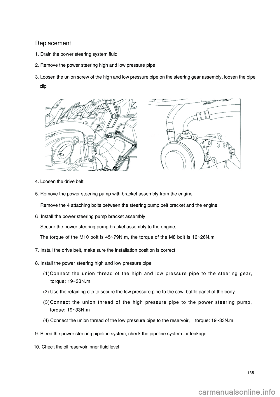
3. Loosen the union screw of the high and low pressure pipe on the steering gear assembly, loosen the pipe
clip.
4. Loosen the drive belt
5. Remove the power steering pump with bracket assembly from the engine
Remove the 4 attaching bolts between the steering pump belt bracket and the engine6.Install the power steering pump bracket assemblySecure the power steering pump bracket assembly to the engine,
The torque of the M10 bolt is 45~79N.m, the torque of the M8 bolt is 16~26N.m7. Install the drive belt, make sure the installation position is correct
8. Install the power steering high and low pressure pipe(1)Connect the union thread of the high and low pressure pipe to the steering gear,
torque: 19~33N.m
(2) Use the retaining clip to secure the low pressure pipe to the cowl baffle panel of the body
(3)Connect the union thread of the high pressure pipe to the power steering pump,
torque: 19~33N.m
(4) Connect the union thread of the low pressure pipe to the reservoir, torque: 19~33N.m
9. Bleed the power steering pipeline system, check the pipeline system for leakage
10. Check the oil reservoir inner fluid level
Page 174 of 392

1673. INSPECT DRIVE BELT
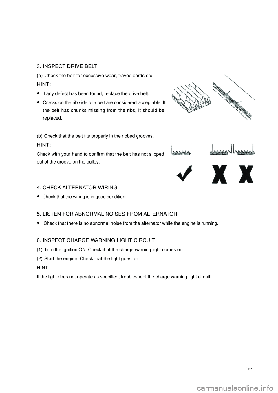
(a) Check the belt for excessive wear, frayed cords etc.
HINT:
�yIf any defect has been found, replace the drive belt.
�yCracks on the rib side of a belt are considered acceptable. If
the belt has chunks missing from the ribs, it should be
replaced.
(b) Check that the belt fits properly in the ribbed grooves.
HINT:
Check with your hand to confirm that the belt has not slipped
out of the groove on the pulley.
4. CHECK ALTERNATOR WIRING
�yCheck that the wiring is in good condition.
5. LISTEN FOR ABNORMAL NOISES FROM ALTERNATOR
�y Check that there is no abnormal noise from the alternator while the engine is running.
6. INSPECT CHARGE WARNING LIGHT CIRCUIT
(1) Turn the ignition ON. Check that the charge warning light comes on.
(2) Start the engine. Check that the light goes off.
HINT:
If the light does not operate as specified, troubleshoot the charge warning light circuit.