ECU GEELY CK 2008 Manual PDF
[x] Cancel search | Manufacturer: GEELY, Model Year: 2008, Model line: CK, Model: GEELY CK 2008Pages: 392, PDF Size: 38.86 MB
Page 301 of 392

294III. HCU Replacement1. Depress the retaining clip on the union joint side
and remove the cylinder motor wire harness.
2. Remove the 4 screws as shown in the figure, the
removed old screw can not be reused.
3. Separate the HCU from the ECU.
4. Install the new HCU to the ECU.
5. Use new screw to attach the ECU to the HCU,
tighten the torque: 3+1Nm.
6. Connect the motor wire harness, be careful that
the retaining clip shall be in place.IV. ECU Replacement1. Depress the retaining clip on the union joint side and remove the
wire harness.
2. Remove the 4 screws as shown in the figure and discard them
3. Remove the HCU from the ECU.
4. Install the new ECU to the HCU.
5. Use the new screw to attach the ECU to the HCU, tighten the
torque3+1Nm.
6. Connect the motor wire harness, be careful that the retaining clip
shall be in place.
Page 302 of 392

295V. ABS Assembly ReinstallationNote: the plug of the ABS assembly hydraulic outlet can only be removed after the brake pipe is
installed, lest the foreign object will enter the brake system.1. Install the ABS assembly to the bracket, tighten the torque: 20+4Nm.
2. Remove the plug of the hydraulic outlet, installed the brake pipe. Make sure that the brake pipe is
correctly installed.
3. Install the brake pipe connected to the master cylinder.
4. The brake pipe torque is 12+4Nm (M10 x 1) and 15+3Nm (M12 x 1).
5. Fill the new brake fluid into the reservoir until the liquid level reach the MAX and bleed it as specified.
6. With the ignition switch ON, ABS Warning Light must goes on for 1.7 seconds then goes off.
7. Clear the DTC memory, check if there is DTC again.
8. Drive the vehicle to confirm the ABS function (you must feel that the pedal rebound).VI. ECU ProgramNote: when replacing the HECU or ECU, you shall program the new ECU, otherwise the ABS
Warning Light flashes and the system can not operate normally.Use the scan meter to program the ECU based on the following procedure:Connect the scan meter with the diagnostic interfaceSelect function 07, Press OK button to confirmEnter code 01901 and Press OK button to confirmSelect function 07, Press OK button to confirm, quit the diagnosticEnd
Page 303 of 392

296VII. Fill the liquid and bleedAfter replacing the HECU, bleed the second HECU circuit in addition to the filling and bleeding of the regular
brake system. Use the scan meter to perform the following procedure:Fill the fluid and bleed based on the regular brake system
until there is no air bubble in the transparent hoseConnect the scan meter with the diagnostic interfaceSelect function 04, Press OK button to confirmDepress the brake pedal and keep the hydraulic cylinder pushrod reboundRelease the brake pedal, loosen the left and right brake caliperbleeder screw, press "" buttonDepress the brake pedal 10 times, tighten the left and right
brake caliper bleeder screw, press "" buttonRepeat the above I II III steps 7 times and press "" buttonThe screen display the end of the bleed, press
"" button to return to "function selection" menuSelect function 06, Press OK button to confirm, quit the
diagnostic modeEnd →↑
↑
↑
Page 309 of 392

302Section 3 A/C controlling systemI. Introduction and CompositionIn order to ensure the effective opeation of the A/C system in any operating condition, some advanced
electric control devices are used to protect the A/C system in adverse engine operating condition.
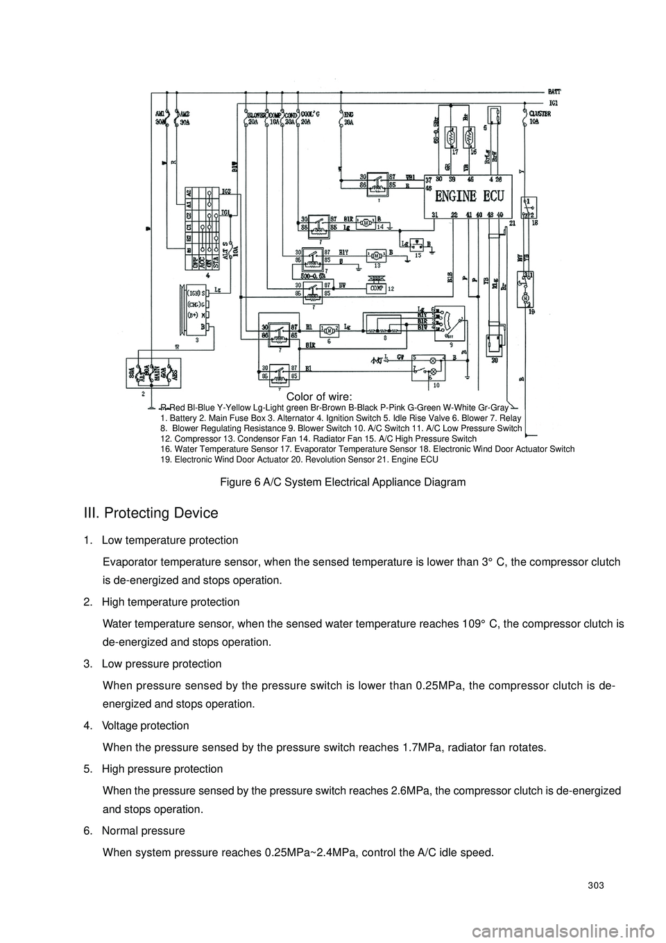
The electrical control part consists of: A/C switch, relay, evaporator temperature sensor, water temperature
sensor, pressure switch, ECU...etc.
A/C system circuit diagram is shown in Figure 6.II. controlling system feature(1) The condenser fan's power is 90W;
(2) The performance of the condenser fan is controlled by ECU, pressure switch;
(3) Cut off the electrical power of the A/C compressor clutch when the water temperature reaches 109°C;
(4) Connect blower switch 9 to rotate the blower motor 6 to ensure A/C normal operation. Connect A/C
switch 10 to output A/C request signal to ECU.
(5) After ECU receives the request signal and the one from the evaporator temperature sensor 17, if the
engine is at idle, ECU first increases the engine speed to 950 ± 50r/min, lest the A/C operation enhance
the load and lower the engine speed or result in engine off. And then the ECU can respond. If the engine
is in accelerating condition, ECU does not respond immediately either, and respond 5 seconds later after
the end of the accelerating condition. ECU send out a A/C control signal from pin 22 to relay 7, command
the relay to suction in. With the low pressure switch 11 closed, the compressor 12 starts to work when the
magnetic clutch suction on. The condenser relay holds in and condenser blower 13 rotates. When high
pressure switch 15 is closed, have the relay 7 hold in and the water tank fan 14 rotates. When the water
temperature sensor 16's temperature is higher than 109°C, ECU shut off the output signal of the pin 22
and A/C stops operation.
(6) When the Refrigeration system pressure is over 1.7MPa, radiator fan will rotato. Disconnect A/C
compressor Refrigeration system power supply when the pressure is over 2.6MPa or less than 0.25MPa;
Page 310 of 392

303Figure 6 A/C System Electrical Appliance DiagramIII. Protecting Device1. Low temperature protection
Evaporator temperature sensor, when the sensed temperature is lower than 3°C, the compressor clutch
is de-energized and stops operation.
2. High temperature protection
Water temperature sensor, when the sensed water temperature reaches 109°C, the compressor clutch is
de-energized and stops operation.
3. Low pressure protection
When pressure sensed by the pressure switch is lower than 0.25MPa, the compressor clutch is de-
energized and stops operation.
4. Voltage protection
When the pressure sensed by the pressure switch reaches 1.7MPa, radiator fan rotates.
5. High pressure protection
When the pressure sensed by the pressure switch reaches 2.6MPa, the compressor clutch is de-energized
and stops operation.
6. Normal pressure
When system pressure reaches 0.25MPa~2.4MPa, control the A/C idle speed. Color of wire:R-Red Bl-Blue Y-Yellow Lg-Light green Br-Brown B-Black P-Pink G-Green W-White Gr-Gray
1. Battery 2. Main Fuse Box 3. Alternator 4. Ignition Switch 5. Idle Rise Valve 6. Blower 7. Relay
8. Blower Regulating Resistance 9. Blower Switch 10. A/C Switch 11. A/C Low Pressure Switch
12. Compressor 13. Condensor Fan 14. Radiator Fan 15. A/C High Pressure Switch
16. Water Temperature Sensor 17. Evaporator Temperature Sensor 18. Electronic Wind Door Actuator Switch
19. Electronic Wind Door Actuator 20. Revolution Sensor 21. Engine ECU
Page 321 of 392

314Have a focus inspection on the following area:
a. Each pipe union joint and valve connection.
b. All hose, especially near the pipe union.
c. Compressor shaft seal, front and rear cover, gasket, oil fill plug.
d. Area on the surface of the condenser and evaporator that is scratched, bruised or damaged.
e. Expansion valve inlet and outlet connection and temperature sensor element and the welding position.
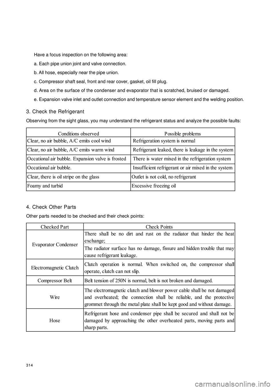
3. Check the Refrigerant
Observing from the sight glass, you may understand the refrigerant status and analyze the possible faults:
4. Check Other Parts
Other parts needed to be checked and their check points:Conditions obse rvedP ossible proble ms
Cle ar, no a ir bubble , A/C e mits c ool wind Re frige ra tion system is normal
Cle ar, no a ir bubble , A/C e mits warm wind Re frige ra nt le a ke d, the re is le aka ge in the syste m
Occ a tiona l a ir bubble . Expa nsion va lve is froste d There is wa te r mixe d in the re frigeration syste m
Occational air bubble. Insufficient refrigerant or air mixed in the system
Cle ar, the re is oil stripe on the gla ss Outle t is not c old, no refrige ra nt
Foamy and turbid Excessive freezing oilChecked PartCheck Points
The re sha ll be no dirt and rust on the radiator tha t hinde r the he at
exchange;
The ra dia tor surfa ce ha s no da mage , fissure a nd hidde n trouble tha t ma y
cause refrigerant leakage.
Elec tromagne tic Clutc hClutc h ope ration is norma l. Whe n switche d on, the c ompre ssor sha ll
operate, clutch can not slip.
Compre ssor Be lt Be lt te nsion of 250N is normal, belt is not broke n and dama ged.
WireThe electromagnetic clutch and blower power cable shall be not damaged
and overheated; the connection shall be reliable, and the protective
gromme t through the me tal plate sha ll be ke pt good a nd without da ma ge .
HoseRefrigerant hose and condenser pipe shall be secured and shall not be
dama ged by a pproac hing the othe r ove rhe ate d pa rts, moving pa rts a nd
sha rp parts. Eva pora tor Conde nse r