fuse box diagram GEELY CK 2008 Workshop Manual
[x] Cancel search | Manufacturer: GEELY, Model Year: 2008, Model line: CK, Model: GEELY CK 2008Pages: 392, PDF Size: 38.86 MB
Page 233 of 392

226II. Inspection1. Power switch system doesn't work
Wiring Diagram
(1) Check radio assembly (+B, ¬ACC, ¬GND)
1Check the continuity between terminals under each operating condition as shown in the table below
Standard:
2Check the voltage between terminals under each operating condition as shown in the table
Standard:
Normal:Repair or replace wire harness, connector
Abnormal:Check or replace radio assemblyMain Fuse BoxRadio and CD
BatteryFusible Link BoxIgnition SwitchTester connection Condition Standard Status
GND Consta nt Status ContinuityTeste r Connec tion Condition Sta nda rd Sta tus
+B - GND Consta nt Status 10~
14V
ACC - GND Ignition switch ACC or ON 10~
14V
Page 234 of 392

2272. The radio backlight does not light up with the illumination switch ON
Wiring Diagram
(1) Check radio assembly (TAIL)
Check the voltage between terminals under each operating condition as shown in the table below.
Standard:
Abnormal:Repair or replace wire harness and connector
Normal:Check and replace radio assemblyMain Fuse BoxRadio and CDFusible Link Box
BatteryLight
Control
Switch
BatteryTeste r Connec tion Condition Sta nda rd Sta tus
TAIL - GND Combined Switch (Light switc h) 10~
14V
Page 235 of 392

2283. Speaker soundless in all modes
Wiring Diagram
(1) Check LCD (Liquid Crystal Display) illumination
1Turn ignition switch to ACC
2Connect radio assembly continuity
3Switch on position lamp
Standard: Radio assembly LCD light goes on
Abnormal:Go to Step (7)
Normal:Go to Next Step
(2) Control volume and adjust volume balance
�yOperate the radio assembly to adjust volume balance and find soundless speaker
Check and replace the radio assembly if all the speakers are soundless
Check and replace the soundless speakers if some of the speakers are soundlessMain Fuse BoxRadio and CDIgnition switchFusible Link BoxBatteryLeft Rear SpeakerRight Rear SpeakerLeft tweeter SpeakerRight tweeter SpeakerLeft Front Speaker
Right Front Speaker
Page 310 of 392

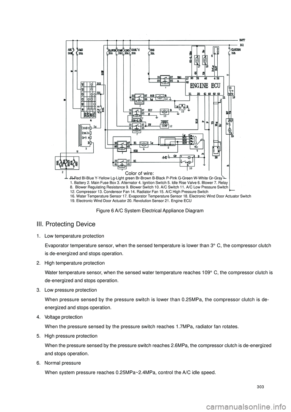
303Figure 6 A/C System Electrical Appliance DiagramIII. Protecting Device1. Low temperature protection
Evaporator temperature sensor, when the sensed temperature is lower than 3°C, the compressor clutch
is de-energized and stops operation.
2. High temperature protection
Water temperature sensor, when the sensed water temperature reaches 109°C, the compressor clutch is
de-energized and stops operation.
3. Low pressure protection
When pressure sensed by the pressure switch is lower than 0.25MPa, the compressor clutch is de-
energized and stops operation.
4. Voltage protection
When the pressure sensed by the pressure switch reaches 1.7MPa, radiator fan rotates.
5. High pressure protection
When the pressure sensed by the pressure switch reaches 2.6MPa, the compressor clutch is de-energized
and stops operation.
6. Normal pressure
When system pressure reaches 0.25MPa~2.4MPa, control the A/C idle speed. Color of wire:R-Red Bl-Blue Y-Yellow Lg-Light green Br-Brown B-Black P-Pink G-Green W-White Gr-Gray
1. Battery 2. Main Fuse Box 3. Alternator 4. Ignition Switch 5. Idle Rise Valve 6. Blower 7. Relay
8. Blower Regulating Resistance 9. Blower Switch 10. A/C Switch 11. A/C Low Pressure Switch
12. Compressor 13. Condensor Fan 14. Radiator Fan 15. A/C High Pressure Switch
16. Water Temperature Sensor 17. Evaporator Temperature Sensor 18. Electronic Wind Door Actuator Switch
19. Electronic Wind Door Actuator 20. Revolution Sensor 21. Engine ECU