check engine GEELY CK 2008 Workshop Manual
[x] Cancel search | Manufacturer: GEELY, Model Year: 2008, Model line: CK, Model: GEELY CK 2008Pages: 392, PDF Size: 38.86 MB
Page 2 of 392
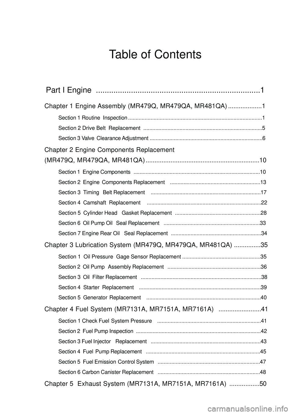
Table of ContentsPart I Engine ...........................................................................1Chapter 1 Engine Assembly (MR479Q, MR479QA, MR481QA)...................1Section 1 Routine Inspection.........................................................................................1
Section 2 Drive Belt Replacement ...............................................................................5
Section 3 Valve Clearance Adjustment...........................................................................6Chapter 2 Engine Components Replacement
(MR479Q, MR479QA, MR481QA)................................................................10Section 1 Engine Components....................................................................................10
Section 2 Engine Components Replacement............................................................13
Section 3 Timing Belt Replacement.........................................................................17
Section 4 Camshaft Replacement............................................................................22
Section 5 Cylinder Head Gasket Replacement.........................................................28
Section 6 Oil Pump Oil Seal Replacement................................................................33
Section 7 Engine Rear Oil Seal Replacement............................................................34Chapter 3 Lubrication System (MR479Q, MR479QA, MR481QA)...............35Section 1 Oil Pressure Gage Sensor Replacement....................................................35
Section 2 Oil Pump Assembly Replacement..............................................................36
Section 3 Oil Filter Replacement................................................................................38
Section 4 Starter Replacement.................................................................................39
Section 5 Generator Replacement............................................................................40Chapter 4 Fuel System (MR7131A, MR7151A, MR7161A)........................41Section 1 Check Fuel System Pressure.....................................................................41
Section 2 Fuel Pump Inspection...................................................................................42
Section 3 Fuel Injector Replacement.........................................................................43
Section 4 Fuel Pump Replacement............................................................................45
Section 5 Fuel Emission Control System....................................................................47
Section 6 Carbon Canister Replacement....................................................................48Chapter 5 Exhaust System (MR7131A, MR7151A, MR7161A).................50
Page 3 of 392
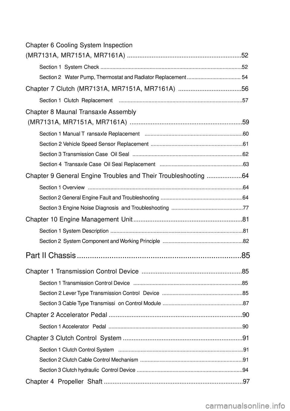
Chapter 6 Cooling System Inspection
(MR7131A, MR7151A, MR7161A).................................................................52Section 1 System Check
Section 2 Water Pump, Thermostat and Radiator Replacement.................................... 54Chapter 7 Clutch (MR7131A, MR7151A, MR7161A)....................................56Section 1 Clutch Replacement...................................................................................57Chapter 8 Maunal Transaxle Assembly
(MR7131A, MR7151A, MR7161A)................................................................59Section 1 Manual Transaxle Replacement..................................................................60
Section 2 Vehicle Speed Sensor Replacement
Section 3 Transmission Case Oil Seal..........................................................................62
Section 4 Transaxle Case Oil Seal Replacement........................................................63Chapter 9 General Engine Troubles and Their Troubleshooting....................64Section 1 Overview........................................................................................................64
Section 2 General Engine Fault and Troubleshooting.......................................................64
Section 3 Engine Noise Diagnosis and Troubleshooting................................................77Chapter 10 Engine Management Unit..............................................................81Section 1 System Description.........................................................................................81
Section 2 System Component and Working Principle......................................................82Part II Chassis............................................................................85Chapter 1 Transmission Control Device.........................................................85Section 1 Transmission Control Device.........................................................................85
Section 2 Lever Type Transmission Control Device......................................................85
Section 3 Cable Type Transmission Control Module......................................................87Chapter 2 Accelerator Pedal............................................................................90Section 1 Accelerator Pedal..........................................................................................90Chapter 3 Clutch Control System....................................................................91Section 1 Clutch Control System....................................................................................91
Section 2 Clutch Cable Control Mechanism.....................................................................91
Section 3 Clutch hydraulic Control Device.......................................................................94Chapter 4 Propeller Shaft...............................................................................97...............................................................................................52
..............................................................61
Page 6 of 392
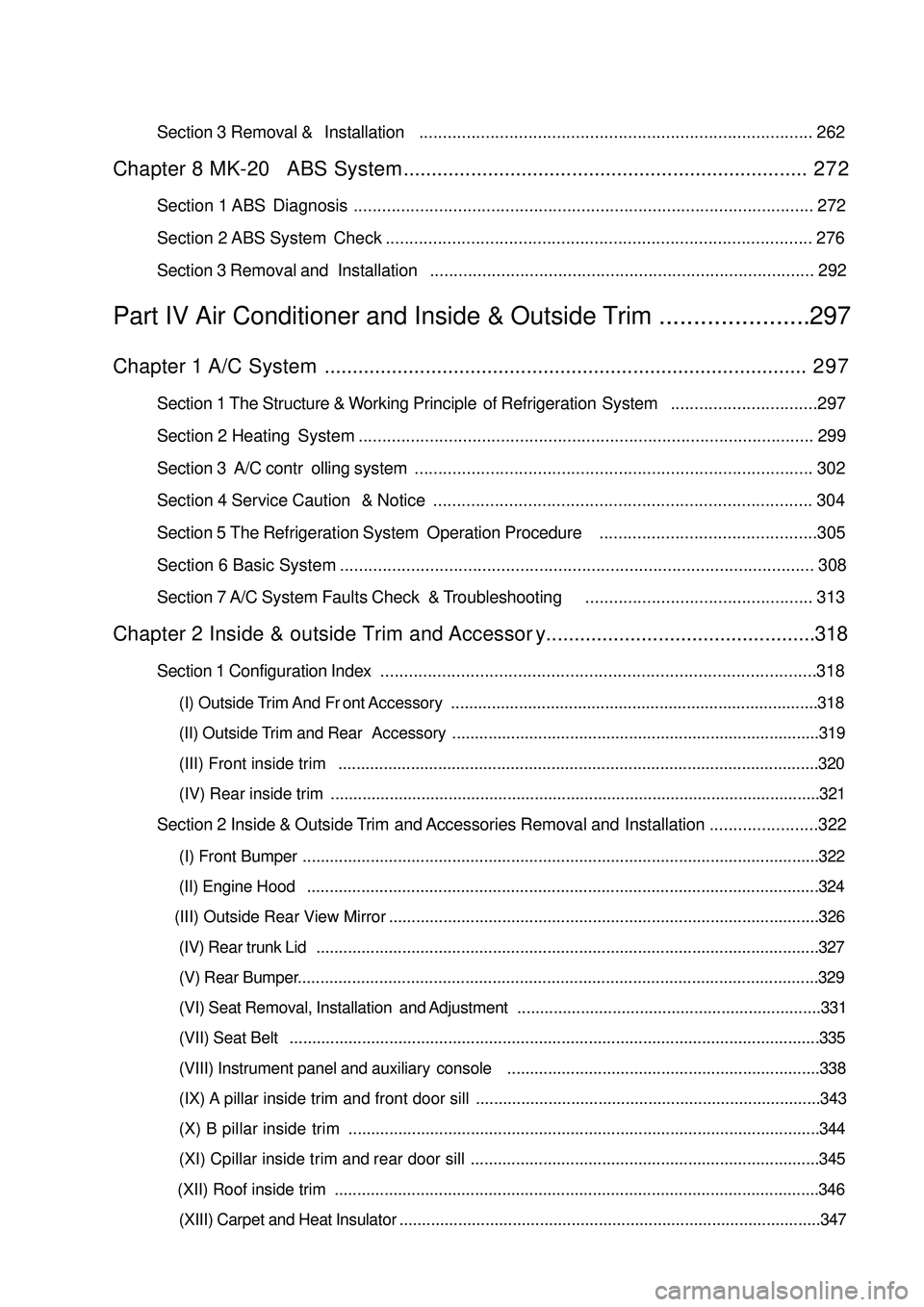
Section 3 Removal & Installation................................................................................... 262Chapter 8 MK-20 ABS System........................................................................ 2 7 2Section 1 ABS Diagnosis ................................................................................................. 272
Section 2 ABS System Check .......................................................................................... 276
Section 3 Removal and Installation................................................................................. 292Part IV Air Conditioner and Inside & Outside Trim ......................297Chapter 1 A/C System...................................................................................... 2 9 7Section 1 The Structure & Working Principle of Refrigeration System...............................297
Section 2 Heating System ................................................................................................ 299
Section 3 A/C controlling system.................................................................................... 302
Section 4 Service Caution & Notice................................................................................ 304
Section 5 The Refrigeration System Operation Procedure..............................................305
Section 6 Basic System .................................................................................................... 308
Section 7 A/C System Faults Check & Troubleshooting................................................ 313Chapter 2 Inside & outside Trim and Accessory................................................318Section 1 Configuration Index............................................................................................318(I) Outside Trim And Front Accessory.................................................................................318
(II) Outside Trim and Rear Accessory.................................................................................319
(III) Front inside trim..........................................................................................................320
(IV) Rear inside trim ............................................................................................................321Section 2 Inside & Outside Trim and Accessories Removal and Installation.......................322(I) Front Bumper..................................................................................................................322
(II) Engine Hood.................................................................................................................324
(III) Outside Rear View Mirror
(IV) Rear trunk Lid...............................................................................................................327
(V) Rear Bumper...................................................................................................................329
(VI) Seat Removal, Installation and Adjustment...................................................................331
(VII) Seat Belt.....................................................................................................................335
(VIII) Instrument panel and auxiliary console.....................................................................338
(IX) A pillar inside trim and front door sill ............................................................................343
(X) B pillar inside trim........................................................................................................344
(XI) Cpillar inside trim and rear door sill.............................................................................345
(XII) Roof inside trim
(XIII) Carpet and Heat Insulator.............................................................................................347 ...............................................................................................326
...........................................................................................................346
Page 8 of 392
1Part I EngineChapter 1 Engine Assembly
(MR479Q, MR479QA, MR481QA)Section 1 Routine Inspection1. Check coolant
2. Check engine oil
3. Check battery
4. Check air cleaner element assembly
5. Check spark plug
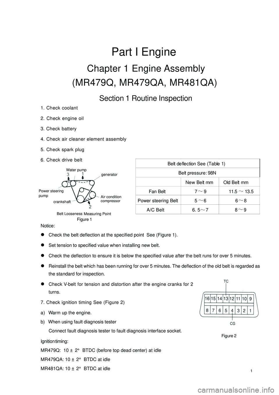
6. Check drive belt
Figure 1
Notice:
�zCheck the belt deflection at the specified point See (Figure 1).
�zSet tension to specified value when installing new belt.
�zCheck the deflection to ensure it is below the specified value after the belt runs for over 5 minutes.
�zReinstall the belt which has been running for over 5 minutes. The deflection of the old belt is regarded as
the standard for inspection.
�zCheck V-belt for tension and distortion after the engine cranks for 2
turns.
7. Check ignition timing See (Figure 2)
a) Warm up the engine.
b) When using fault diagnosis tester
Connect fault diagnosis tester to fault diagnosis interface socket.
Ignition timing:
MR479Q: 10 ± 2° BTDC (before top dead center) at idle
MR479QA: 10 ± 2° BTDC at idle
MR481QA: 10 ± 2° BTDC at idleFigure 2New Belt mm Old Belt mm
Fan Belt 7~
13. 5
Power steering Belt 5~
66~
8
A/C Belt 6. 5
~78~
9 Belt deflection See (Table 1)
Be lt pre ssure : 98NBelt Looseness
Measuring PointWater pump
Power steering
crankshaftgenerator
Air condition
compressor pump11.5~
9
Page 9 of 392
2c) When fault diagnosis tester is not used
(1) Shorting fault diagnosis interface socket 13 (TC) terminal and 4(CG) terminal.
Notice:
�zEnsure correct connection, otherwise the engine will be damaged.
�zSwitch off all electrical appliance system.
�zCheck when disconnecting cooling fan motor.
(2) Using timing light to check ignition timing.
Ignition timing: 10 ± 2° BTDC at idle
Notice:
(1) Transmission shift lever should be in neutral position when checking ignition timing.
(2) Running engine at 1,000-1,300rpm for 5s and check at idle.
(3) Remove the tester on fault diagnosis socket.
(4) Ignition timing advance angle becomes larger when the engine roate speed is higher.
(5) Remove timing light.
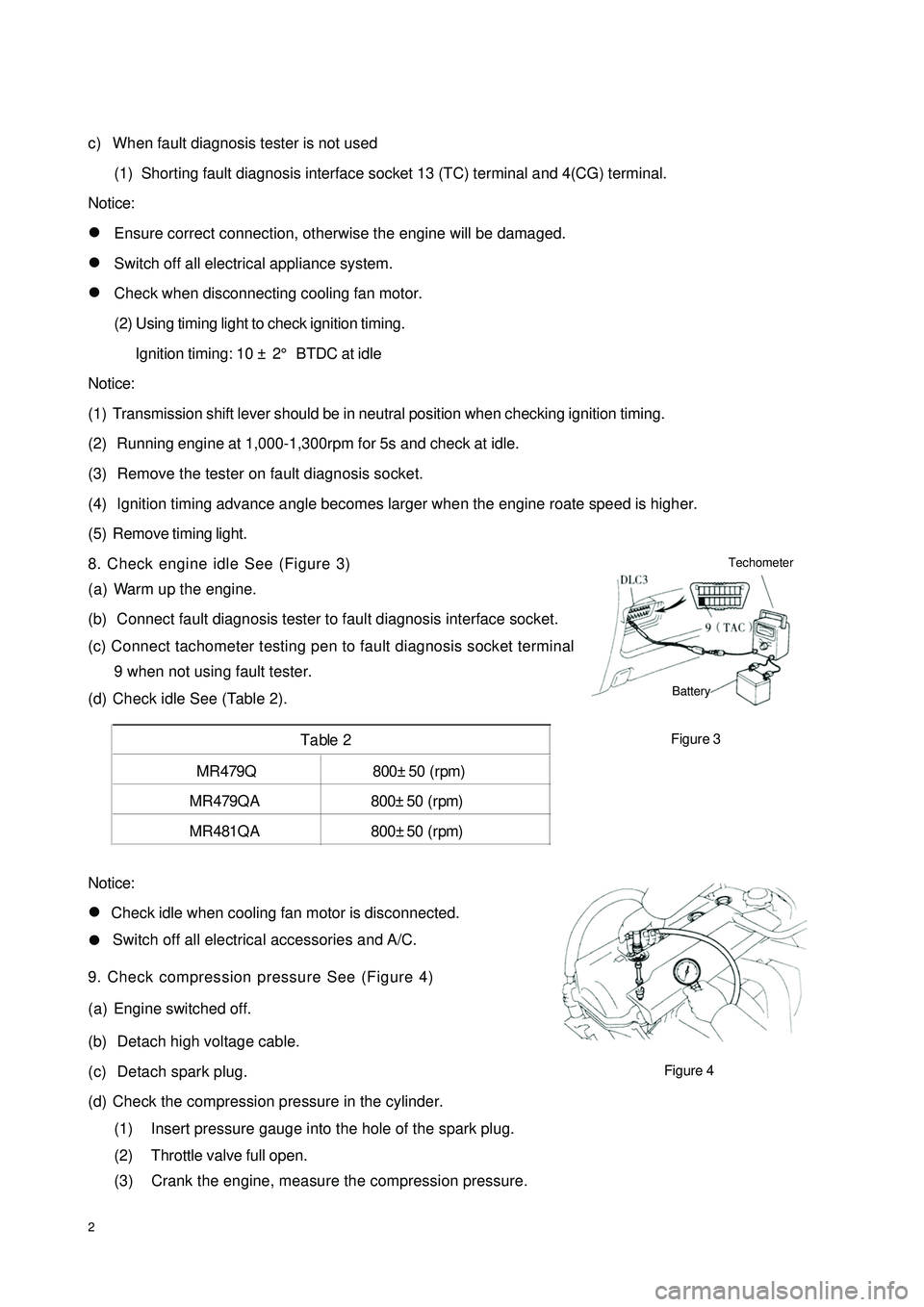
8. Check engine idle See (Figure 3)
Notice:
�zCheck idle when cooling fan motor is disconnected.
�zSwitch off all electrical accessories and A/C.
9. Check compression pressure See (Figure 4)
(a) Engine switched off.
(b) Detach high voltage cable.
(c) Detach spark plug.
(d) Check the compression pressure in the cylinder.
(1) Insert pressure gauge into the hole of the spark plug.
(2) Throttle valve full open.
(3) Crank the engine, measure the compression pressure. MR479Q 800±50 (rpm)
MR479Q A 800±50 (rpm)
MR481Q A 800±50 (rpm)Table 2(a) Warm up the engine.
(b) Connect fault diagnosis tester to fault diagnosis interface socket.
(c) Connect tachometer testing pen to fault diagnosis socket terminal
9 when not using fault tester.
(d) Check idle See (Table 2).
Figure 4Figure 3Techometer
Battery
Page 10 of 392
3The Min. compression pressure: 980 kPa
The tolerance range of the cylinders pressure: 100 kPa
Notice:
�zEnsure sufficient battery power and the engine speed is no less than 250 RPM (revolutions per minute).�zCheck the compression pressure of other cylinders in the same way.
�zComplete the measure as quick as possible.
(4) If the compression pressure in several cylinder is too low, fill some engine oil to the cylinder via the
hole of the spark plug. Check by repeating step 1-3.
Hint:
�zIf the compression pressure is improved after filling oil, the piston ring or the cylinder may be abrased
or damaged.
�zIf the pressure is still too low, the valve is stagnation or poor seal, or there is a leakage in gasket.
10. Check CO/HC
(a) Start engine.
(b) Running engine at 2500rpm for approximately 3 minutes.
(c) Insert CO/HC meter testing probe into tailpipe at least 40cm during idling.
(d) Check CO/HC concentration at idle and 2500rpm.
Hint:
�zComplete measurement within 3 minutes.
�zTest the CO/HC emission concentration at idle and 2500 rpm on QC/T630-1999 standard.
(e) Take the following steps to diagnose the fault if the CO/HC concentration does not comply with standard .
(1) Check the oxygen sensor operation.
(2) See (Table 3) for the possible cause and check and repair.
Page 12 of 392

5Section 2 Drive Belt Replacement1. Disconnect all engine pipe hose and wire joint. Remove engine assembly from the engine
compartment, jack up the body, take out the engine assembly slowly (See Provision 20, Section
Two, Chapter Two for detailed information)
2. Remove generator V-belt See (Figure 5)
3. Remove No. 1 V-belt A/C compressor to crankshaft pulley
4. Remove water pump belt See (Figure 6)
5. Install water pump V-belt
6. Adjust V-belt of steering assisting pump
(a) Adjust power steering belt tension, tighten bolt B.
(b) Tighten bolt A.
Torque : 39N. m
7. Install V-belt A/C compressor No. 1 to crankshaft pulley
8. Adjust V-belt A/C compressor No. 1 to crankshaft pulley
(a) Adjust A/C belt tension by tightening bolt B.
(b) Tighten nut A.
Torque : 39N. m
9. Install Generator V-belt See (Figure 7)
10. Adjust Generator V-belt.
Tighten bolt A and then bolt B.
Torque: Bolt A 18N. m Bolt B 58N. m
11. Check driving belt for distortion and tension
Figure 7 Figure 6 Figure 5
Page 16 of 392

9(4) Alternatively press valve tappet with the special tool (A) (B). Check
valve clearance. See (Figure 19).
8. Install cylinder head sub-assembly
(a) Remove all old gasket material.
(b) Apply the seal glue to the cylinder head.
(c) Connect wire harness and clip.
(d) Install gasket under of cylinder head.
(e) Install the cylinder head cover with 4 seal gaskets and 4 screw caps.
Torque: 7.8N. m
(f) Install 2 ventilation hoses to cylinder head cover.
(g) Connect generator wire joint.
(h) Connect generator wires.
(i) Connect oil pressure switch connector.
(j) Install wire clip.
(k) Connect A/C compressor switch connector.
9. Install electronic ignition coil and high voltage cable
10. Check engine oil for leakage
Figure 19
Page 23 of 392
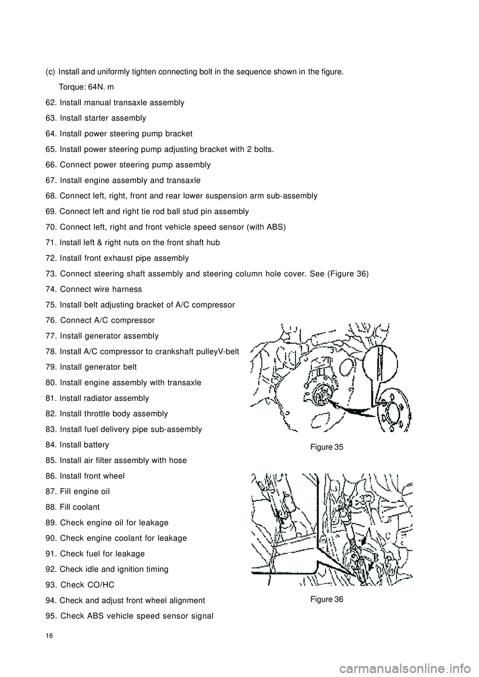
16(c) Install and uniformly tighten connecting bolt in the sequence shown inthe figure.
Torque: 64N. m
62. Install manual transaxle assembly
63. Install starter assembly
64. Install power steering pump bracket
65. Install power steering pump adjusting bracket with 2 bolts.
66. Connect power steering pump assembly
67. Install engine assembly and transaxle
68. Connect left, right, front and rear lower suspension arm sub-assembly
69. Connect left and right tie rod ball stud pin assembly
70. Connect left, right and front vehicle speed sensor (with ABS)
71. Install left & right nuts on the front shaft hub
72. Install front exhaust pipe assembly
73. Connect steering shaft assembly and steering column hole cover. See (Figure 36)
74. Connect wire harness
75. Install belt adjusting bracket of A/C compressor
76. Connect A/C compressor
77. Install generator assembly
78. Install A/C compressor to crankshaft pulleyV-belt
79. Install generator belt
80. Install engine assembly with transaxle
81. Install radiator assembly
82. Install throttle body assembly
83. Install fuel delivery pipe sub-assembly
84. Install battery
85. Install air filter assembly with hose
86. Install front wheel
87. Fill engine oil
88. Fill coolant
89. Check engine oil for leakage
90. Check engine coolant for leakage
91. Check fuel for leakage
92. Check idle and ignition timing
93. Check CO/HC
94. Check and adjust front wheel alignment
95. Check ABS vehicle speed sensor signalFigure 35
Figure 36
Page 25 of 392

181. Disconnect engine from all the wire harnesses and cables connected to body.
2. Remove air filter assembly with hose. See (Figure 38)
3. Disconnect oil pipe and water hoses
4. Loose positive and negative cables on battery
5. Detach propeller shaft
6. Loose engine left & right rear brackets after hoisting engine
7. Disconnect all the connectors of engine and the body
8. Remove engine per "Provision 20, Section 2, Chapter 2"
9. Remove A/C compressor to crankshaft pulley V-belt
10. Remove power steering pump V-belt
11. Remove water pump fan pulley
12. Remove high pressure cable.
13. Remove cylinder head cover sub-assembly
14. Remove generator assembly. See (Figure 39)
15. Put the piston in Cylinder 1 to TDC compression position
(a)Turn crankshaft pulley to align its notch to the timing mark "0"
on the timing belt cover. See (Figure 40).
(b) Check if the "K" mark on camshaft timing pulley and the timing mark
on the bearing cap are aligned. Crank the crankshaft for 360 degrees
if not. See (Figure 41).
16. Remove crankshaft pulley
17. Remove timing belt cover
18. Remove crankshaft gear or pulley cover sub-assembly
19. Remove timing belt cover sub-assembly
Figure 40 Figure 39 Figure 38
Figure 41