clock GEELY CK 2008 Workshop Manual
[x] Cancel search | Manufacturer: GEELY, Model Year: 2008, Model line: CK, Model: GEELY CK 2008Pages: 392, PDF Size: 38.86 MB
Page 26 of 392

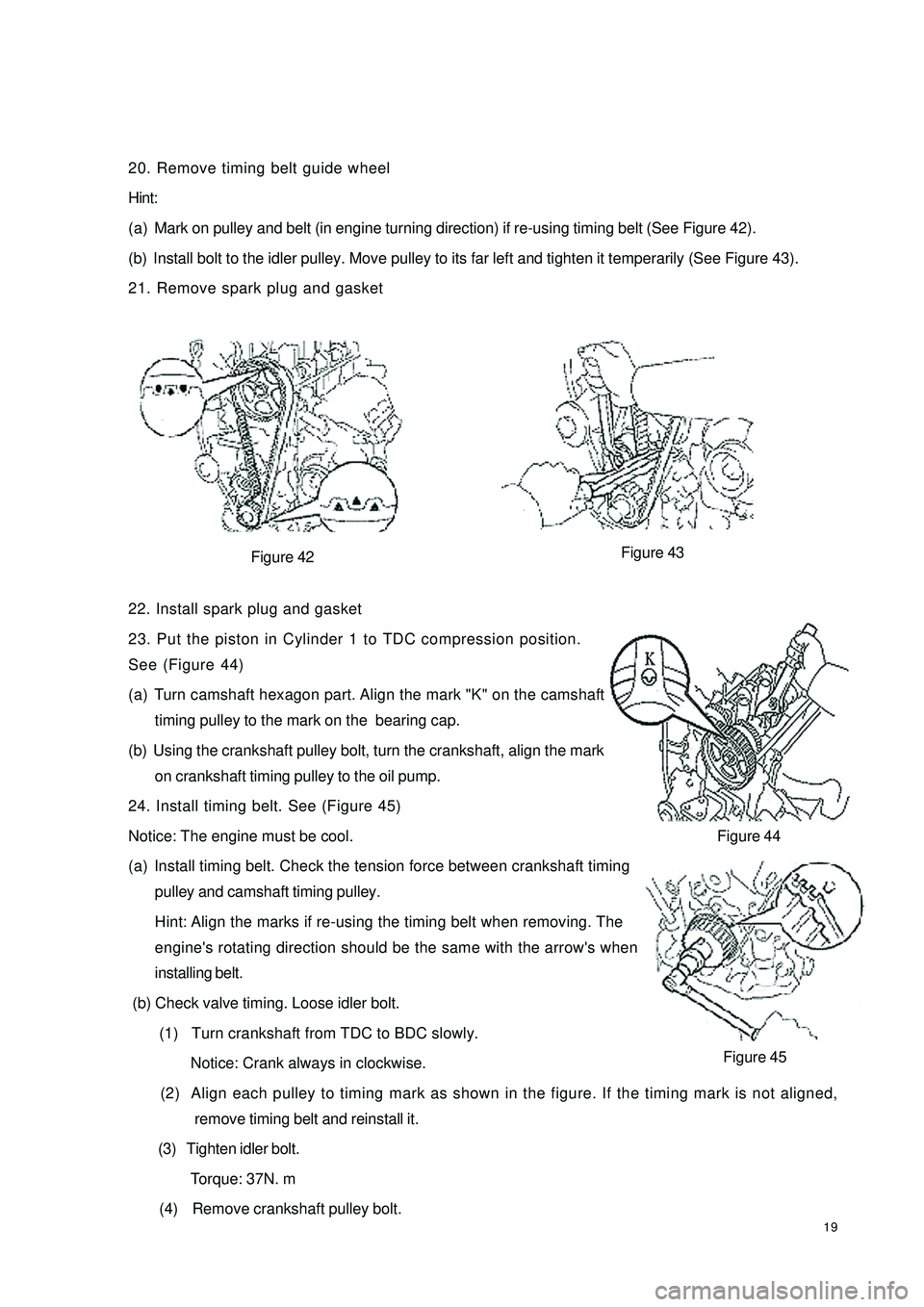
1920. Remove timing belt guide wheel
Hint:
(a) Mark on pulley and belt (in engine turning direction) if re-using timing belt (See Figure 42).
(b) Install bolt to the idler pulley. Move pulley to its far left and tighten it temperarily (See Figure 43).
21. Remove spark plug and gasket
Figure 42
22. Install spark plug and gasket
23. Put the piston in Cylinder 1 to TDC compression position.
See (Figure 44)
(a) Turn camshaft hexagon part. Align the mark "K" on the camshaft
timing pulley to the mark on the bearing cap.
(b) Using the crankshaft pulley bolt, turn the crankshaft, align the mark
on crankshaft timing pulley to the oil pump.
24. Install timing belt. See (Figure 45)
Notice: The engine must be cool.
(a) Install timing belt. Check the tension force between crankshaft timing
pulley and camshaft timing pulley.
Hint: Align the marks if re-using the timing belt when removing. The
engine's rotating direction should be the same with the arrow's when
installing belt.
(b) Check valve timing. Loose idler bolt.
(1) Turn crankshaft from TDC to BDC slowly.
Notice: Crank always in clockwise.
(2) Align each pulley to timing mark as shown in the figure. If the timing mark is not aligned,
remove timing belt and reinstall it.
(3) Tighten idler bolt.
Torque: 37N. m
(4) Remove crankshaft pulley bolt.Figure 44
Figure 45 Figure 43
Page 32 of 392

25 (b) Remove the counter gear of the camshaft.
(1) Clamp the camshaft's hexagon on the vise.
(2) Turn the counter gear cloclwise, Remove the service bolt.
(3) Remove the snap ring with a circlip pliers. See (Figure 57).
(4) Remove waved gasket, camshaft counter gear and the camshaft gear spring. See (Figure 58)
24. Remove and install spark plug hole gasket. See Provision 15 and 16, Section 3 Timing Belt
Replacement for detailed information. See (Figure 44, 45).
Figure 57
25. Install camshaft
(a) Install exhaust camshaft and turn camshaft counterclockwise to make the dowel pin cross the vertical
line a little. See (Figure 59).
(b) Apply grease to a new oil seal lip and install it into the oil seal. See (Figure 60).
Figure 59
(c) Install camshaft counter gear.
(1) Clamp the camshaft's hexagon head with a vise.
(2) Install camshaft gear spring, camshaft counter gear and waved washer. (Figure 61).
Hint: Align the pin on the gear to the spring end of the counter gear.
(3) Install the snap ring with a circlip plier.
(4) Turn the counter gear clockwise with the special tool. Align the
holes on the camshaft drive gear. Install the service bolt.Figrue 61Rotate
Figure 58
Figure 60
Page 33 of 392

26(d) Install intake camshaft.
(1) Make the exhaust camshaft dowel pin a bit higher than the top of the cylinder head.
(2) Apply grease to camshaft's contact surface.
(3) Install intake camshaft gear to exhaust camshaft gear ,
Align the matchmarks on each gear. See (Figure 62).
(4) Check the timing marks on the camshaft gear for
alignment.See (Figure 63).
Hint: Matchmark is on the top.
26. Adjust valve clearance
27. Install camshaft timing pulley
Turn the camshaft's hexagon head. Tighten the timing pulley bolt. See (Figure 64).
Torque: 59N. M
Figure 63
Figure 65
28. Install the timing belt
(a) Align the marks on timing belt and the one on camshaft timing pulley.
(b) Install timing belt. Check tension force between the crankshaft timing pulleys. See (Figure 65).
29. Check valve timing
(a) Loose idler bolt.
(b) Turn crankshaft from TDC clockwise for 2 cycles.
(c) Check and align each pully to the timing mark as shown in Figure 66. Remove timing belt and reinstall it
if not.
30. Install crankshaft gear or pulley cover sub-assembly
Torque: 9.3N. mFigure 62 Install Mark
Timing MarkInstall Mark
Install Mark
Timing Mark
5-6mm Figure 64
Figure 66
Page 90 of 392

83ECU microcomputer consists of microprocessor, memory, clock generator, timer, I/O interface and input
level A/D converter that are integrated in a large scale integrated circuit chip, that is SCM (Single Chip
Microcomputer).
1. Input level
The input signals from the sensor are pre-processed by the input level. The input signals are sent to protected
circuit first, sometimes through the signal converter and amplifier, and then sent to microcomputer.
The sensor signal is separated into switch type and analog type. Ignition on/off signal, camshaft position
signal, vehicle speed signal and A/C signal are switch type; Signals such as battery voltage, engine temperature,
intake temperature, airflow, intake manifold absolute pressure, throttle opening, excessive air coefficient,
knock, A/C refrigerant pressure are analog type. Analogy signal can only be processed by the digital micro-
computer after being converted into digital signal by A/D converter. Hence, data collection shall be made
first for analog signal, and the sampling shall be maintained also.
Speed and crankshaft position reference signal from the sensor is processed in a dedicated circuit to restrain
the interference pulse.
2. Microcomputer
The microcomputer of the engine electronic control unit is integrated in a single chip microcomputer, consist-
ing of the following:
(1) Microprocessor, microprocessor is also called as central processing unit (CPU), consisting of the following
three parts:
Arithmetic logic unit.
Register group.
Controller.
(2) System assembly, The data transferred among the internal sections of the single chip microcomputer
(SCM) is performed on the internal bus, while that between the SCM and other components is performed
on the external bus. The external bus is also called system bus. It is separated into data bus, address bus
and control bus.
(3) Memory, the memory is designed to store the binary data. The primary components of the memory are:
Memory.
Data register.
Address register, address decoder.
a. Memory controller
(4) A/D converter
(5) I/O interface.
(6) Clock generator.
(7) Timer
(8) CAPCOM unit.
(9) Watchdog timer.
(10) Interrupt system.
Page 93 of 392

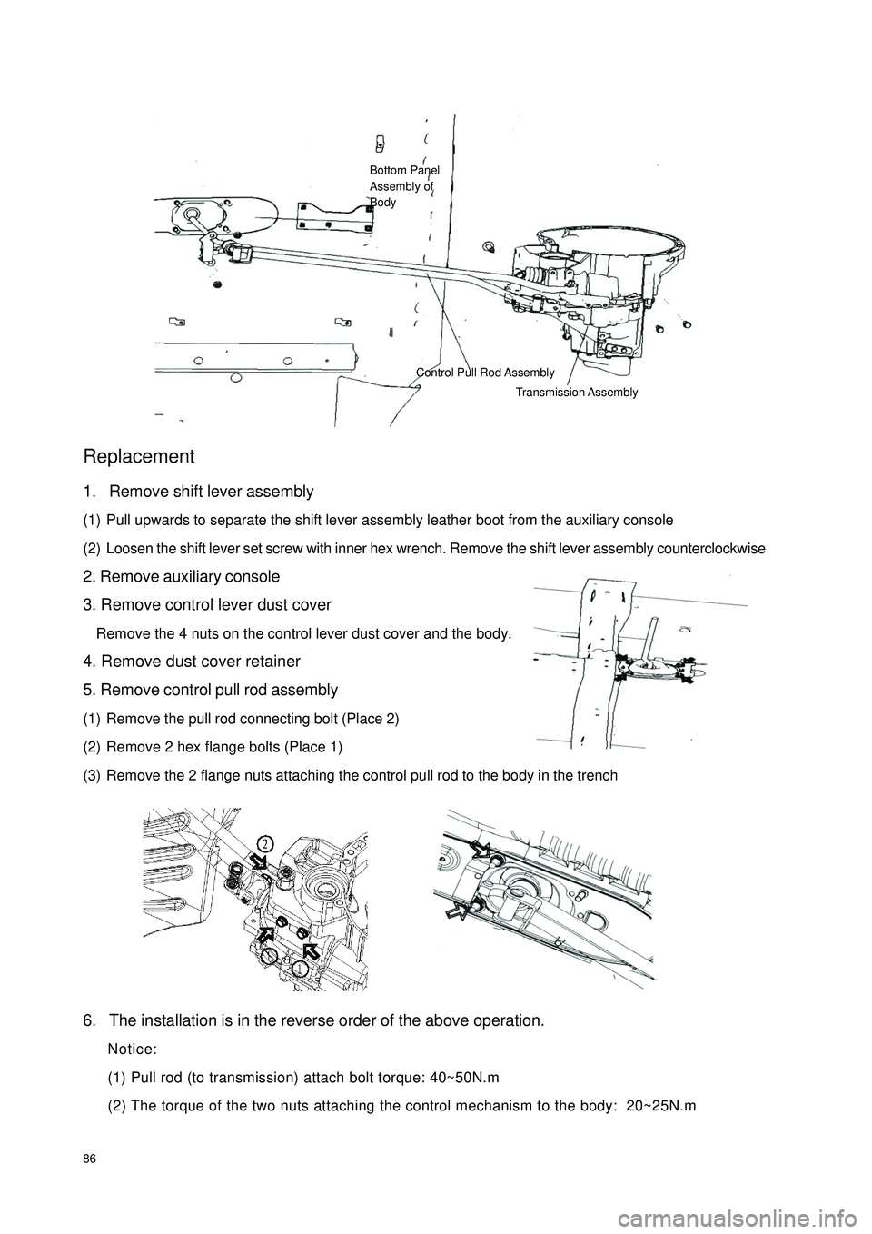
86Replacement1. Remove shift lever assembly
(1) Pull upwards to separate the shift lever assembly leather boot from the auxiliary console
(2) Loosen the shift lever set screw with inner hex wrench. Remove the shift lever assembly counterclockwise
2. Remove auxiliary console
3. Remove control lever dust cover
Remove the 4 nuts on the control lever dust cover and the body.
4. Remove dust cover retainer
5. Remove control pull rod assembly
(1) Remove the pull rod connecting bolt (Place 2)
(2) Remove 2 hex flange bolts (Place 1)
(3) Remove the 2 flange nuts attaching the control pull rod to the body in the trench
6. The installation is in the reverse order of the above operation.
Notice:
(1) Pull rod (to transmission) attach bolt torque: 40~50N.m
(2) The torque of the two nuts attaching the control mechanism to the body: 20~25N.mBottom Panel
Assembly of
BodyControl Pull Rod Assembly
Transmission Assembly
Page 95 of 392

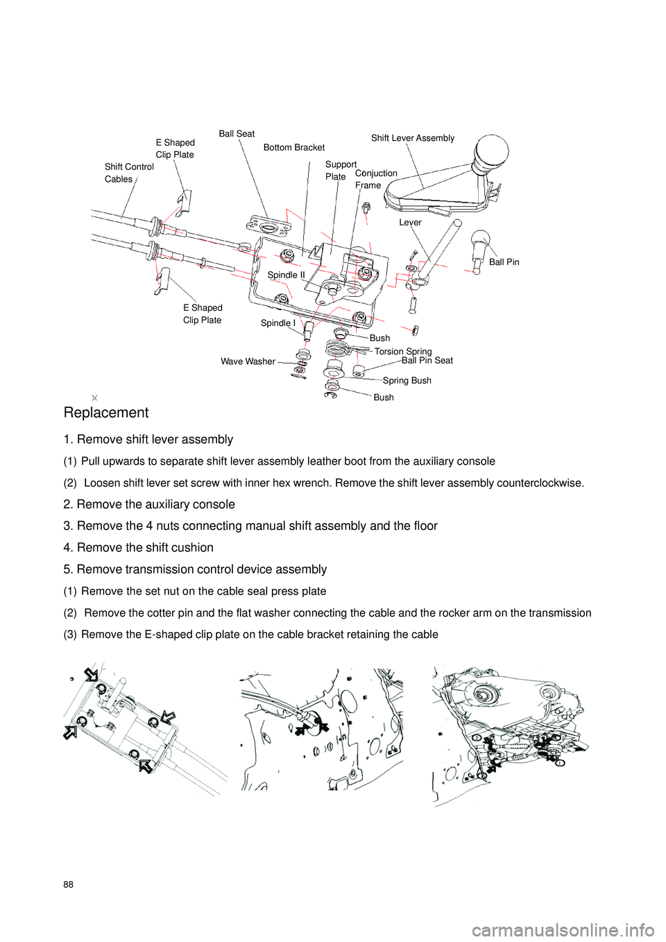
88Replacement1. Remove shift lever assembly
(1) Pull upwards to separate shift lever assembly leather boot from the auxiliary console
(2) Loosen shift lever set screw with inner hex wrench. Remove the shift lever assembly counterclockwise.
2. Remove the auxiliary console
3. Remove the 4 nuts connecting manual shift assembly and the floor
4. Remove the shift cushion
5. Remove transmission control device assembly
(1) Remove the set nut on the cable seal press plate
(2) Remove the cotter pin and the flat washer connecting the cable and the rocker arm on the transmission
(3) Remove the E-shaped clip plate on the cable bracket retaining the cableShift Control
CablesE Shaped
Clip PlateBall SeatShift Lever Assembly LeverBall PinSpindle IISpindle IE Shaped
Clip PlateWave WasherBushBushSpring BushBall Pin Seat Torsion Spring Support
Plate Bottom BracketConjuction
Frame
Page 219 of 392

212II.INSTALLATION1. Install the electrical connector of the headlamp assembly.
2. Install the headlamp assembly and the 3 mounting bolts.
3. Install the front bumper.
4. Adjust the condition of the vehicle.
5. Adjust the headlamp beam.III.HEADLAMP BULB REPLACEMENT1 - LOW BEAM DUST COVER 2 - HIGH BEAM DUST COVER 3 - TURN SIGNAL LAMP DUST
COVER 4 - HEADLAMP HOLDER
1. Replace the high and low beam bulbs
�y Turn and remove the dust cover counter-clockwise
�y Pull out the bulb plug
�y Press and release the wire clip
�y Pull out the lamp-holder, and remove the bulb
�y Replace the bulb
2. Replace the turn signal lamp bulbs
�y Remove the 3 screws on the dust cover with screwdriver
�yTurn the lamp-holder counter-clockwise. Pull out the lamp-holder, and remove the bulb
�yReplace the bulb
3. Replace the headlamp bulbs
�yTurn the lamp-holder counter-clockwise. Pull out the lamp-holder, remove the bulb, and replace the
bulb.1 2 3 4
Page 222 of 392

215Section 4 Front Fog Lamp ReplacementI. REMOVAL1. Remove the front bumper.(See bumper replacement)
2. Remove the electrical connector.
3. Remove the mounting bolts (A, B as shown in the illustration).
4. Remove the front fog lamp assembly.II. INSTALLATION1. Install the front fog lamp assembly.
2. Install the mounting bolts.
3. Install the electrical connector.
4. Install the front bumper.
5. Adjust the condition of the vehicle.
6. Adjust the front fog lamp beam.III. FRONT FOG LAMP BULB REPLACEMENT1. Press and Turn counter-clockwise, then remove the dust cover
2. Pull out the bulb
3. Replace the bulbABElectrical
Connection
Page 223 of 392

216IV. FRONT FOG LAMP BEAM ADJUSTMENT1. Adjust the tire inflation pressure with the standard value
2. Start the engine
3. Turn the fog lamp switch ON
4. Adjust the fog lamp beam.
Turn the bolt A for adjusting fog lamp beam in vertical direction.
NOTES:
Turn the screwdriver counter-clockwise to make the light beam up, clockwise make the light beam down.
Page 225 of 392

218II. INSTALLATION1. Install the rear combination lamp and then the 3 mounting bolts.
2. Install the electrical connector.
3. Install the rear trunk interior trim.
4. Install the seal strip.III. REAR COMBINATION LAMP BULB REPLACEMENT1. Remove the O-ring seal.
2. Turn the lamp-holder counter-clockwise. Pull out the lamp-holder.
3. Remove the bulb and replace the bulb.Section 6 High Mounted Stop Lamp Replacement�zRemove the High mounted stop lamp in direction 1 and 2. (as shown above in the illustration)
�zDisconnect the connector.Partition
High Mounted
Stop Lamp