fog light GEELY CK 2008 Workshop Manual
[x] Cancel search | Manufacturer: GEELY, Model Year: 2008, Model line: CK, Model: GEELY CK 2008Pages: 392, PDF Size: 38.86 MB
Page 5 of 392

Section 8 Parking Brake System..................................................................................... 155........................................................157Chapter 1 Survey................................................................................................157
Chapter 2 Starting and Charging System.........................................................161Section 1 Starting System (MR479Q MR479QA MR481QA)..........................................161
Section 2 Charging System (MR479Q, MR479QA, MR481QA).......................................164Chapter 3 Combination Meter System..............................................................171Section 1 Circuit Diagram of Combination Meter and Location of Multi-pin Plug-in
Terminal............................................................................................................................ 171
Section 2 Malfunction Symptom Table and Solution Procedure...........................................174
Section 3 Combination Meter.......................................................................................... 187Chapter 4 Wiper and Washer System...............................................................193Section 1 Wiper and Washer System Inspection............................................................ 193
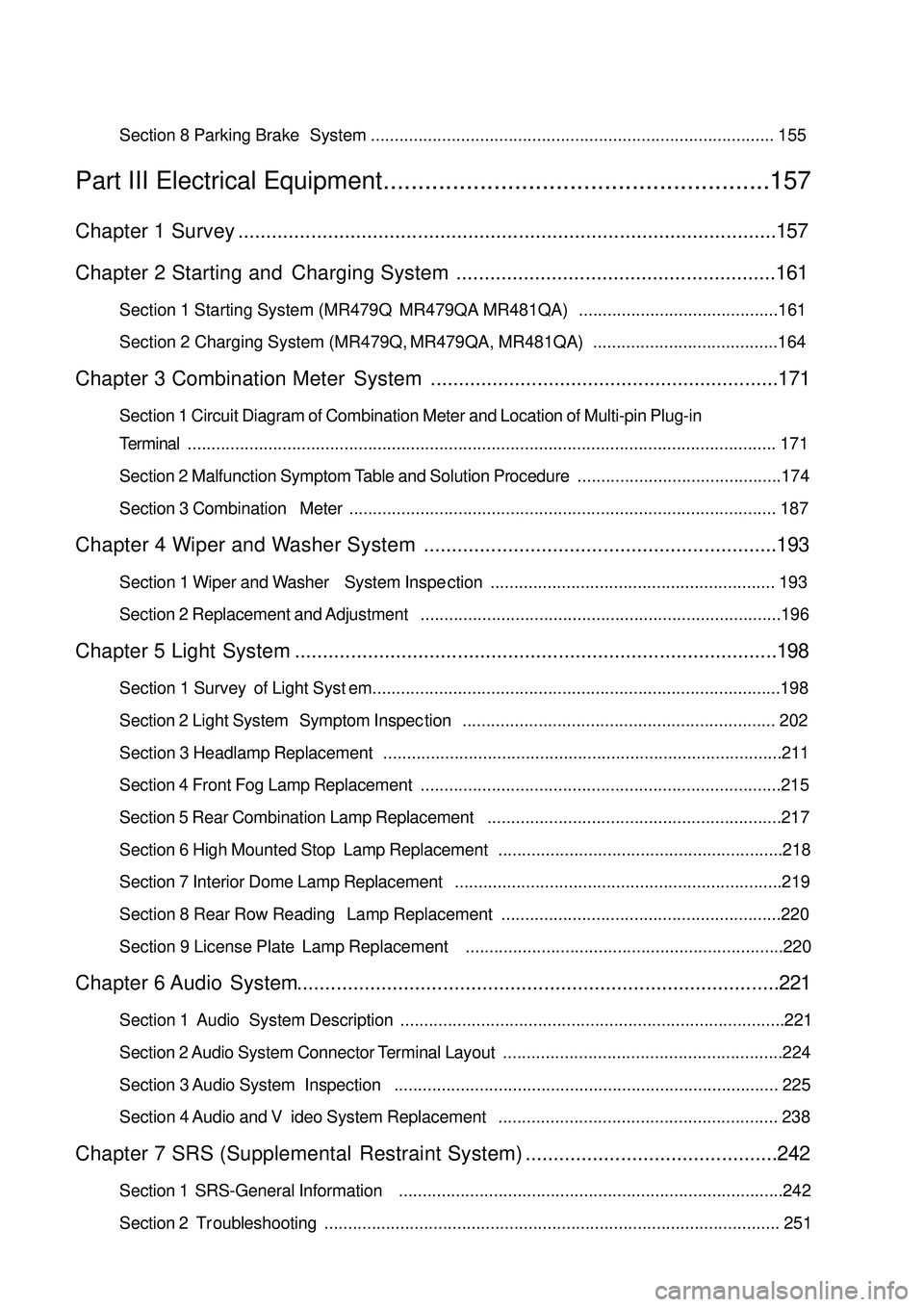
Section 2 Replacement and Adjustment............................................................................196Chapter 5 Light System......................................................................................198Section 1 Survey of Light System......................................................................................198
Section 2 Light System Symptom Inspection.................................................................. 202
Section 3 Headlamp Replacement....................................................................................211
Section 4 Front Fog Lamp Replacement............................................................................215
Section 5 Rear Combination Lamp Replacement..............................................................217
Section 6 High Mounted Stop Lamp Replacement............................................................218
Section 7 Interior Dome Lamp Replacement.....................................................................219
Section 8 Rear Row Reading Lamp Replacement...........................................................220
Section 9 License Plate Lamp Replacement...................................................................220Chapter 6 Audio System......................................................................................221Section 1 Audio System Description.................................................................................221
Section 2 Audio System Connector Terminal Layout...........................................................224
Section 3 Audio System Inspection................................................................................. 225
Section 4 Audio and Video System Replacement........................................................... 238Chapter 7 SRS (Supplemental Restraint System).............................................242Section 1 SRS-General Information.................................................................................242
Section 2 Troubleshooting................................................................................................ 251Part III Electrical Equipment
Page 178 of 392

171Chapter 3 Combination Meter SystemSection 1 Circuit Diagram of Combination Meter and Location of
Multi-pin Plug-in TerminalI. CIRCUIT DIAGRAM OF CONBINATION METERSpeed Signal
Ground The Sensor
Revolution SignalWater Temperature SignaFuel Level GaugeTachometer
SpeedometerWater
Temperature Gauge
Feul Level Gauge
OdometerHigh Beam Lamp
Rear Defrost Lamp
Rear Defog Lamp
Backlight
Water Temperature WarningPower Steering
Fuel WarningCharge
Brake Fluid
Oil Pressure
Engine Malfunction
Driver's seat belt
Park Brake
SRS(main)
SRS(sub)
Page 195 of 392

188Symptom Suspe cte d Area
1. Ha rne ss or connec tor.
2. ABS controlle r or ABS wa rning light driver module
3. C ombina tion me te r a s s e mbly
1. Ha rne ss or connec tor.
2. SRS controller
3. C ombina tion me te r a s s e mbly
1. Ha rne ss or connec tor.
2. SRS controller
3. C ombina tion me te r a s s e mbly
1. Ha rne ss or connec tor.
2. O il pr e s s ur e s w it c h a s s e mbly
3. C ombina tion me te r a s s e mbly
1. Ha rne ss or connec tor.
2. Headlamp light control switch
3. C ombina tion me te r a s s e mbly
1. Ha rne ss or connec tor.
2. Headlamp light control switch
3. C ombina tion me te r a s s e mbly
1. Ha rne ss or connec tor.
2. Ce ntra l c ontrolle r or re a r de fros t sw itc h
3. C ombina tion me te r a s s e mbly
1. Ha rne ss or connec tor.
2. Electric Power Steering controller
3. C ombina tion me te r a s s e mbly
1. Ha rne ss or connec tor.
2. Engine c oola nt te mpe ra ture se nsor
3. C ombina tion me te r a s s e mbly
1. Ha rne ss or connec tor.
2. Se a t belt buckle switch
3. C ombina tion me te r a s s e mbly ABS warning light doe s not light up
SRS wa rning light doe s not light up
SRS (Sub) indic a tor doe s not light up
Oil pre ssure wa rning light does not light
up
Water temperature warning indicator
doe s not light up
Se at be lt wa rning indic a tor doe s not light
up High be a m indica tor does not light up
Re a r fog indica tor does not light up
Re a r defrost indic a tor doe s not light up
EP S wa rning indic ator doe s not light up
Page 199 of 392

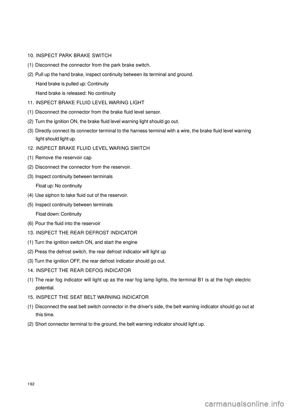
19210. INSPECT PARK BRAKE SWITCH
(1) Disconnect the connector from the park brake switch.
(2) Pull up the hand brake, inspect continuity between its terminal and ground.
Hand brake is pulled up: Continuity
Hand brake is released: No continuity
11. INSPECT BRAKE FLUID LEVEL WARING LIGHT
(1) Disconnect the connector from the brake fluid level sensor.
(2) Turn the ignition ON, the brake fluid level warning light should go out.
(3) Directly connect its connector terminal to the harness terminal with a wire, the brake fluid level warning
light should light up.
12. INSPECT BRAKE FLUID LEVEL WARING SWITCH
(1) Remove the reservoir cap
(2) Disconnect the connector from the reservoir.
(3) Inspect continuity between terminals
Float up: No continuity
(4) Use siphon to take fluid out of the reservoir.
(5) Inspect continuity between terminals
Float down: Continuity
(6) Pour the fluid into the reservoir
13. INSPECT THE REAR DEFROST INDICATOR
(1) Turn the ignition switch ON, and start the engine
(2) Press the defrost switch, the rear defrost indicator will light up
(3) Turn the ignition OFF, the rear defrost indicator should go out.
14. INSPECT THE REAR DEFOG INDICATOR
(1) The rear fog indicator will light up as the rear fog lamp lights, the terminal B1 is at the high electric
potential.
15. INSPECT THE SEAT BELT WARNING INDICATOR
(1) Disconnect the seat belt switch connector in the driver's side, the belt warning indicator should go out at
this time.
(2) Short connector terminal to the ground, the belt warning indicator should light up.
Page 205 of 392

198Chapter 5 Light SystemSection 1 Survey of Light SystemI. COMPOSITION1. Front combination lamp assembly: turn signal lamp, high beam, low beam, head lamp, front position lamp.
2. Rear combination lamp: turn signal lamp, back-up lamp, rear fog lamp, tail lamp, brake lamp, retro reflector.
3. Front fog lamp
4. Side turn signal lamp
5. High mounted stop lamp
6. Rear trunk lamp
7. License plate lamp
8. Interior dome lamp
9. Rear row reading lamp
10. Door lampshield and bulb assemblyII. NOTES FOR REPAIR1. NOTES WHEN REPAIRING ELECTRICAL EQUIPMENTS
(a) Disconnect the battery ground cable.
2. Notes when replacing a headlamp bulb
(a) Before replacing a halogen bulb, turn the headlamp OFF to make it cool.
(b) When installing a new halogen bulb, do not touch the glass part of the bulb with bare hands.
(c) If there is oil stain on the surface of halogen bulb (headlamp and front fog lamp) when the lamps are
turned ON, its service life will be shortened.
(d) Halogen bulbs (headlamp and front fog lamp) have pressurized gas inside and require special handling.
They can explode if dropped to ground.The glass fragments will splash up.
(e) When replacing, make sure to use the bulbs with the same power, same model.
(f) After the bulb is installed, make the lamp holder tight.
Page 207 of 392

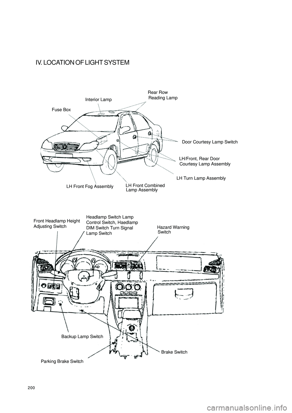
200IV. LOCATION OF LIGHT SYSTEMFuse BoxInterior LampRear Row
Reading LampLH Turn Lamp Assembly
Lamp Assembly LH Front Fog Assembly
Front Headlamp Height
Adjusting SwitchHeadlamp Switch Lamp
Control Switch, Haedlamp
DIM Switch Turn Signal
Lamp SwitchHazard Warning
SwitchParking Brake SwitchBackup Lamp Switch
Brake SwitchDoor Courtesy Lamp Switch
LH/Front, Rear Door
Courtesy Lamp Assembly
LH Front Combined
Page 210 of 392

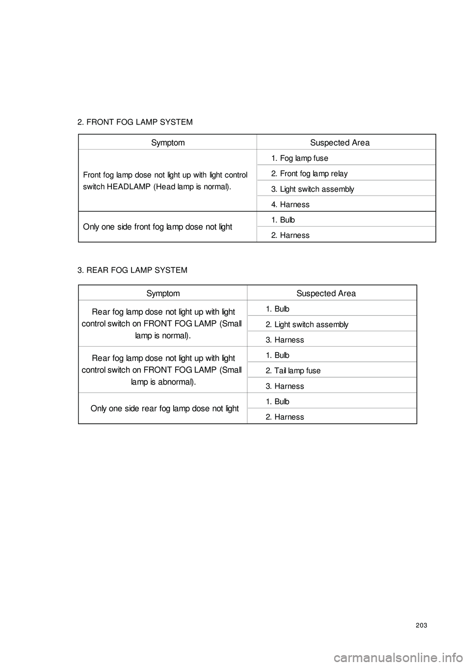
2032. FRONT FOG LAMP SYSTEM
3. REAR FOG LAMP SYSTEMSymptom Suspected Area
1. Fog la mp fuse
2. Front fog la mp rela y
3. Light switc h a ssembly
4. Harne ss
1. Bulb
2. Harne ss Front fog lamp dose not light up with light c ontrol
switch HEADLAMP (Head lamp is normal).
Only one side front fog la mp dose not lightSymptom Suspected Area
1. Bulb
2. Light switc h a ssembly
3. Harne ss
1. Bulb
2. T a il la mp f us e
3. Harne ss
1. Bulb
2. Harne ss Re a r fog lamp dose not light up with light
control switch on FRONT FOG LAMP (Small
la mp is nor ma l) .
Re a r fog lamp dose not light up with light
control switch on FRONT FOG LAMP (Small
la mp is abnormal).
Only one side rea r fog la mp dose not light
Page 213 of 392

2069. LICENSE PLATE LAMP
10. REAR TRUNK LAMPII. LIGHT SYSTEM FAULTS INSPECTION1. HEADLAMP COMBINATION SWITCH ASSEMBLYSymptom Suspec te d Area
1. Bulb
2. H a rne ss Lic ense plate la mp does not light (Ta il la mp is
norma l) Headlamp Combination Switch Range IllustrationTurn
SwitchLeft Turn
Straight Run
Right TurnLamp
Switch Horn
High Beam
Dipped BeamLamp HandleFog Light Handle
Front Fog Lamp
Front Fog Lamp
Front Fog LampFront And Rear
Fog Lamp
Front And Rear
Fog LampHeadlamp
Headlamp
HeadlampPosition Lamp
Position Lamp
Position Lamp99
9
9
999
5BB1
5BB2
5BB35BB1
9NB4
9NB1 9NB5Symptom Suspec te d Area
1 .
Bulb
2 .
R e a r t r unk la mp s w it c h
3 .
Harness Re ar trunk la mp does not light (Room la mp is
norma l)
Page 223 of 392

216IV. FRONT FOG LAMP BEAM ADJUSTMENT1. Adjust the tire inflation pressure with the standard value
2. Start the engine
3. Turn the fog lamp switch ON
4. Adjust the fog lamp beam.
Turn the bolt A for adjusting fog lamp beam in vertical direction.
NOTES:
Turn the screwdriver counter-clockwise to make the light beam up, clockwise make the light beam down.