lights GEELY CK 2008 Workshop Manual
[x] Cancel search | Manufacturer: GEELY, Model Year: 2008, Model line: CK, Model: GEELY CK 2008Pages: 392, PDF Size: 38.86 MB
Page 72 of 392
65g. Ignition system failure;
h. Low engine compression pressure.
(3) Diagnosis and Troubleshooting
a. First, check the fuel tank for fuel level, turn on the ignition switch, if fuel gauge pointer does not
move or fuel level warning lamp lights, then the fuel tank is empty, fuel shall be filled at this time.
b. Check that the electrical fuel pump for operation. Remove the fuel tank, you may use a wire to
connect the two jacks of the fuel pump for short, then turn on the ignition switch. The fuel pump
operation sound shall be able to be heard from the fuel tank nozzle or fuel flow can be felt with hand
pinching the tube; or remove the return hose on the fuel pressure regulator, check that the fuel
flows out; Direct judgment can be made if it is equipped with fuel pressure gage.
If electrical fuel pump is inoperative, check whether the main fuse, main relay, fuel pump relay,
fuel pump control circuit and ECU are OK. If all of them are OK, check fuel pump circuit for open,
short or damaged check valve. Repair or replacement shall be made when problems are found.
c. If there is no injection sound in injector, check injector control circuit for fault. You may use a
testing lamp with big resistance to be connected to the injector wiring connector, turn on the ignition
switch. If the testing lamp lights up, it indicates that the injector has been damaged and shall be
replaced; if the testing lamp does not light up, check whether the main fuse, EFI relay, fuse, ignition
switch and ECU terminal are OK, repair or replace them if they are not OK.
d. If there is low fuel pressure, the injection amount would be small and the engine won't start, you
should check the fuel filter for block and fuel pump safety valve for damage and check whether the
fuel pressure regulator is within the normal range, otherwise those components shall be repaired or
replaced.
e. Electric injection engine normally spot contact start the engine.
f. Check for open in the throttle position sensor (TPS) circuit.
g. Check whether there is Diagnostic Trouble Code (DTC), if there is, check it by the DTC; if there
is not, check the high voltage spark for intensity, if it is too weak, check spark plug, high voltage
wire, high voltage coil, distributor cover for faults, if there are faults, repair or replace them.
h. Check the compression pressure in the cylinder, insert the compression pressure gauge into the
spark plug hole, completely open the throttle, measure the compression pressure while starting the
engine. If the compression pressure is less than 980kPa when engine speed is more than 250r/min,
remove and inspect the engine and troubleshoot it.
3. The engine cranks but can not start
(1) Symptom
When starting the engine, starter can crank the engine but fail to start the engine.
(2) Causes:
a. Ignition advance angle is unfavorable;
b. Ignition is out of sequence, there is misfire;
c. High voltage spark is too weak;
d. The fuel pressure is too low;
e. fuel pressure regulator leakage;
Page 140 of 392
13311. Complete the service or replace the steering column assembly, the installation procedure is in the reverseorder of the removal
Notice:
(1) after the installation of the ignition lock core, check the steering lock operation: the
steering mechanism lock when the ignition key is pulled out; the steering mechanism
unlock when the key is inserted and turned to ACC position
(2)The torque of the 2 bolts and 2 nuts securing the steer column assembly:
16~26N.m
(3) connect the wire harness into place and make sure the wiring is good
(4) After properly adjust the positions of the combination switch and the steering column
upper and lower cover, tighten the 3 screws attaching the combination switch and the
steering column
(5) Torque of the universal joint yoke and steering gear assembly locking bolt: 22~34N.m
(6) Torque of the 4 set bolts of the dust cover and press plate: 16~26N.m
(7) When installing the steering wheel assembly, align the matchmarks of the steering wheel
and steering main shaft assembly,
Torque of the steering wheel specific inner torx bolt: 40~60N.m
(7) Check the air bag, it is not allowed to use the air bag parts from another vehicle
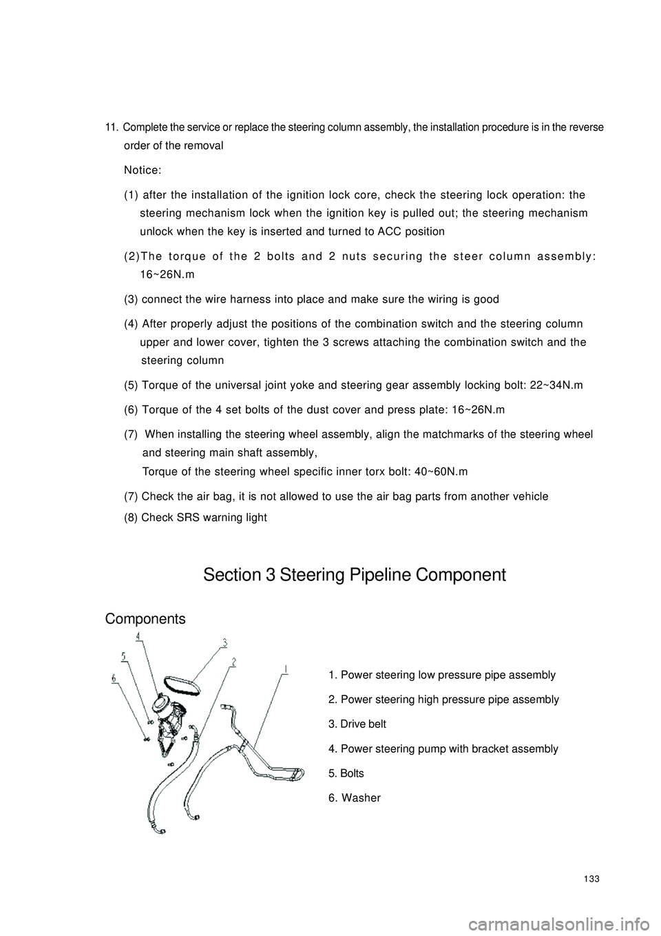
(8) Check SRS warning lightSection 3 Steering Pipeline ComponentComponents1. Power steering low pressure pipe assembly
2. Power steering high pressure pipe assembly
3. Drive belt
4. Power steering pump with bracket assembly
5. Bolts
6. Washer
Page 175 of 392
1687. INSPECT CHARGING CIRCUIT WITHOUT LOAD
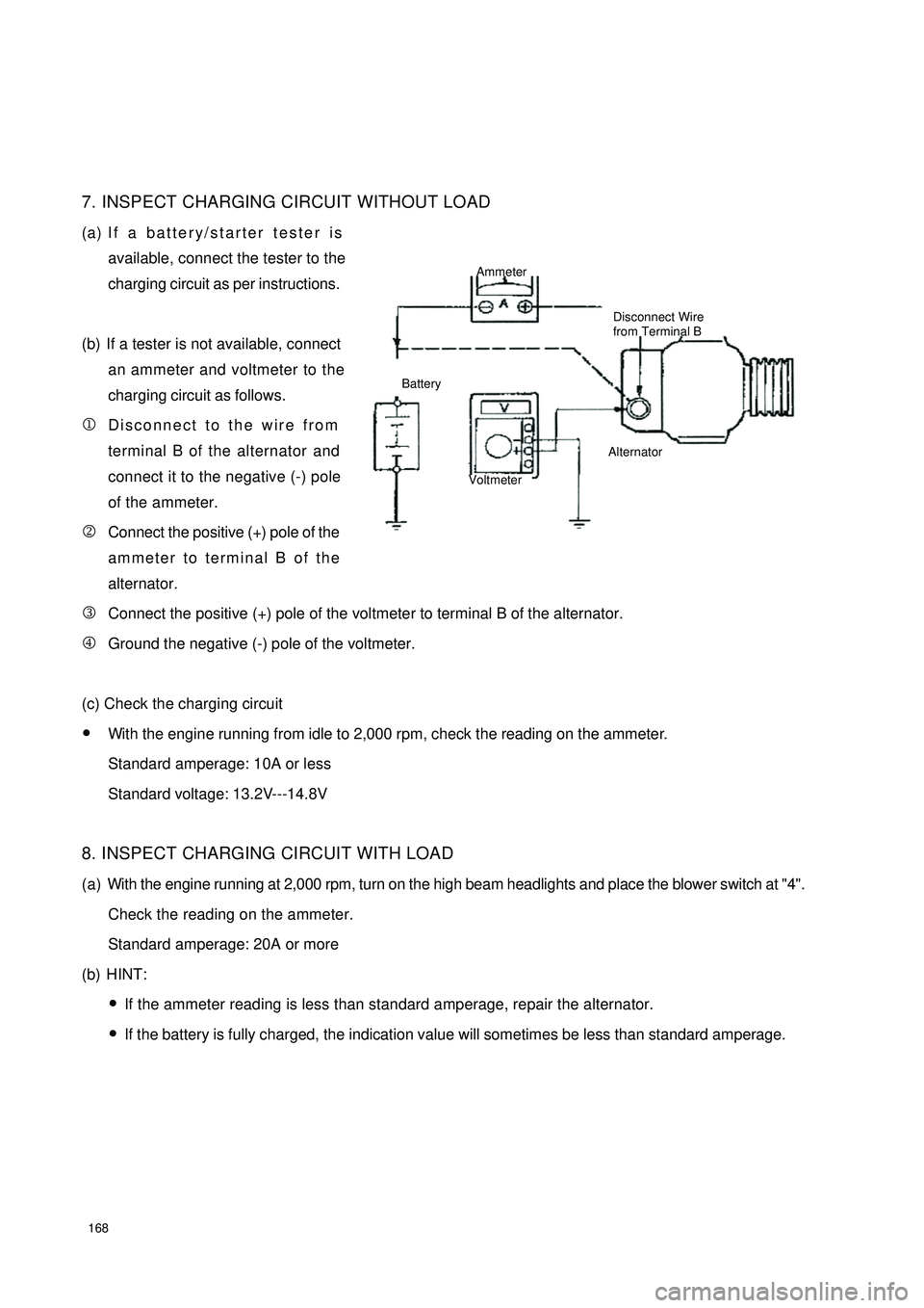
(a) If a battery/starter tester is
available, connect the tester to the
charging circuit as per instructions.
(b) If a tester is not available, connect
an ammeter and voltmeter to the
charging circuit as follows.
1Disconnect to the wire from
terminal B of the alternator and
connect it to the negative (-) pole
of the ammeter.
2Connect the positive (+) pole of the
ammeter to terminal B of the
alternator.
3Connect the positive (+) pole of the voltmeter to terminal B of the alternator.
4Ground the negative (-) pole of the voltmeter.
(c) Check the charging circuit
�yWith the engine running from idle to 2,000 rpm, check the reading on the ammeter.
Standard amperage: 10A or less
Standard voltage: 13.2V---14.8V
8. INSPECT CHARGING CIRCUIT WITH LOAD
(a) With the engine running at 2,000 rpm, turn on the high beam headlights and place the blower switch at "4".
Check the reading on the ammeter.
Standard amperage: 20A or more
(b) HINT:
�yIf the ammeter reading is less than standard amperage, repair the alternator.
�yIf the battery is fully charged, the indication value will sometimes be less than standard amperage.Ammeter
Disconnect Wire
from Terminal B
Battery
VoltmeterAlternator
Page 193 of 392
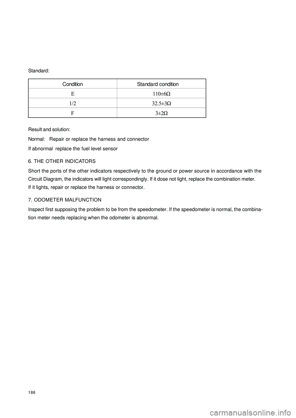
186Standard:
Result and solution:
Normal:Repair or replace the harness and connector
If abnormal replace the fuel level sensor
6. THE OTHER INDICATORS
Short the ports of the other indicators respectively to the ground or power source in accordance with the
Circuit Diagram, the indicators will light correspondingly. If it dose not light, replace the combination meter.
If it lights, repair or replace the harness or connector.
7. ODOMETER MALFUNCTION
Inspect first supposing the problem to be from the speedometer. If the speedometer is normal, the combina-
tion meter needs replacing when the odometer is abnormal.Condition Standa rd condition
E 110±6Ω
1/2 32.5±3Ω
F3±2Ω
Page 194 of 392
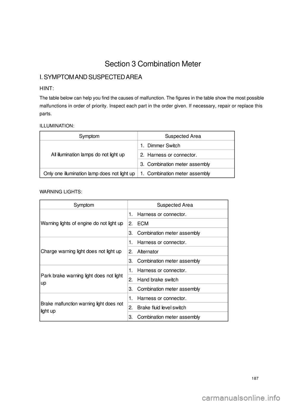
187Section 3 Combination MeterI. SYMPTOM AND SUSPECTED AREAHINT:
The table below can help you find the causes of malfunction. The figures in the table show the most possible
malfunctions in order of priority. Inspect each part in the order given. If necessary, repair or replace this
parts.
ILLUMINATION:
WARNING LIGHTS:Symptom Suspected Area
1. Dimmer Switch
2. Harness or connector.
3. Combina tion me te r a s se mbly
Only one illumina tion la mp doe s not light up 1. Combina tion me ter asse mblyA ll illumina t ion la mps do not light upSymptom Suspected Area
1. Ha rness or connec tor.
2. ECM
3. Combination me te r a sse mbly
1. Ha rness or connec tor.
2. Alterna tor
3. Combination me te r a sse mbly
1. Ha rness or connec tor.
2. Hand brake switch
3. Combination me te r a sse mbly
1. Ha rness or connec tor.
2. Bra ke fluid le ve l switc h
3. Combination me te r a sse mbly Wa rning lights of e ngine do not light up
Cha rge wa rning light doe s not light up
P a rk bra ke wa rning light does not light
upBrake malfunc tion warning light doe s notlight up
Page 199 of 392
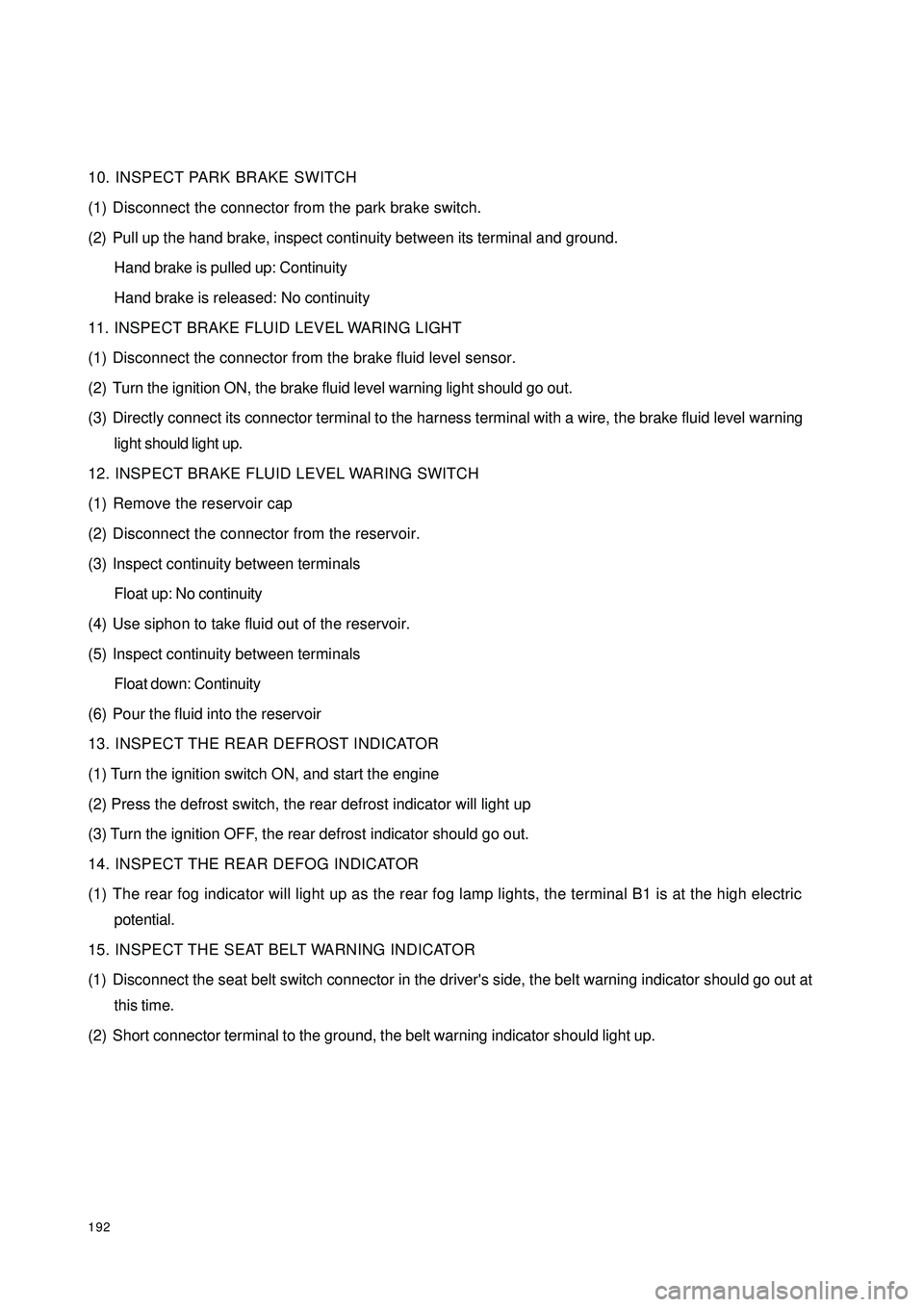
19210. INSPECT PARK BRAKE SWITCH
(1) Disconnect the connector from the park brake switch.
(2) Pull up the hand brake, inspect continuity between its terminal and ground.
Hand brake is pulled up: Continuity
Hand brake is released: No continuity
11. INSPECT BRAKE FLUID LEVEL WARING LIGHT
(1) Disconnect the connector from the brake fluid level sensor.
(2) Turn the ignition ON, the brake fluid level warning light should go out.
(3) Directly connect its connector terminal to the harness terminal with a wire, the brake fluid level warning
light should light up.
12. INSPECT BRAKE FLUID LEVEL WARING SWITCH
(1) Remove the reservoir cap
(2) Disconnect the connector from the reservoir.
(3) Inspect continuity between terminals
Float up: No continuity
(4) Use siphon to take fluid out of the reservoir.
(5) Inspect continuity between terminals
Float down: Continuity
(6) Pour the fluid into the reservoir
13. INSPECT THE REAR DEFROST INDICATOR
(1) Turn the ignition switch ON, and start the engine
(2) Press the defrost switch, the rear defrost indicator will light up
(3) Turn the ignition OFF, the rear defrost indicator should go out.
14. INSPECT THE REAR DEFOG INDICATOR
(1) The rear fog indicator will light up as the rear fog lamp lights, the terminal B1 is at the high electric
potential.
15. INSPECT THE SEAT BELT WARNING INDICATOR
(1) Disconnect the seat belt switch connector in the driver's side, the belt warning indicator should go out at
this time.
(2) Short connector terminal to the ground, the belt warning indicator should light up.
Page 210 of 392
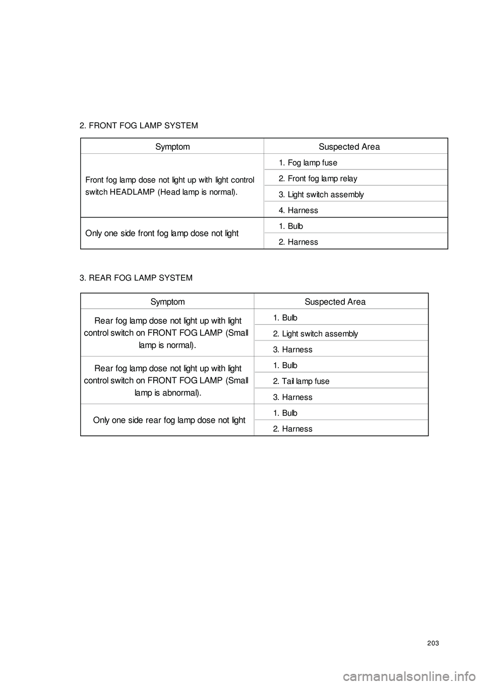
2032. FRONT FOG LAMP SYSTEM
3. REAR FOG LAMP SYSTEMSymptom Suspected Area
1. Fog la mp fuse
2. Front fog la mp rela y
3. Light switc h a ssembly
4. Harne ss
1. Bulb
2. Harne ss Front fog lamp dose not light up with light c ontrol
switch HEADLAMP (Head lamp is normal).
Only one side front fog la mp dose not lightSymptom Suspected Area
1. Bulb
2. Light switc h a ssembly
3. Harne ss
1. Bulb
2. T a il la mp f us e
3. Harne ss
1. Bulb
2. Harne ss Re a r fog lamp dose not light up with light
control switch on FRONT FOG LAMP (Small
la mp is nor ma l) .
Re a r fog lamp dose not light up with light
control switch on FRONT FOG LAMP (Small
la mp is abnormal).
Only one side rea r fog la mp dose not light
Page 256 of 392
249(3) Clear DTCs
When ECU diagnostic tester (Hi-DSTM) receives the "Clear DTCs" command from the serial interface,
the DTCs stored in ECU will be cleared off. But if an internal DTC is recorded or there is one crash
record, the command will not be executed.
5. Trouble display (Warning light ON)
(1) Light bulb check
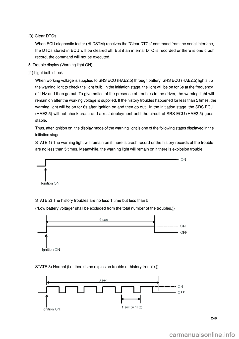
When working voltage is supplied to SRS ECU (HAE2.5) through battery, SRS ECU (HAE2.5) lights up
the warning light to check the light bulb. In the initiation stage, the light will be on for 6s at the frequency
of 1Hz and then go out. To give notice of the presence of troubles to the driver, the warning light will
remain on after the working voltage is supplied. If the history troubles happened for less than 5 times, the
warning light will be on for 6s after ignition on and then go out. In the initiation stage, the SRS ECU
(HAE2.5) will not check crash and arrest deployment until the circuit of SRS ECU (HAE2.5) goes
stable.
Thus, after ignition on, the display mode of the warning light is one of the following states displayed in the
initiation stage:
STATE 1) The warning light will remain on if there is crash record or the history records of the trouble
are no less than 5 times. Meanwhile, the warning light will remain on if there is explosion trouble.
STATE 2) The history troubles are no less 1 time but less than 5.
("Low battery voltage" shall be excluded from the total number of the troubles.))
STATE 3) Normal (i.e. there is no explosion trouble or history trouble.))
Page 257 of 392
250(2) Trouble indication
1In case of a trouble, the warning light will indicate. If the external trouble is a history trouble, the indication
will be cancelled. When the history trouble happens for no less than 5 times, the indicator light will remain
on even if there is no more trouble. "Low battery voltage" shall not be counted in the total number of
troubles.
2Only a service worker can reset a displayed or history trouble. The internal troubles of a SRS ECU
(HAE2.5) or the "crash record" of a trouble cannot be reset, in which case the SRS ECU (HAE2.5) shall
be replaced.
(3) Microcontroller-independent warning light on
Microcontroller with definitive troubles cannot fulfill its functions, thus cannot control the warning light. In
this case, the warning light will light up through proper circuit regardless of the microcontroller as stated
below:
�yMalfunction of the battery supplying power to SRS ECU (HAE2.5): the warning lights are turned
on continuously by means of the drive function of the selfcheck light.
�yLoss of internal working voltage: the warning light remains on.
�yReset due to trigger failure of the watchdog: the warning light blinks.
�yMicrocontroller out of work: the warning light always lights up.
�yIncomplete insertion of SRS ECU (HAE2.5) connector: the warning light remains on by means of
a shorting bar.
The diagnostic procedures can well be illustrated as follows:
If it is found that the SRS warning light remains on, follow the undermentioned procedures to check even if
the light goes out eventually. First, a scan meter is used to check the location of the trouble.
Then£¬go on with the checking in accordance with specific methods and procedures for the correspondent
location.
a. If the result indicates that it is an internal trouble or that the SRS is already detonated, replace the
ECU directly.
b. Troubleshooting.
Page 258 of 392
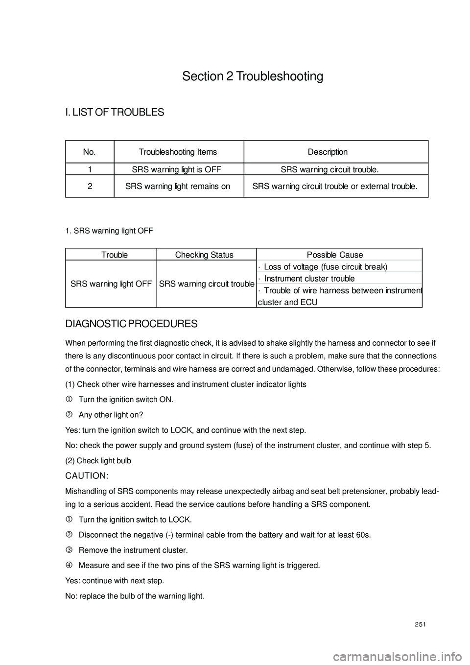
251Section 2 TroubleshootingI. LIST OF TROUBLES1. SRS warning light OFFDIAGNOSTIC PROCEDURESWhen performing the first diagnostic check, it is advised to shake slightly the harness and connector to see if
there is any discontinuous poor contact in circuit. If there is such a problem, make sure that the connections
of the connector, terminals and wire harness are correct and undamaged. Otherwise, follow these procedures:
(1) Check other wire harnesses and instrument cluster indicator lights
1Turn the ignition switch ON.
2Any other light on?
Yes: turn the ignition switch to LOCK, and continue with the next step.
No: check the power supply and ground system (fuse) of the instrument cluster, and continue with step 5.
(2) Check light bulb
CAUTION:
Mishandling of SRS components may release unexpectedly airbag and seat belt pretensioner, probably lead-
ing to a serious accident. Read the service cautions before handling a SRS component.
1Turn the ignition switch to LOCK.
2Disconnect the negative (-) terminal cable from the battery and wait for at least 60s.
3Remove the instrument cluster.
4Measure and see if the two pins of the SRS warning light is triggered.
Yes: continue with next step.
No: replace the bulb of the warning light.
Trouble Che c king Status P ossible Ca use
·Loss of voltage (fuse c irc uit bre a k)
·Instrument cluster trouble
·Trouble of wire harness between instrument
cluster and ECU SRS warning light OFF SRS wa rning c ircuit trouble1 SRS warning light is OFF SRS wa rning c irc uit trouble. No. Trouble shooting Ite ms De sc ription
2 SRS warning light re mains on SRS wa rning circ uit trouble or exte rna l trouble.