radiator GEELY CK 2008 Workshop Manual
[x] Cancel search | Manufacturer: GEELY, Model Year: 2008, Model line: CK, Model: GEELY CK 2008Pages: 392, PDF Size: 38.86 MB
Page 3 of 392
Chapter 6 Cooling System Inspection
(MR7131A, MR7151A, MR7161A).................................................................52Section 1 System Check
Section 2 Water Pump, Thermostat and Radiator Replacement.................................... 54Chapter 7 Clutch (MR7131A, MR7151A, MR7161A)....................................56Section 1 Clutch Replacement...................................................................................57Chapter 8 Maunal Transaxle Assembly
(MR7131A, MR7151A, MR7161A)................................................................59Section 1 Manual Transaxle Replacement..................................................................60
Section 2 Vehicle Speed Sensor Replacement
Section 3 Transmission Case Oil Seal..........................................................................62
Section 4 Transaxle Case Oil Seal Replacement........................................................63Chapter 9 General Engine Troubles and Their Troubleshooting....................64Section 1 Overview........................................................................................................64
Section 2 General Engine Fault and Troubleshooting.......................................................64
Section 3 Engine Noise Diagnosis and Troubleshooting................................................77Chapter 10 Engine Management Unit..............................................................81Section 1 System Description.........................................................................................81
Section 2 System Component and Working Principle......................................................82Part II Chassis............................................................................85Chapter 1 Transmission Control Device.........................................................85Section 1 Transmission Control Device.........................................................................85
Section 2 Lever Type Transmission Control Device......................................................85
Section 3 Cable Type Transmission Control Module......................................................87Chapter 2 Accelerator Pedal............................................................................90Section 1 Accelerator Pedal..........................................................................................90Chapter 3 Clutch Control System....................................................................91Section 1 Clutch Control System....................................................................................91
Section 2 Clutch Cable Control Mechanism.....................................................................91
Section 3 Clutch hydraulic Control Device.......................................................................94Chapter 4 Propeller Shaft...............................................................................97...............................................................................................52
..............................................................61
Page 17 of 392

10Chapter 2 Engine Components Replacement
(MR479Q, MR479QA, MR481QA)Section 1 Engine ComponentsComponent 1Air Filter Assembly W/ Hose
Accelerator Control
Cable Assembly
Heater Inlet Hose
Heater Outlet Hose
Fuel Sub-Assembly
Efi Fuel Pipe Clamp
MT:
Transmission
Control Cable
Assembly
AT :
Transmission Control Cable Assembly MT:
Clutch Release
Cylinder Assembly
Radiator Outlet Pipe Radiator Inlet Pipe
Starter AssemblyAT: Oil Cooler Outlet Pipe
AT: Oil Cooler Inlet Pipe
Radiator Assembly
BatteryFront Exhaust
Pipe Assy.3-way catalytic
converterMufflerTail PipeFigure 20
Page 21 of 392
1421. Remove radiator assembly
22. Remove engine V-belt
23. Remove No. 1 V- belt (A/C compressor to crankshaft pulley)
24. Remove generator assembly
25. Remove A/C compressor
26. Remove compressor installing No. 1 bracket. Remove 4 bolts and compressor installing No.
1 bracket.
27. Remove starter assembly
28. Remove power steering pump V- belt
29. Detach power steering pump assembly
30. Remove power steering pump, adjust the bracket
31. Detach manual transaxle assembly (Separate automatic transaxle assembly)
32. Detach clutch cover panel assembly.
33. Detach clutch pressure plate assembly.
34. Detach flywheel sub-assembly.
35. Remove engine rear end cover.
36. Remove injector assembly and remove intake manifold.
Remove 2 bolts and intake manifold support and remove 7 bolts,
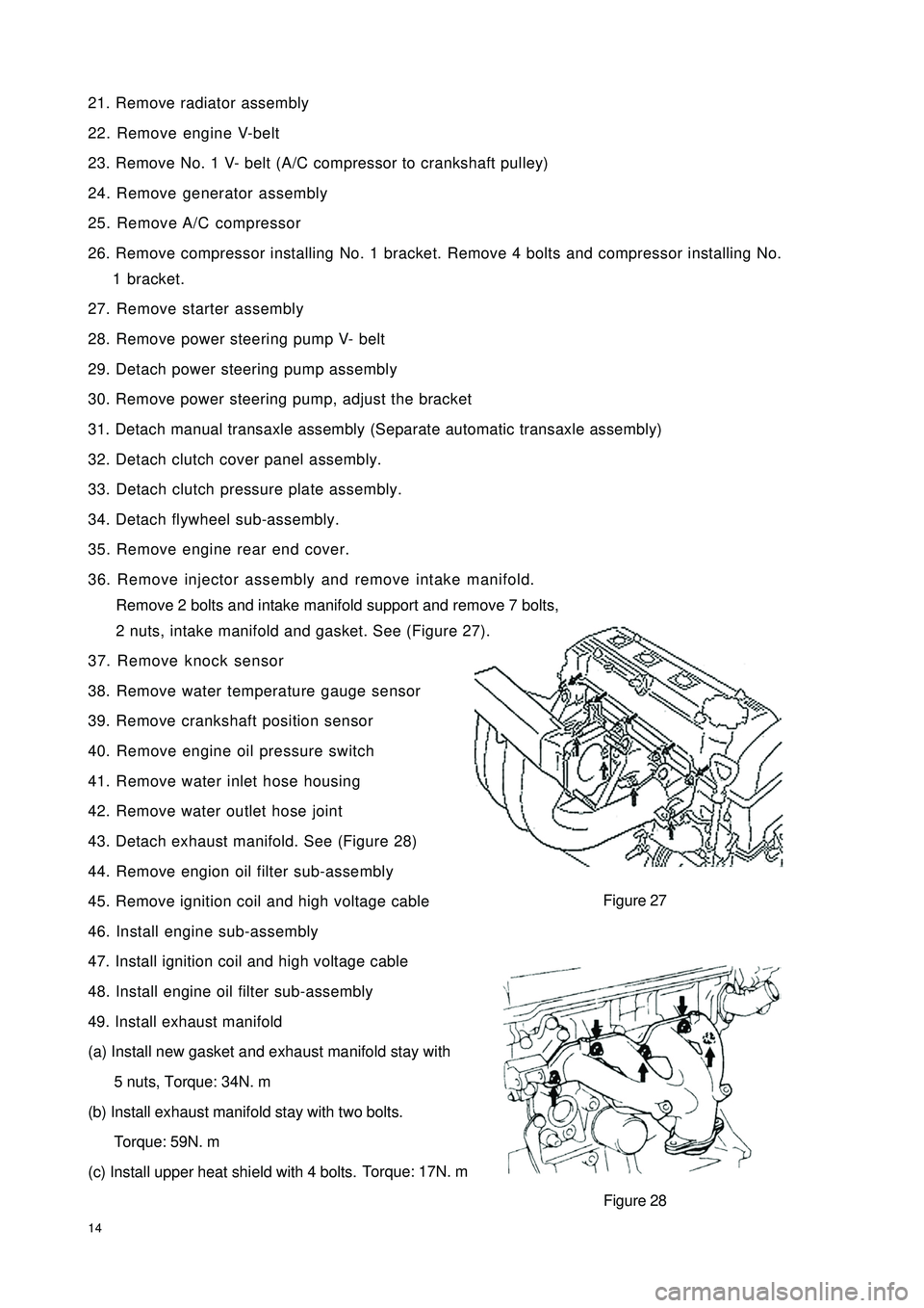
2 nuts, intake manifold and gasket. See (Figure 27).
37. Remove knock sensor
38. Remove water temperature gauge sensor
39. Remove crankshaft position sensor
40. Remove engine oil pressure switch
41. Remove water inlet hose housing
42. Remove water outlet hose joint
43. Detach exhaust manifold. See (Figure 28)
44. Remove engion oil filter sub-assembly
45. Remove ignition coil and high voltage cable
46. Install engine sub-assembly
47. Install ignition coil and high voltage cable
48. Install engine oil filter sub-assembly
49. Install exhaust manifold
(a) Install new gasket and exhaust manifold stay with
5 nuts, Torque: 34N. m
(b) Install exhaust manifold stay with two bolts.
Torque: 59N. m
(c) Install upper heat shield with 4 bolts.Torque: 17N. mFigure 27
Figure 28
Page 23 of 392
16(c) Install and uniformly tighten connecting bolt in the sequence shown inthe figure.
Torque: 64N. m
62. Install manual transaxle assembly
63. Install starter assembly
64. Install power steering pump bracket
65. Install power steering pump adjusting bracket with 2 bolts.
66. Connect power steering pump assembly
67. Install engine assembly and transaxle
68. Connect left, right, front and rear lower suspension arm sub-assembly
69. Connect left and right tie rod ball stud pin assembly
70. Connect left, right and front vehicle speed sensor (with ABS)
71. Install left & right nuts on the front shaft hub
72. Install front exhaust pipe assembly
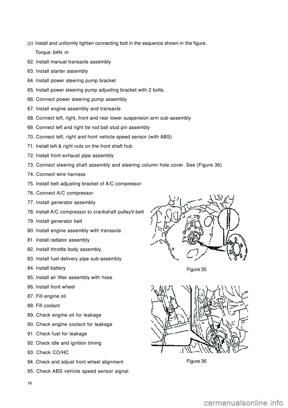
73. Connect steering shaft assembly and steering column hole cover. See (Figure 36)
74. Connect wire harness
75. Install belt adjusting bracket of A/C compressor
76. Connect A/C compressor
77. Install generator assembly
78. Install A/C compressor to crankshaft pulleyV-belt
79. Install generator belt
80. Install engine assembly with transaxle
81. Install radiator assembly
82. Install throttle body assembly
83. Install fuel delivery pipe sub-assembly
84. Install battery
85. Install air filter assembly with hose
86. Install front wheel
87. Fill engine oil
88. Fill coolant
89. Check engine oil for leakage
90. Check engine coolant for leakage
91. Check fuel for leakage
92. Check idle and ignition timing
93. Check CO/HC
94. Check and adjust front wheel alignment
95. Check ABS vehicle speed sensor signalFigure 35
Figure 36
Page 37 of 392

30Component 3Figure 70Air Filter Assembly W/ HoseEngine Hood
Right Wiper Arm
Left Wiper Arm
Right Scuttle Ventilation Grille
Left Scuttle Ventilation Grille Right Engine Mounting Bracket
Generator
AssemblyAccelerator Cable AssemblyWiper Arm Subassembly
EFI Fuel Hose Clamp
Fuel Pipe Sub-Assembly
Heater Outlet Hose A
Radiator Outlet Hose Radiator Inlet HoseHeater Inlet Hose
Vane-Type Pump
V-Belt V/ Power Steering
V-Belt No.1Fan & Generator V-Belt
Page 59 of 392
52Chapter 6 Cooling System Inspection
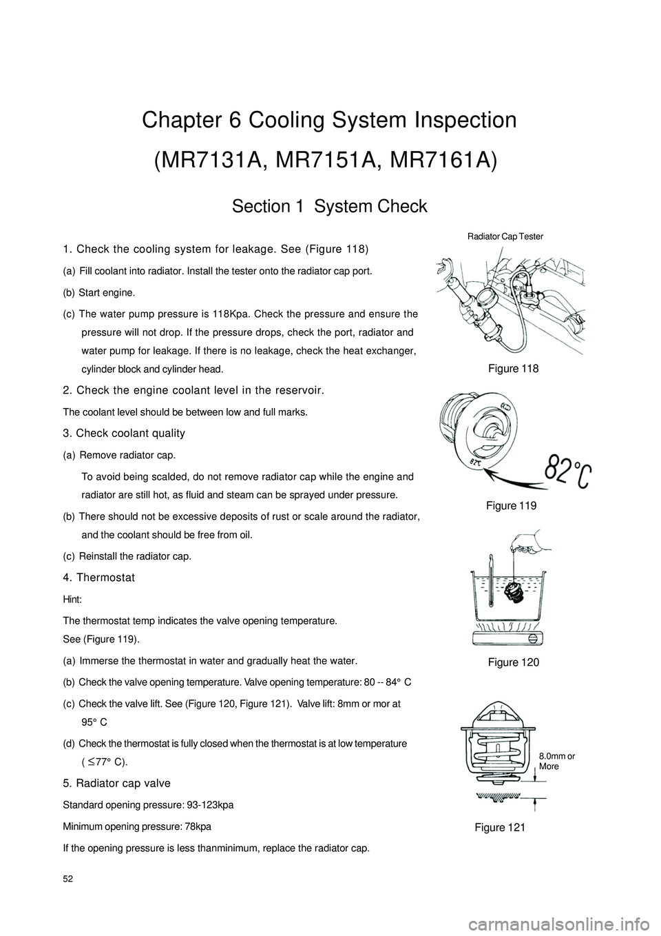
(MR7131A, MR7151A, MR7161A)Section 1 System Check1. Check the cooling system for leakage. See (Figure 118)
(a) Fill coolant into radiator. Install the tester onto the radiator cap port.
(b) Start engine.
(c) The water pump pressure is 118Kpa. Check the pressure and ensure the
pressure will not drop. If the pressure drops, check the port, radiator and
water pump for leakage. If there is no leakage, check the heat exchanger,
cylinder block and cylinder head.
2. Check the engine coolant level in the reservoir.
The coolant level should be between low and full marks.
3. Check coolant quality
(a) Remove radiator cap.
To avoid being scalded, do not remove radiator cap while the engine and
radiator are still hot, as fluid and steam can be sprayed under pressure.
(b) There should not be excessive deposits of rust or scale around the radiator,
and the coolant should be free from oil.
(c) Reinstall the radiator cap.
4. Thermostat
Hint:
The thermostat temp indicates the valve opening temperature.
See (Figure 119).
(a) Immerse the thermostat in water and gradually heat the water.
(b) Check the valve opening temperature. Valve opening temperature: 80 -- 84°C
(c) Check the valve lift. See (Figure 120, Figure 121). Valve lift: 8mm or mor at
95°C
(d) Check the thermostat is fully closed when the thermostat is at low temperature
( 77°C).
5. Radiator cap valve
Standard opening pressure: 93-123kpa
Minimum opening pressure: 78kpa
If the opening pressure is less thanminimum, replace the radiator cap.Figure 118
Figure 119
Figure 120
Figure 121 Radiator Cap Tester8.0mm or
More ≤
Page 61 of 392

54Section 2 Water Pump, Thermostat and Radiator ReplacementHoist the engine from the compartment. See "Provison 20, Section 2, Chapter 2".
1. Replace water pump. See (Figure 125)
(1) Drain the coolant.
(2) Detach timing belt.
(3) Detach power steering pump assembly.
(4) Remove the oil dipstick guide.
(5) Detach water pump assembly.
(6) Install water pump assembly.
(7) The installation is in the reverse order of the removal.
2. Replace thermostat
(1) Remove thermostat (See Figure 126).
(2) Install thermostat.
a. Install a new gasket to the thermostat. See (Figure 127).
b.Align the main valve of the thermostat to the top of the
stud. Insert the thermostat into the water inlet case.
Hint:
The main valve is set at around 10°C as shown in the figure. See (Figure 128).
(3) Install inlet connector.
Figure 127 Figure 128
3. Replace radiator
(1) Open radiator cap.
(2) Open the drain valve and drain the coolant.
(3) Detach radiator water inlet hose.
(4) Detach radiator water outlet hose.Figure 125
Figure 126
Page 62 of 392

55(5) Disconnect auto-transmission oil cooler input pipe (Auto-transmission).
(6) Disconnect auto-transmission oil cooler output pipe (Auto-transmission).
(7) Remove 4 bolts from the radiator mounting bracket. See (Figure 129).
(8) Detach radiator assembly, Remove 3 bolts. Detach the fan and fan shroud. See (Figure 130).
Figure 127 Figure 128
(9) Install the cooling fan assembly
(a) Fix the reservoir assembly on the cooling fan bracket with the bolt. Torque: 16 N. m.
(b) Install the fan and fan shroud with 3 bolts. Torque: 7.5N. m.
(c) Install the cooling fan assembly to radiator assembly with 3 bolts. Torque: 16N. m.
(d) Connect the overflow pipe on the reservoir assembly and radiator assembly. Fix it with the spring
band.
(f) The installation of the radiator assembly is in the reverse order of the removal.
Page 82 of 392
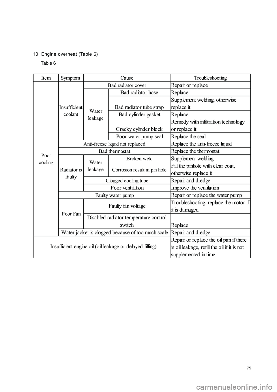
7510. Engine overheat (Table 6)
Table 6Ite m Symptom Trouble shootingRepair or replace
Bad radiator hose Replace
Bad radiator tube strapSupplement welding, otherwise
replace it
Bad cylinder gasket Replace
Cracky cylinder blockRemedy with infiltration technology
or replace it
Poor water pump seal Replace the seal
Replace the anti-freeze liquid
Replace the thermostatBroken we ldSupplement weldingCorrosion result in pin holeFill the pinhole with clear coat,
otherwise replace it
Repair and dredge
Improve the ventilation
Repair or replace the water pump
Troubleshooting, replace the motor if
it is d a ma ge d
Replace
Repair and dredge
Repair or replace the oil pan if there
is o il le a k a ge , r e fill t he o il if it is no t
s up p le me nt e d in t imeCause
Ba d ra diator c over
Clogge d cooling tubePoor ventilationWater
le a ka ge
Anti-fre eze liquid not repla ce d
Bad thermostat
Radiator is
faultyWater
le a ka ge Insufficient
coolantF a ulty fa n vo lta ge
Disabled radiator temperature control
switch
Water jacket is clogged because of too much scale
I ns uffic ie nt e ngine o il ( o il le a k a ge o r d e la ye d filling)P oor
c ooling
Poor FanFaulty water pump
Page 166 of 392
1594Make a simulation test in a way of symptom simulation
5Inspect DTC
6Confirm symptomV. SYMPTOM SIMULATIONNOTES:
The most difficult conditions to handle in the fault troubleshooting are that the fault symptom dose not appear.
Under the circumstances, make sure first to make a comprehensive analysis to the fault described by the
customer, then to simulate an environment that is similar or the same with the conditions when the fault of the
customer's vehicle occurred. No matter how rich the experience of the technician is and how skillful he is, if
he make a fault troubleshooting analysis without confirm the fault symptom, it is inevitable for him to neglect
some important factors and incorrectly guess, which may cause barriers to repair. For example, if a fault
occurs only when the engine is cool or if a fault occurs only caused by a vibration from pavement and so on,
when the engine is checked in the hot or static state, it is no way to confirm. Because of vibration, high-
temperature or seeping water (Vapor) often causes some faults that are difficult to reappear. So, here are
some effective symptom simulation tests.
KEY POINTS OF SYMPTOM SIMULATION TEST:
In the symptom simulation test, no doubt it is important to confirm the fault symptom, but the fault position or
fault components must be also found out. So, before the test and the pre-inspection of connection, narrow the
range of the circuit where faults may occur according to the fault symptom. Then make a symptom simula-
tion test to see if the circuit measured is normal; the fault symptom is also verified at the same time.
1. Way of Vibration: When vibration may be the major cause of the fault.
For example:
(a) Use your hand to gently vibrate the sensor that is considered the cause of the fault, in order to check if it
is ineffective.
(b) Softly rock the connector and harness in horizontal and vertical direction.
Notes: Hard rock may cause the relay circuit open.
2. Way of Spraying Water: When rainy weather or wet environment may be the major cause of the fault.
(a) Spray water on the vehicle to check if the fault occurs.
NOTES:
�yBe sure not to directly spray water into the engine compartment. Spray the water on the face of the
radiator to change the temperature and humidity indirectly.
�yBe sure not to spray water onto electronic devices and controllers.