refrigerant type GEELY CK 2008 Workshop Manual
[x] Cancel search | Manufacturer: GEELY, Model Year: 2008, Model line: CK, Model: GEELY CK 2008Pages: 392, PDF Size: 38.86 MB
Page 90 of 392

83ECU microcomputer consists of microprocessor, memory, clock generator, timer, I/O interface and input
level A/D converter that are integrated in a large scale integrated circuit chip, that is SCM (Single Chip
Microcomputer).
1. Input level
The input signals from the sensor are pre-processed by the input level. The input signals are sent to protected
circuit first, sometimes through the signal converter and amplifier, and then sent to microcomputer.
The sensor signal is separated into switch type and analog type. Ignition on/off signal, camshaft position
signal, vehicle speed signal and A/C signal are switch type; Signals such as battery voltage, engine temperature,
intake temperature, airflow, intake manifold absolute pressure, throttle opening, excessive air coefficient,
knock, A/C refrigerant pressure are analog type. Analogy signal can only be processed by the digital micro-
computer after being converted into digital signal by A/D converter. Hence, data collection shall be made
first for analog signal, and the sampling shall be maintained also.
Speed and crankshaft position reference signal from the sensor is processed in a dedicated circuit to restrain
the interference pulse.
2. Microcomputer
The microcomputer of the engine electronic control unit is integrated in a single chip microcomputer, consist-
ing of the following:
(1) Microprocessor, microprocessor is also called as central processing unit (CPU), consisting of the following
three parts:
Arithmetic logic unit.
Register group.
Controller.
(2) System assembly, The data transferred among the internal sections of the single chip microcomputer
(SCM) is performed on the internal bus, while that between the SCM and other components is performed
on the external bus. The external bus is also called system bus. It is separated into data bus, address bus
and control bus.
(3) Memory, the memory is designed to store the binary data. The primary components of the memory are:
Memory.
Data register.
Address register, address decoder.
a. Memory controller
(4) A/D converter
(5) I/O interface.
(6) Clock generator.
(7) Timer
(8) CAPCOM unit.
(9) Watchdog timer.
(10) Interrupt system.
Page 311 of 392

304Section 4 Service Caution & NoticeI. Service CautionRefrigerant Treatment
•During the treatment, the operator shall be careful not to inhale A/C refrigerant or lubricant vapor. Long-
term exposure to the A/C environment will cause the operator's eye, nose and throat liable to stimulation.
In addition, based on the consideration on the environment influence, when discharging the HFC-134a
from the A/C system, we suggest using the recyclable and rechargeable devices. If sudden system fault
occurs, it is recommended to place the device on a ventilated place before starting service.
•For HFC-134a service equipment, it is recommended not to perform the pressurization check or leakage
inspection. If these mixture combust, it may result in severe human injury or property loss.
•Please be noticed not to let the refrigerant leak near the spark or other hot objects. If the refrigerant gas
contacts the spark or similar heat source (e.g. cigarette or heater), it may generate poisonous gas. The
refrigerant is extremely liable to leakage during the transportation. In this case, please eliminate or remove
the heat source mentioned above and keep good ventilation.
•It is very dangerous to handle the liquid refrigerant. Only a drop of refrigerant can result in local frostbite
on skin if dropped on the skin of the operator. Therefore, it is specified that the operator shall always
wear glove and eye protection during the handling of the liquid refrigerant. If liquid refrigerant gets in
your eyes or on your skin, Wash the area with much cool water. Go immediately to hospital for professional
treatment.
Refrigerant Preservation
• Refrigerant preservation container is a high pressure resistant equipment. If it is put in hot treatment, the
explosion may arise, and the resulting metal fragments and the splashed liquid refrigerant will result in
severe human injury. It is recommended to preserve the refrigerant below 40°C.II. Service NoticeInsufficient Refrigerant Handling
•If the refrigerant is founded to be insufficient during the fault diagnosis, it is recommended not to add
refrigerant because of the following facts: the pressure readings indicated by different pressure gauge
are different, thus you will be unable to determine the exact amount of the refrigerant to be added, and
excessive or insufficient refrigerant may cause a series of chained negative effects such as damaged
refrigerant circulation parts or deteriorated refrigeration effect. Therefore, if the refrigerant is found to
be insufficient, it is recommended to drain the refrigerant from the refrigerant circulation pipeline and fill
specified amount of the refrigerant.
Compressor Oil Handling
•For this type of vehicle, it is recommended to use SW-100 type compressor oil. Use of PAG compressor
oil other than the SW-100 type may cause the A/C compressor to be damaged.
•During the operation, please be noticed not to splash the SW-100 type compressor oil onto the vehicle
surface. Therefore, if this happens, please wipe it off immediately, otherwise the compressor oil will
damage the paint on the vehicle surface.
Page 312 of 392

305•Compared with the early used mineral oil, the SW-100 type compressor oil is of comparatively high
moisture absorption performance. If you mix the moisture object with the SW-100 type compressor oil, it
will damage the Refrigeration system. Therefore, after treating the compressor oil or removing the
refrigeration system components, the lid shall be covered immediately to prevent the SW-100 type
compressor oil from absorbing the moisture.Section 5 The Refrigeration System Operation ProcedureI. Refill RefrigerantNotice:•During the filling of refrigerant into the refrigeration system, be careful that it is required to
have the professionals operate under the specified standard and procedure, otherwise it will
reduce the A/C efficiency greatly and even damage the refrigeration system components.
Refill the HFC-134a refrigerant
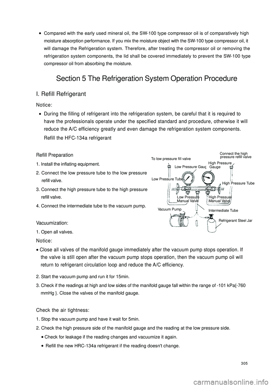
Refill Preparation1. Install the inflating equipment.
2. Connect the low pressure tube to the low pressure
refill valve.
3. Connect the high pressure tube to the high pressure
refill valve.
4. Connect the intermediate tube to the vacuum pump.Vacuumization:1. Open all valves.Notice:•Close all valves of the manifold gauge immediately after the vacuum pump stops operation. If
the valve is still open after the vacuum pump stops operation, then the vacuum pump oil will
return to refrigerant circulation loop and reduce the A/C efficiency.2. Start the vacuum pump and run it for 15min.
3. Check if the readings at high and low sides of the manifold gauge fall within the range of -101 kPa{-760
mmHg }. Close the valves of the manifold gauge.Check the air tightness:1. Stop the vacuum pump and have it wait for 5min.
2. Check the high pressure side of the manifold gauge and the reading at the low pressure side.
•Check for leakage if the reading changes and vacuumize it again.
•Refill the new HRC-134a refrigerant if the reading doesn't change.To low pressure fill valveLow Pressure GaugeHigh Pressure
GaugeConnect the high
pressure refill valveLow Pressure TubeHigh Pressure TubeLow Pressure
Manual ValveHigh Pressure
Manual ValveVacuum PumpIntermediate Tube
Refrigerant Steel Jar
Page 318 of 392

311Check the condenser1. Check for crack, damage or oil leakage.
•Replace the condenser if any of the above-mentioned faults occurs.
2. Check if the fin area is blocked by dust.
•Clean it if it is blocked.
3. Check if the fin area bends.
•If the fin area bends, level it with a flat head screwdriver.6. Refrigeration Pipeline Removal / Installation1. Remove battery.
2. Drain the refrigerant from the system.
3. Remove air filter.
4. Remove the clamp.
5. Remove the compressor inlet hose.
6. Remove the compressor outlet hose.
7. Remove liquid pipe I.
8. Remove pressure switch connector.
9. Remove the pipe clamp.
10. Remove liquid pipe II.
11. The installation is in the reverse order of the removal.Notice:•If anything moisture or any foreign matter enters into the Refrigeration system for circulation,
the cooling performance of the Refrigeration system will obviously deteriorate with abnormal
noise. Plug the port immediately after removing any cooling circulation component to prevent
anything moistur or any foreign matter from entering the circulation.
Introduction Of The Refrigeration Pipeline Removal:
Nuts union type:Loose the nuts with 2 wrenches and then remove the refrigeration pipe (or the hose).Slider joint type:Clip the slider block recess end with pliers or the similar tool and remove the attaching bolt or screw cap.