wheel torque GEELY CK 2008 Workshop Manual
[x] Cancel search | Manufacturer: GEELY, Model Year: 2008, Model line: CK, Model: GEELY CK 2008Pages: 392, PDF Size: 38.86 MB
Page 21 of 392
1421. Remove radiator assembly
22. Remove engine V-belt
23. Remove No. 1 V- belt (A/C compressor to crankshaft pulley)
24. Remove generator assembly
25. Remove A/C compressor
26. Remove compressor installing No. 1 bracket. Remove 4 bolts and compressor installing No.
1 bracket.
27. Remove starter assembly
28. Remove power steering pump V- belt
29. Detach power steering pump assembly
30. Remove power steering pump, adjust the bracket
31. Detach manual transaxle assembly (Separate automatic transaxle assembly)
32. Detach clutch cover panel assembly.
33. Detach clutch pressure plate assembly.
34. Detach flywheel sub-assembly.
35. Remove engine rear end cover.
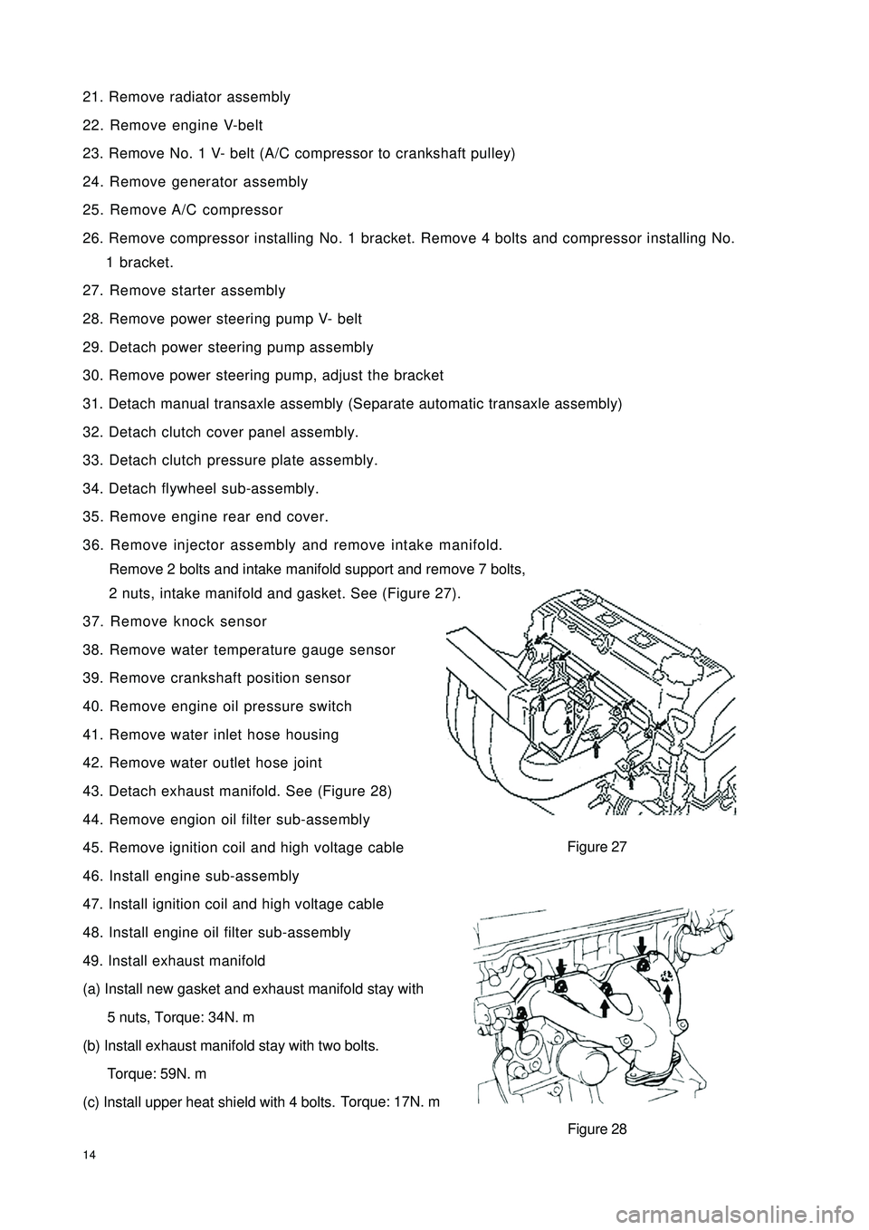
36. Remove injector assembly and remove intake manifold.
Remove 2 bolts and intake manifold support and remove 7 bolts,
2 nuts, intake manifold and gasket. See (Figure 27).
37. Remove knock sensor
38. Remove water temperature gauge sensor
39. Remove crankshaft position sensor
40. Remove engine oil pressure switch
41. Remove water inlet hose housing
42. Remove water outlet hose joint
43. Detach exhaust manifold. See (Figure 28)
44. Remove engion oil filter sub-assembly
45. Remove ignition coil and high voltage cable
46. Install engine sub-assembly
47. Install ignition coil and high voltage cable
48. Install engine oil filter sub-assembly
49. Install exhaust manifold
(a) Install new gasket and exhaust manifold stay with
5 nuts, Torque: 34N. m
(b) Install exhaust manifold stay with two bolts.
Torque: 59N. m
(c) Install upper heat shield with 4 bolts.Torque: 17N. mFigure 27
Figure 28
Page 22 of 392
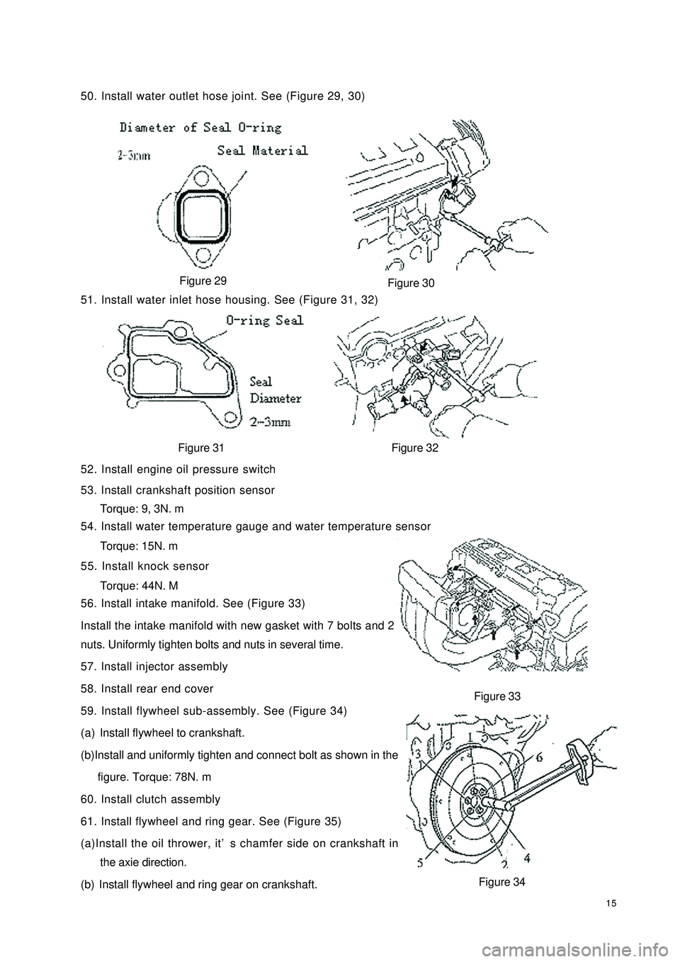
1550. Install water outlet hose joint. See (Figure 29, 30)
Figure 29
51. Install water inlet hose housing. See (Figure 31, 32)
Figure 31 Figure 32
52. Install engine oil pressure switch
53. Install crankshaft position sensor
Torque: 9, 3N. m
54. Install water temperature gauge and water temperature sensor
Torque: 15N. m
55. Install knock sensor
Torque: 44N. M
56. Install intake manifold. See (Figure 33)
Install the intake manifold with new gasket with 7 bolts and 2
nuts. Uniformly tighten bolts and nuts in several time.
57. Install injector assembly
58. Install rear end cover
59. Install flywheel sub-assembly. See (Figure 34)
(a) Install flywheel to crankshaft.
(b)Install and uniformly tighten and connect bolt as shown in the
figure. Torque: 78N. m
60. Install clutch assembly
61. Install flywheel and ring gear. See (Figure 35)
(a)Install the oil thrower, it’s chamfer side on crankshaft in
the axie direction.
(b) Install flywheel and ring gear on crankshaft.Figure 33
Figure 34 Figure 30
Page 23 of 392
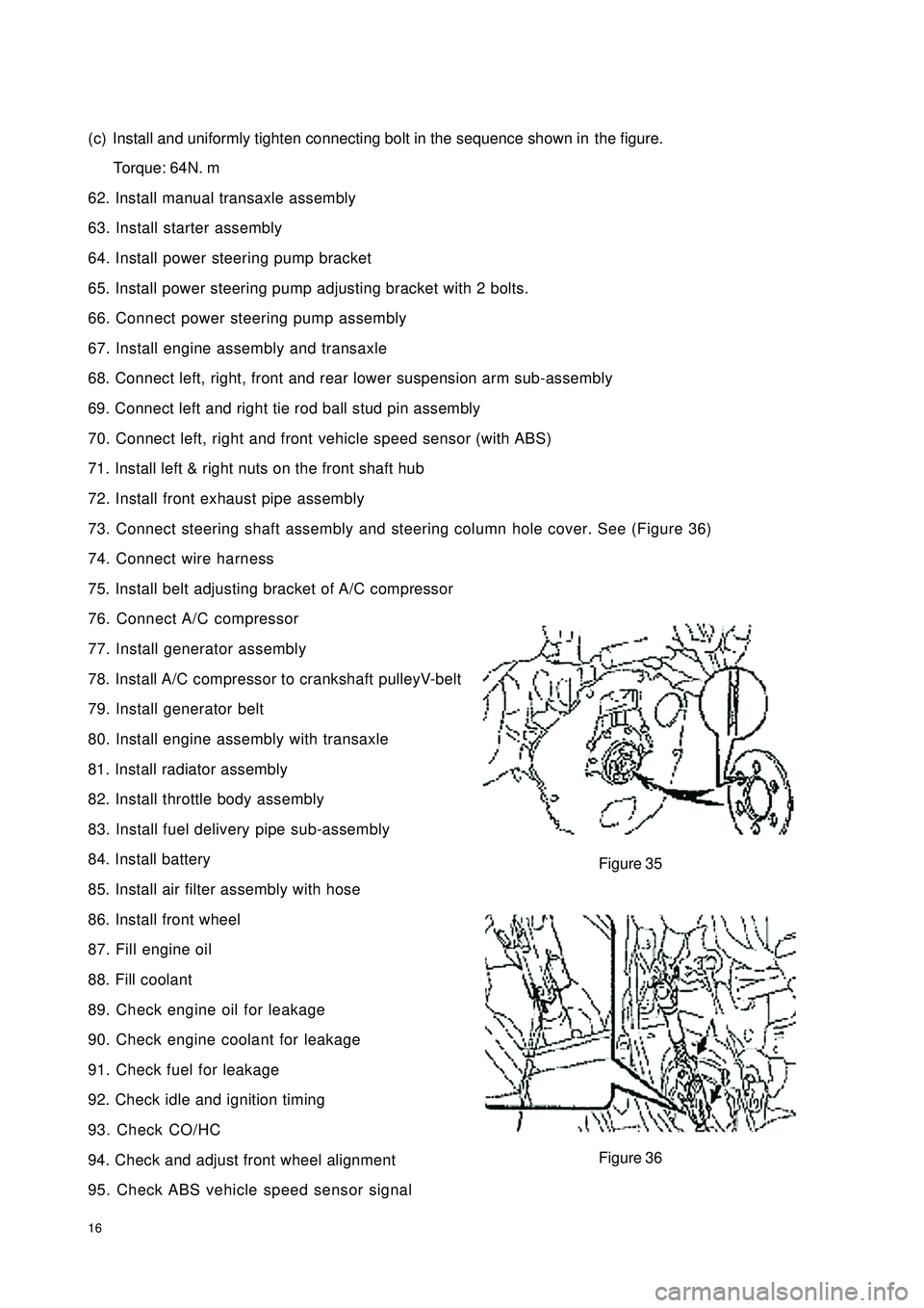
16(c) Install and uniformly tighten connecting bolt in the sequence shown inthe figure.
Torque: 64N. m
62. Install manual transaxle assembly
63. Install starter assembly
64. Install power steering pump bracket
65. Install power steering pump adjusting bracket with 2 bolts.
66. Connect power steering pump assembly
67. Install engine assembly and transaxle
68. Connect left, right, front and rear lower suspension arm sub-assembly
69. Connect left and right tie rod ball stud pin assembly
70. Connect left, right and front vehicle speed sensor (with ABS)
71. Install left & right nuts on the front shaft hub
72. Install front exhaust pipe assembly
73. Connect steering shaft assembly and steering column hole cover. See (Figure 36)
74. Connect wire harness
75. Install belt adjusting bracket of A/C compressor
76. Connect A/C compressor
77. Install generator assembly
78. Install A/C compressor to crankshaft pulleyV-belt
79. Install generator belt
80. Install engine assembly with transaxle
81. Install radiator assembly
82. Install throttle body assembly
83. Install fuel delivery pipe sub-assembly
84. Install battery
85. Install air filter assembly with hose
86. Install front wheel
87. Fill engine oil
88. Fill coolant
89. Check engine oil for leakage
90. Check engine coolant for leakage
91. Check fuel for leakage
92. Check idle and ignition timing
93. Check CO/HC
94. Check and adjust front wheel alignment
95. Check ABS vehicle speed sensor signalFigure 35
Figure 36
Page 26 of 392
1920. Remove timing belt guide wheel
Hint:
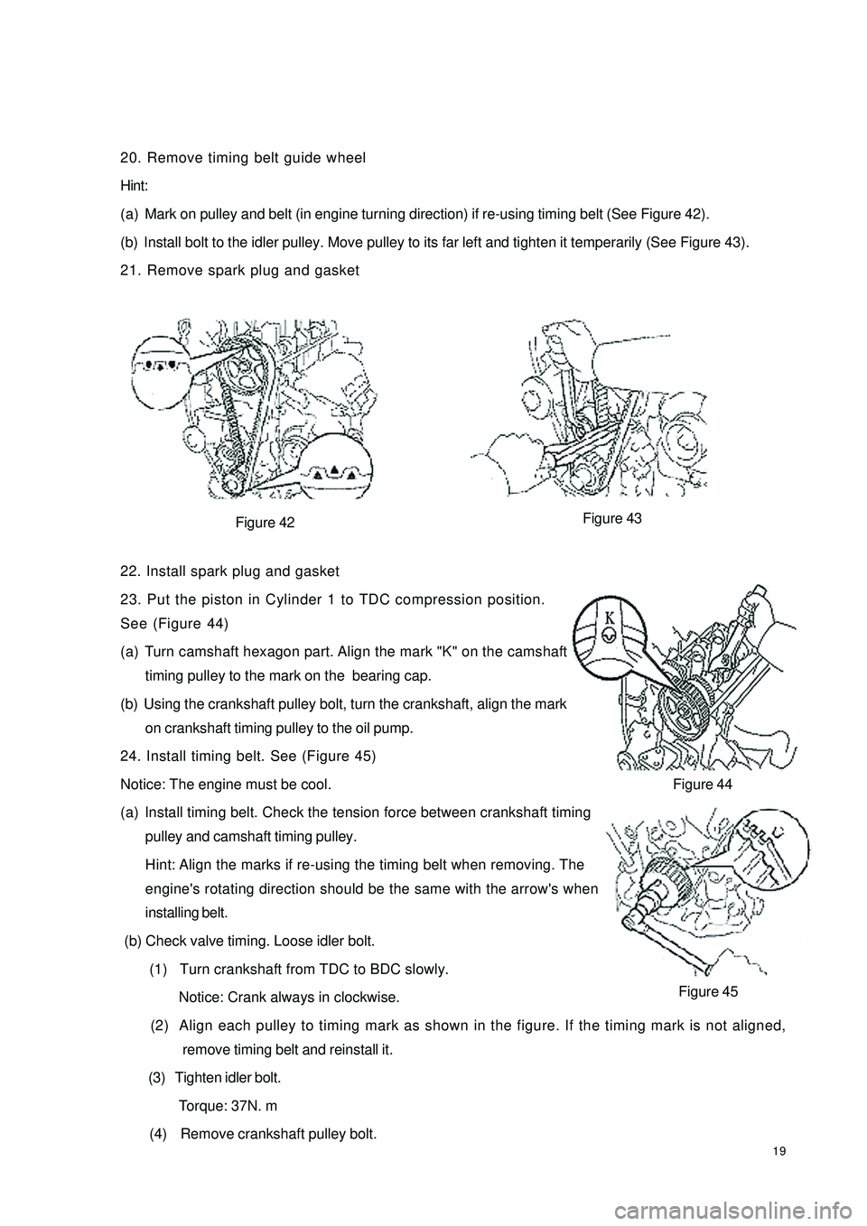
(a) Mark on pulley and belt (in engine turning direction) if re-using timing belt (See Figure 42).
(b) Install bolt to the idler pulley. Move pulley to its far left and tighten it temperarily (See Figure 43).
21. Remove spark plug and gasket
Figure 42
22. Install spark plug and gasket
23. Put the piston in Cylinder 1 to TDC compression position.
See (Figure 44)
(a) Turn camshaft hexagon part. Align the mark "K" on the camshaft
timing pulley to the mark on the bearing cap.
(b) Using the crankshaft pulley bolt, turn the crankshaft, align the mark
on crankshaft timing pulley to the oil pump.
24. Install timing belt. See (Figure 45)
Notice: The engine must be cool.
(a) Install timing belt. Check the tension force between crankshaft timing
pulley and camshaft timing pulley.
Hint: Align the marks if re-using the timing belt when removing. The
engine's rotating direction should be the same with the arrow's when
installing belt.
(b) Check valve timing. Loose idler bolt.
(1) Turn crankshaft from TDC to BDC slowly.
Notice: Crank always in clockwise.
(2) Align each pulley to timing mark as shown in the figure. If the timing mark is not aligned,
remove timing belt and reinstall it.
(3) Tighten idler bolt.
Torque: 37N. m
(4) Remove crankshaft pulley bolt.Figure 44
Figure 45 Figure 43
Page 27 of 392
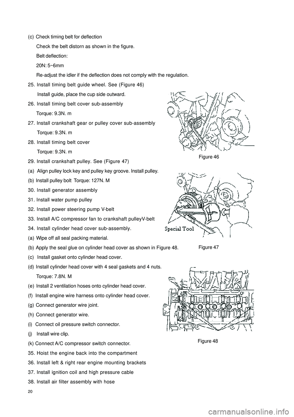
20(c) Check timing belt for deflection
Check the belt distorn as shown in the figure.
Belt deflection:
20N: 5~6mm
Re-adjust the idler if the deflection does not comply with the regulation.
25. Install timing belt guide wheel. See (Figure 46)
Install guide, place the cup side outward.
26. Install timing belt cover sub-assembly
Torque: 9.3N. m
27. Install crankshaft gear or pulley cover sub-assembly
Torque: 9.3N. m
28. Install timing belt cover
Torque: 9.3N. m
29. Install crankshaft pulley. See (Figure 47)
(a) Align pulley lock key and pulley key groove. Install pulley.
(b) Install pulley bolt Torque: 127N. M
30. Install generator assembly
31. Install water pump pulley
32. Install power steering pump V-belt
33. Install A/C compressor fan to crankshaft pulleyV-belt
34. Install cylinder head cover sub-assembly.
(a) Wipe off all seal packing material.
(b) Apply the seal glue on cylinder head cover as shown in Figure 48.
(c) Install gasket onto cylinder head cover.
(d) Install cylinder head cover with 4 seal gaskets and 4 nuts.
Torque: 7.8N. M
(e) Install 2 ventilation hoses onto cylinder head cover.
(f) Install engine wire harness onto cylinder head cover.
(g) Connect generator wire joint.
(h) Connect generator wire.
(i) Connect oil pressure switch connector.
(j) Install wire clip.
(k) Connect A/C compressor switch connector.
35. Hoist the engine back into the compartment
36. Install left & right rear engine mounting brackets
37. Install ignition coil and high pressure cable
38. Install air filter assembly with hoseFigure 48Figure 46
Figure 47
Page 41 of 392
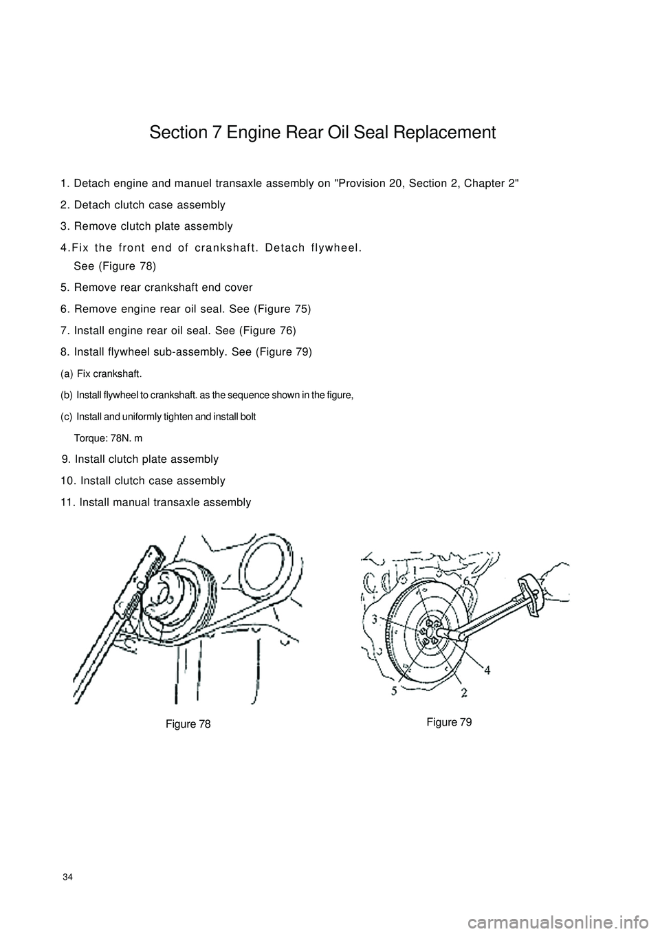
34Section 7 Engine Rear Oil Seal Replacement1. Detach engine and manuel transaxle assembly on "Provision 20, Section 2, Chapter 2"
2. Detach clutch case assembly
3. Remove clutch plate assembly
4.Fix the front end of crankshaft. Detach flywheel.
See (Figure 78)
5. Remove rear crankshaft end cover
6. Remove engine rear oil seal. See (Figure 75)
7. Install engine rear oil seal. See (Figure 76)
8. Install flywheel sub-assembly. See (Figure 79)
(a) Fix crankshaft.
(b) Install flywheel to crankshaft. as the sequence shown in the figure,
(c) Install and uniformly tighten and install bolt
Torque: 78N. m
9. Install clutch plate assembly
10. Install clutch case assembly
11. Install manual transaxle assembly
Figure 78Figure 79
Page 65 of 392
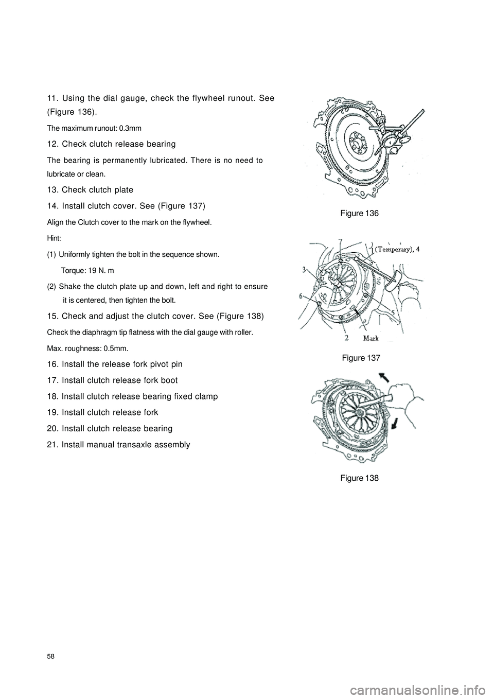
5811. Using the dial gauge, check the flywheel runout. See
(Figure 136).
The maximum runout: 0.3mm
12. Check clutch release bearing
The bearing is permanently lubricated. There is no need to
lubricate or clean.
13. Check clutch plate
14. Install clutch cover. See (Figure 137)
Align the Clutch cover to the mark on the flywheel.
Hint:
(1) Uniformly tighten the bolt in the sequence shown.
Torque: 19 N. m
(2) Shake the clutch plate up and down, left and right to ensure
it is centered, then tighten the bolt.
15. Check and adjust the clutch cover. See (Figure 138)
Check the diaphragm tip flatness with the dial gauge with roller.
Max. roughness: 0.5mm.
16. Install the release fork pivot pin
17. Install clutch release fork boot
18. Install clutch release bearing fixed clamp
19. Install clutch release fork
20. Install clutch release bearing
21. Install manual transaxle assemblyFigure 136
Figure 137
Figure 138
Page 109 of 392
102(7) Install front wheel, wheel nut torque: 95~115N.m
(8) Make sure that the propeller shafts for 1.3L engine and 1.5L engine are not interchanged
at the time of replacement
(9) Check the ABS sensor signal, check and adjust the front wheel alignment if necessary.
Page 113 of 392
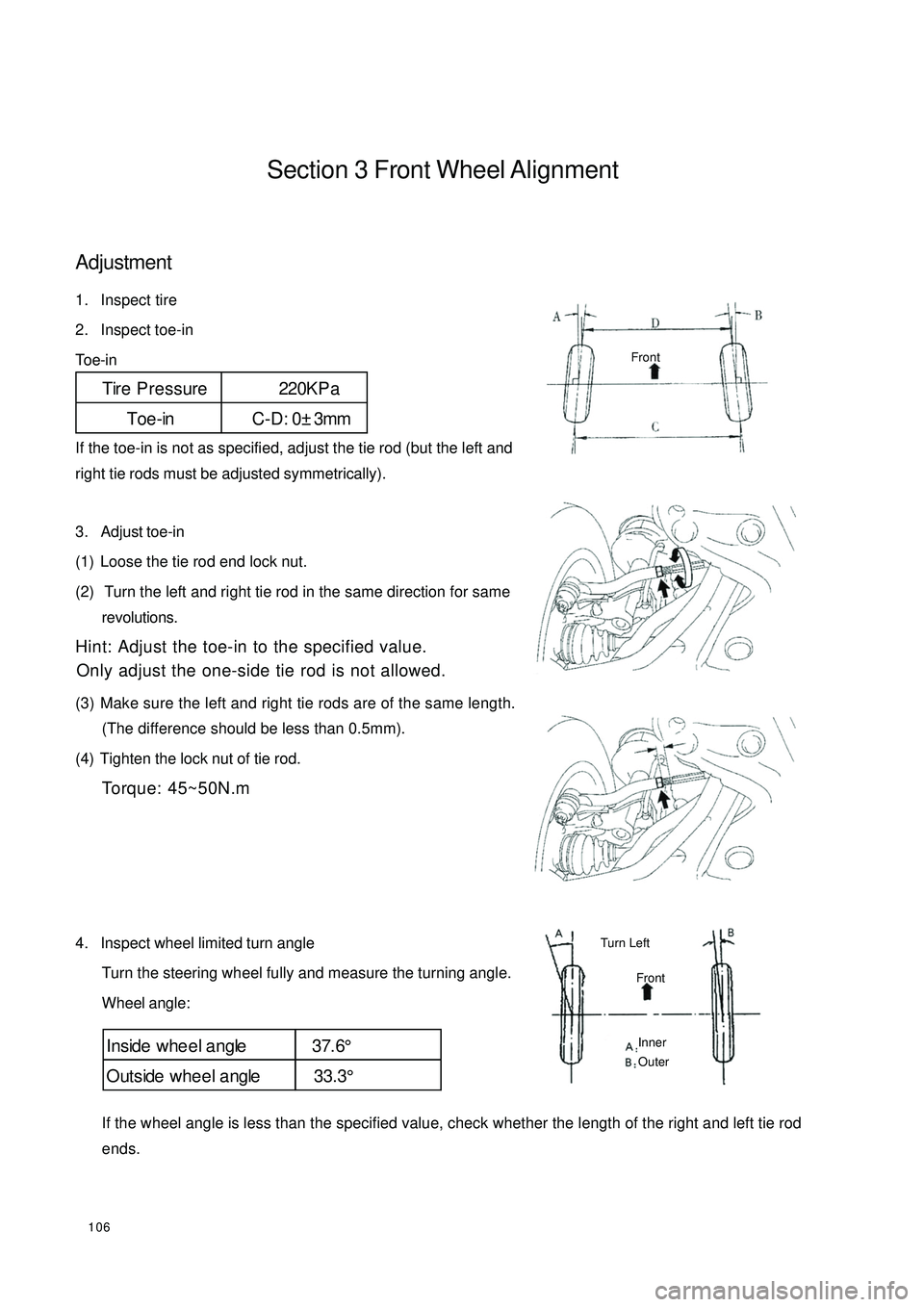
106Section 3 Front Wheel AlignmentAdjustment1. Inspect tire
2. Inspect toe-in
Toe-in
If the toe-in is not as specified, adjust the tie rod (but the left and
right tie rods must be adjusted symmetrically).
3. Adjust toe-in
(1) Loose the tie rod end lock nut.
(2) Turn the left and right tie rod in the same direction for same
revolutions.
Hint: Adjust the toe-in to the specified value.
Only adjust the one-side tie rod is not allowed.
(3) Make sure the left and right tie rods are of the same length.
(The difference should be less than 0.5mm).
(4) Tighten the lock nut of tie rod.
Torque: 45~50N.m
4. Inspect wheel limited turn angle
Turn the steering wheel fully and measure the turning angle.
Wheel angle:
If the wheel angle is less than the specified value, check whether the length of the right and left tie rod
ends.Tire Pressure 220KP a
Toe-in C-D: 0±3mmInside whe e l a ngle 37.6°
Outside whee l a ngle 33.3°FrontFrontTurn Left Inner
Outer
Page 119 of 392
1123. Remove lower swing arm front support frame
Remove the 4 bolts connecting the lower swing arm front support frame and vehicle body.
4. Disassemble lower swing arm assembly
Disassembly of lower swing arm assembly is in the reverse order of the assembly.
Notice: Do not tighten type 1 hexagon nut
5. Install lower swing arm front support frame
Attach the lower swing arm front support frame to the vehicle body with bolts .
Torque: 80~90N.m
6. Install lower swing arm assembly
(1) Install the bolts and nuts connecting the lower swing arm assembly and lower swing arm front support
frame.
Notice: Do not tighten the bolts
(2) Attach the left lower swing arm assembly ball stud pin to the steering knuckle with bolts and nuts.
Torque: 80~90N.m
(3) Install the attaching bolt between the lower swing arm rear spring joint cover and the body.
Torque: 80~90N.m
7. Set nut
(1) Lower the vehicle and center the front wheel.
Be careful of the security
(2) Tighten the bolts connecting lower swing arm assembly and lower swing arm front support frame
Torque: 90~100N.m
(3) Tighten the set nuts on the lower swing arm assembly rear spring joint
Torque: 90~100N.m