suspension GEELY CK 2008 Workshop Manual
[x] Cancel search | Manufacturer: GEELY, Model Year: 2008, Model line: CK, Model: GEELY CK 2008Pages: 392, PDF Size: 38.86 MB
Page 4 of 392
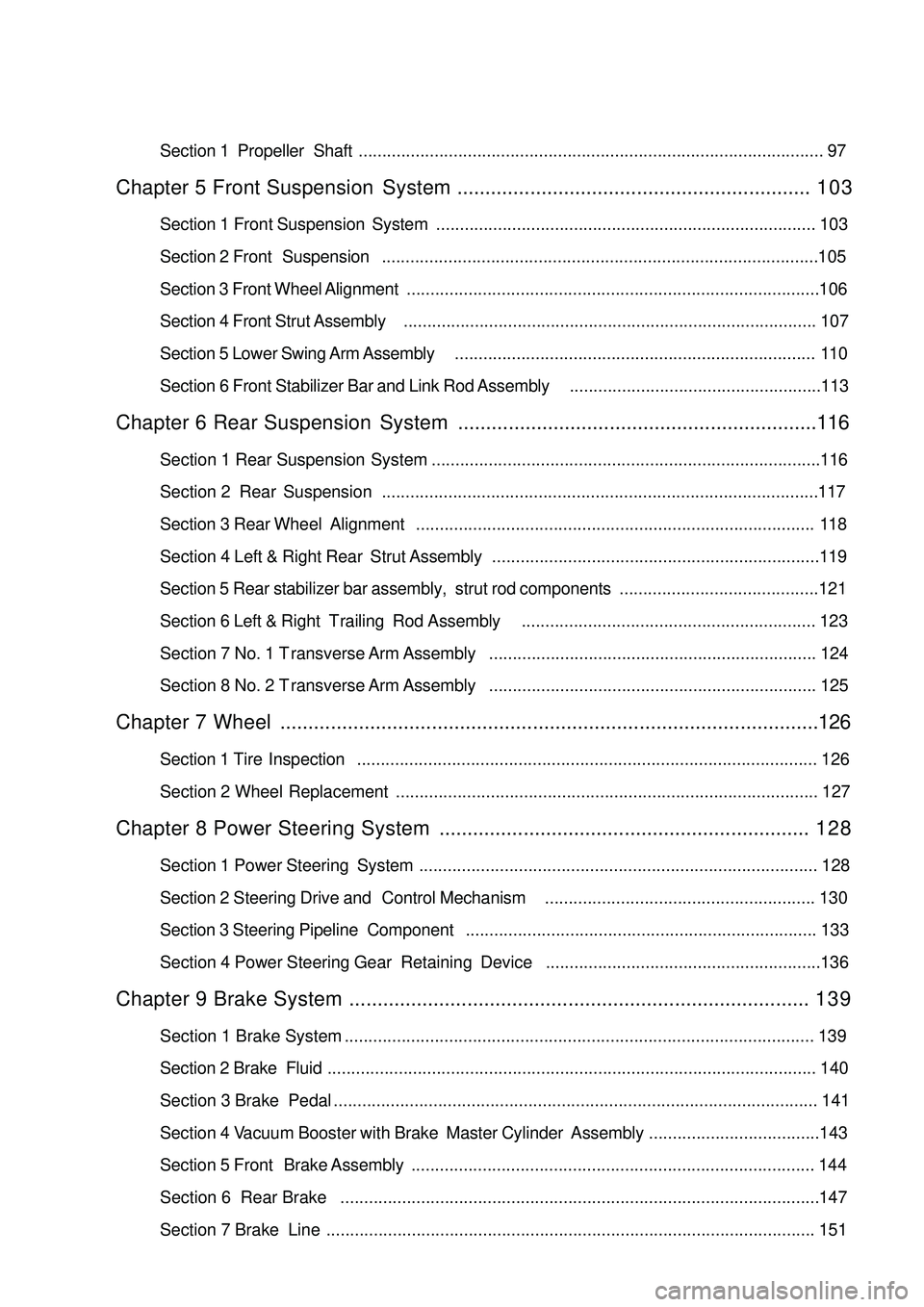
Section 1 Propeller Shaft.................................................................................................. 97Chapter 5 Front Suspension System............................................................... 1 0 3Section 1 Front Suspension System................................................................................ 103
Section 2 Front Suspension............................................................................................105
Section 3 Front Wheel Alignment.......................................................................................106
Section 4 Front Strut Assembly....................................................................................... 107
Section 5 Lower Swing Arm Assembly............................................................................ 110
Section 6 Front Stabilizer Bar and Link Rod Assembly.....................................................113Chapter 6 Rear Suspension System................................................................116Section 1 Rear Suspension System
Section 2 Rear Suspension............................................................................................117
Section 3 Rear Wheel Alignment.................................................................................... 118
Section 4 Left & Right Rear Strut Assembly.....................................................................119
Section 5 Rear stabilizer bar assembly, strut rod components..........................................121
Section 6 Left & Right Trailing Rod Assembly.............................................................. 123
Section 7 No. 1 Transverse Arm Assembly..................................................................... 124
Section 8 No. 2 Transverse Arm Assembly..................................................................... 125Chapter 7 Wheel................................................................................................126Section 1 Tire Inspection................................................................................................. 126
Section 2 Wheel Replacement......................................................................................... 127Chapter 8 Power Steering System.................................................................. 1 2 8Section 1 Power Steering System.................................................................................... 128
Section 2 Steering Drive and Control Mechanism......................................................... 130
Section 3 Steering Pipeline Component.......................................................................... 133
Section 4 Power Steering Gear Retaining DeviceChapter 9 Brake System.................................................................................. 1 3 9Section 1 Brake System ................................................................................................... 139
Section 2 Brake Fluid....................................................................................................... 140
Section 3 Brake Pedal...................................................................................................... 141
Section 4 Vacuum Booster with Brake Master Cylinder Assembly....................................143
Section 5 Front Brake Assembly..................................................................................... 144
Section 6 Rear Brake
Section 7 Brake Line ....................................................................................................... 151..................................................................................116
.....................................................................................................147..........................................................136
Page 23 of 392
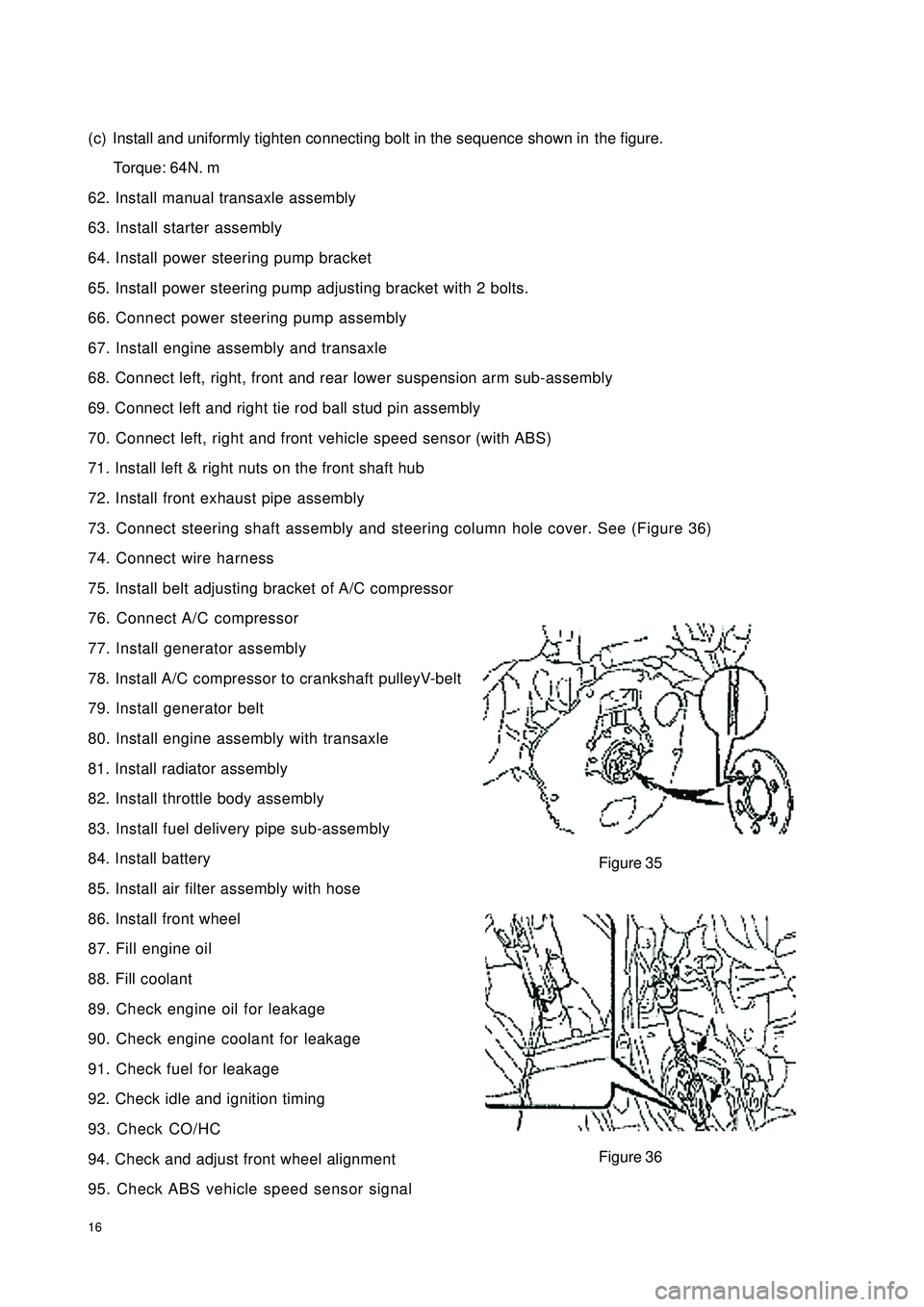
16(c) Install and uniformly tighten connecting bolt in the sequence shown inthe figure.
Torque: 64N. m
62. Install manual transaxle assembly
63. Install starter assembly
64. Install power steering pump bracket
65. Install power steering pump adjusting bracket with 2 bolts.
66. Connect power steering pump assembly
67. Install engine assembly and transaxle
68. Connect left, right, front and rear lower suspension arm sub-assembly
69. Connect left and right tie rod ball stud pin assembly
70. Connect left, right and front vehicle speed sensor (with ABS)
71. Install left & right nuts on the front shaft hub
72. Install front exhaust pipe assembly
73. Connect steering shaft assembly and steering column hole cover. See (Figure 36)
74. Connect wire harness
75. Install belt adjusting bracket of A/C compressor
76. Connect A/C compressor
77. Install generator assembly
78. Install A/C compressor to crankshaft pulleyV-belt
79. Install generator belt
80. Install engine assembly with transaxle
81. Install radiator assembly
82. Install throttle body assembly
83. Install fuel delivery pipe sub-assembly
84. Install battery
85. Install air filter assembly with hose
86. Install front wheel
87. Fill engine oil
88. Fill coolant
89. Check engine oil for leakage
90. Check engine coolant for leakage
91. Check fuel for leakage
92. Check idle and ignition timing
93. Check CO/HC
94. Check and adjust front wheel alignment
95. Check ABS vehicle speed sensor signalFigure 35
Figure 36
Page 110 of 392
103Chapter 5 Front Suspension SystemSection 1 Front Suspension SystemDescription on front suspension structure
This model uses strut swing arm independent suspension with stabilizer bar.
The shock absorber upper end is flexibly connected to the body through the shock absorber mounting seat,
the lower end is rigidly connected to the steering knuckle. The coil spring encloses the shock absorber (coil
spring geometrical axial line does not coincide with that of the shock absorber piston rod), and is supported
between the upper and lower spring seats.
Both ends of the stabilizer bar are connected to the shock absorber through the strut bar ball pin and the
intermediate part is supported on the lower front body by the rubber bushing and support frame.
The front cushion sleeves the shock absorber piston rod head to restrict the wheel jump limit position and
plays the role of buffer.
The thrust ball bearing, installed between the spring upper seat and the shock absorber mount, is used for the
relative rotation upon steering of the shock absorber rigidly connected to the steering knuckle to the shock
absorber mount flexibly connected to the body.
"L" type lower swing arm is secured to the lower engine compartment with the press plate through elastic
rubber bushing and hinge, and its outer end is connected to the steering knuckle through the ball stud pin
which is attached to the lower swing arm by 3 high intension bolts. The ball stud pin can be removed and
replaced when it is worn.
The ball seat material is saturated polyester containing oil, featured in comparatively high intensity and
wearability and good self-lubrication performance. Proper amount of grease has been added during the
assembly and there is no need for additional filling during the normal operation.
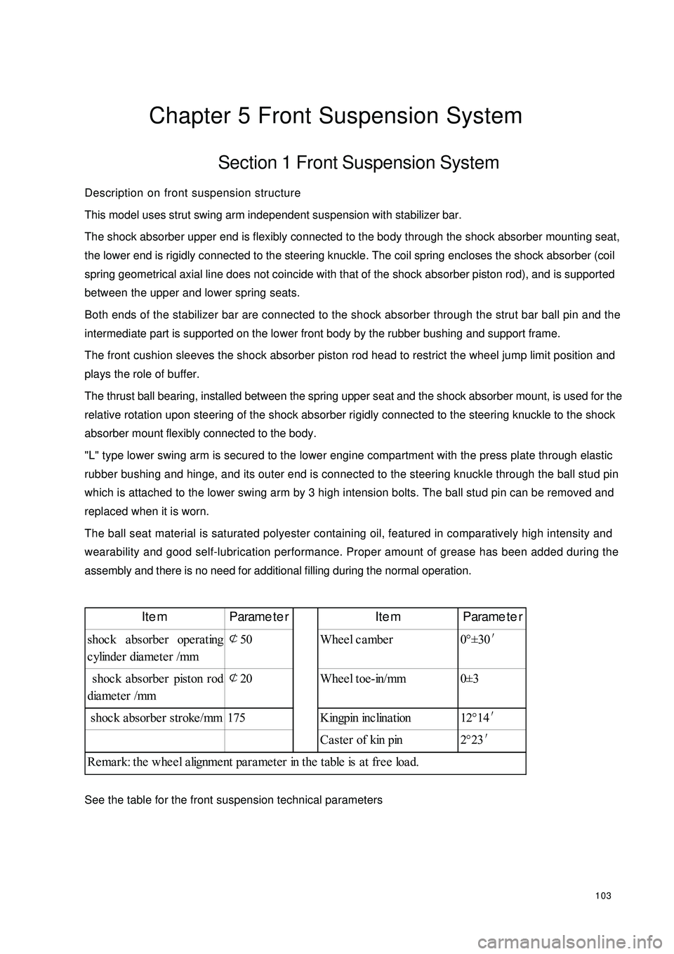
See the table for the front suspension technical parametersItem Parameter Item Parameter
shoc k a bsorbe r ope ra ting
cylinder diameter /mm¢
50 Wheel camber 0°±30′
shoc k a bsorbe r piston rod
diameter /mm¢
20 Wheel toe-in/mm 0±3
shoc k a bsorbe r stroke /mm 175 Kingpin inc lina tion 12°14′
Ca ste r of kin pin 2°23′
Remark: the wheel alignment parameter in the table is at free load.
Page 112 of 392

105Section 2 Front SuspensionComponents
LF Strut Assembly
Front
Brake Hose Clip
Connected to Brake
Connected
to Brake
LF Brake Assembly
Stabilizer Bar
Left Link Rod
Assembly
Left lower Swing
Arm Assembly
Lower Swing
Arm LF Bracket
Lower Swing Arm
RF Bracket
Front Stabilizer Bar Assembly
Stabilizer Bar
Right Link Rod Assembly
RF Brake Assembly
Connected to Brake
Clip
Front Brake Hose
RF Strut Assembly
Connected
to Brake
BodyBody
Right Lower
Swing Arm
Assembly
Lower Trailing
Arm Rear Elastic Hinge
Fixed to Shock
Absorber
ABS Sensor Wire Harness
Shock Absorber
Page 123 of 392
116Chapter 6 Rear Suspension SystemSection 1 Rear Suspension SystemRear suspension structure descriptionThis model uses strut independent rear suspension with stabilizer bar.
Rear suspension consists of the parallel front and rear double transverse arms, trailing rod, rear stabilizer bar
and rear strut assembly. The shock absorber and cone coil spring are arranged eccentrically.
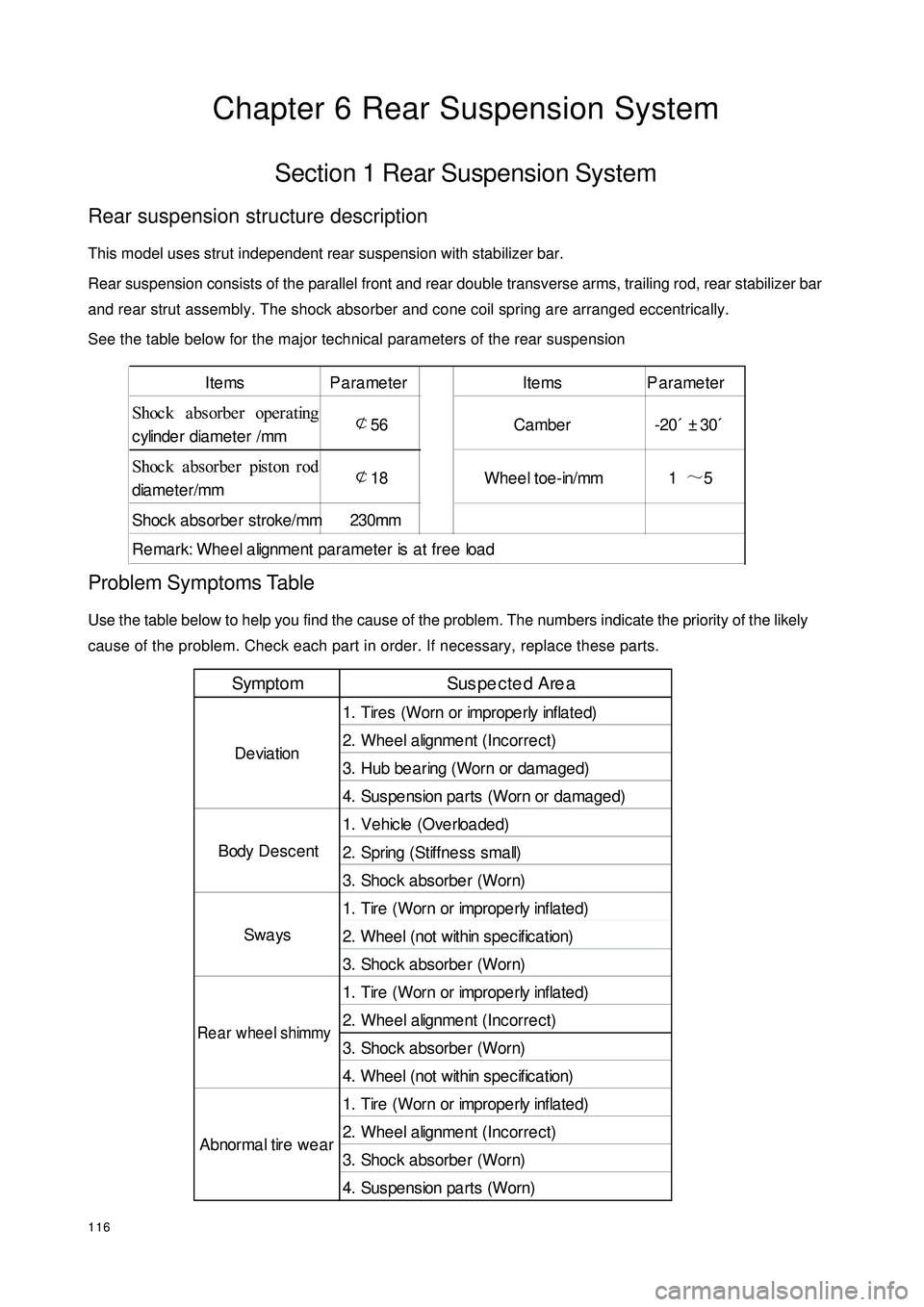
See the table below for the major technical parameters of the rear suspensionProblem Symptoms TableUse the table below to help you find the cause of the problem. The numbers indicate the priority of the likely
cause of the problem. Check each part in order. If necessary, replace these parts.Items Parameter Items Parameter
Shoc k a bsorbe r operating
cylinder diameter /mm¢
56 Cambe r -20´±30´
Shoc k a bsorbe r piston rod
diameter/mm¢
18 Wheel toe-in/mm 1~
5
Shoc k absorbe r stroke/mm 230mm
Remark: Wheel alignment parameter is at free loadSympto m Sus pe cte d Are a
1. Tires (Worn or imprope rly infla te d)
2. Wheel alignment (Incorrect)
3. Hub be a ring (Worn or da ma ge d)
4. Suspe nsion pa rts (Worn or da ma ge d)
1. Ve hic le (Ove rloa de d)
2. Spring (Stiffness small)
3. Shoc k a bsorbe r (Worn)
1. Tire (Worn or imprope rly inflate d)
2. W he e l ( not w it hin s pe c if ic a t ion)
3. Shoc k a bsorbe r (Worn)
1. Tire (Worn or imprope rly inflate d)
2. Wheel alignment (Incorrect)
3. Shoc k a bsorbe r (Worn)
4. W he e l ( not w it hin s pe c if ic a t ion)
1. Tire (Worn or imprope rly inflate d)
2. Wheel alignment (Incorrect)
3. Shoc k a bsorbe r (Worn)
4. Sus pe nsion pa rts (Worn) Abnormal tire wearDeviation
Body Desc ent
SwaysRear wheel shimmy
Page 124 of 392

117Section 2 Rear SuspensionComponents
LR Strut Assembly
LR ABS Sensor Wire Harness
LR Brake
LR Brake Pipe
Clip
Clip
RR Strut Assembly
Clip
RR ABS Sensor Wire Harness
RR Brake Hosex2
No. 2 Transverse Arm
Left Trailing Rod Assembly
Body
Body
Body Body
No. 1 Transverse Arm
No. 1 Rocker Arm
Clip
RR Brake Pipe
RR Brake Hose
RR Brake
Right Trailing Rod Assembly
Rear Stabilizer Bar Assembly
No. 2 Transverse Arm
Rear Stabilizer Bar Retainer
Rod Components
Page 125 of 392

118Section 3 Rear Wheel AlignmentInspection1. Inspect tire
Standard inflation pressure: 220 Kpa
2. Inspect rear wheel toe-in
If the rear wheel toe-in is not within the specification, adjust it via rear
wheel toe-in adjusting cam.
3. Inspect the camber
Notice: If the camber is not within the specification, check the suspension parts for damage/low
performance. Replace it if necessary.Toe-in C - D: 1~
5 mmC a m ber -20´± 30´FrontNo. 2 Transverse Arm Assembly Rear Wheel Toe-In
Adjusting PanelRear Wheel Toe-In
Adjusting PlateNo. 2 Transverse
Arm Assembly No. 1 Transverse
Arm Assembly No. 1 Transverse
Arm Assembly Rear Wheel Toe-In
Adjusting CamRear Wheel Toe-In
Adjusting CamBody Bottom Plate
Page 126 of 392
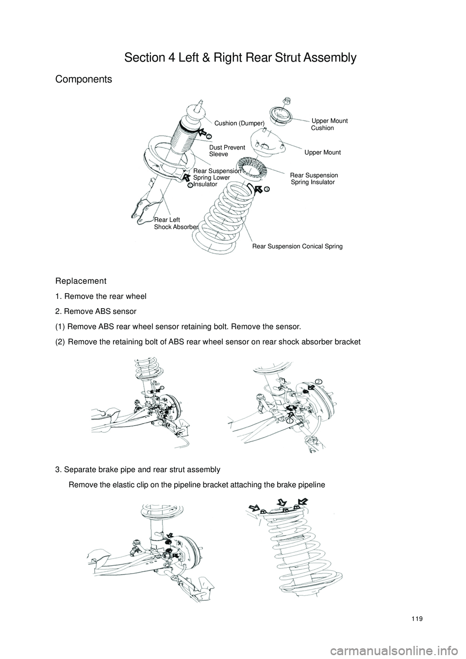
119Section 4 Left & Right Rear Strut AssemblyComponentsReplacement
1. Remove the rear wheel
2. Remove ABS sensor
(1) Remove ABS rear wheel sensor retaining bolt. Remove the sensor.
(2) Remove the retaining bolt of ABS rear wheel sensor on rear shock absorber bracket
3. Separate brake pipe and rear strut assembly
Remove the elastic clip on the pipeline bracket attaching the brake pipelineCushion (Dumper)Dust Prevent
SleeveRear Suspension
Spring Lower
InsulatorRear Left
Shock Absorber Upper Mount
CushionUpper MountRear Suspension
Spring Insulator
Rear Suspension Conical Spring
Page 127 of 392
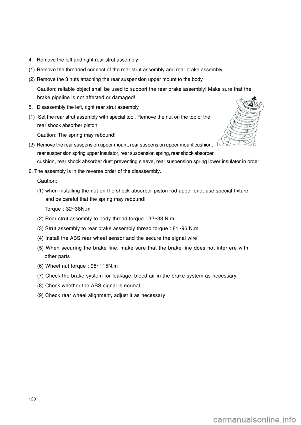
1204. Remove the left and right rear strut assembly
(1) Remove the threaded connect of the rear strut assembly and rear brake assembly
(2) Remove the 3 nuts attaching the rear suspension upper mount to the body
Caution: reliable object shall be used to support the rear brake assembly! Make sure that the
brake pipeline is not affected or damaged!
5. Disassembly the left, right rear strut assembly
(1) Set the rear strut assembly with special tool. Remove the nut on the top of the
rear shock absorber piston
Caution: The spring may rebound!
(2) Remove the rear suspension upper mount, rear suspension upper mount cushion,
rear suspension spring upper insulator, rear suspension spring, rear shock absorber
cushion, rear shock absorber dust preventing sleeve, rear suspension spring lower insulator in order
6. The assembly is in the reverse order of the disassembly.
Caution:
(1) when installing the nut on the shock absorber piston rod upper end, use special fixture
and be careful that the spring may rebound!
Torque : 32~38N.m
(2) Rear strut assembly to body thread torque : 32~38 N.m
(3) Strut assembly to rear brake assembly thread torque : 81~96 N.m
(4) Install the ABS rear wheel sensor and the secure the signal wire
(5) When securing the brake line, make sure that the brake line does not interfere with
other parts
(6) Wheel nut torque : 95~115N.m
(7) Check the brake system for leakage, bleed air in the brake system as necessary
(8) Check whether the ABS signal is normal
(9) Check rear wheel alignment, adjust it as necessary
Page 367 of 392

360(I) Front Sheet Metal, Cowl PartsThe main function of the front sheet metal and the cowl parts is forming an engine compartment to supply the
engine and accessories with a protective cover and to absorb the most energy when vehicle encounters
frontal impaction, protecting mud from being splashed by the front wheels, and meeting the requirements of
body design in appearance. It is mainly composed of front cross member assembly, LH/RH front mud guard
and front side member assembly, engine hood front support plate assembly, hood lock bracket assembly,
cowl assembly, cowl upper assembly.
1. Front Cross Member Assembly
The front cross member assembly is mainly composed of the front cross member welding sub-assembly,
front cross member bottom plate assembly, LH/RH side member end plate by welding them together, and its
dismantle diagram as shown in the Figure 5-2.
2. Lh/Rh Front Mudguard And Front Side Member Assembly
LH/RH front mud guard and front side member assembly is mainly composed of LH/RH front mudguards
and LH/RH side members by welding them together.
It is mainly used to mount some mounting brackets such as the engine LH/RH side suspension bracket, LH/
RH front suspension shock absorber bracket, etc. and to mount the LH/RH front fenders.
3. Engine Hood Front Support Plate Assembly
Engine hood front support plate is mainly composed of LH/RH headlamp mounting bracket assembly, hood
front support plate sub-assembly, and LH/RH front support plate reinforcement, by welding them together.
Engine hood front support plate assembly is used to mount radiator, engine hood lock, radiator grille, front
bumper, and headlamp.
4. Engine Hood Lock Bracket Assembly
Engine hood lock bracket assembly is used to mount the engine hood lock, also to strengthen the intensity and
rigidity of the front body by connecting the engine hood front support plate and front cross member.
5. Cowl Assembly
Cowl assembly is mainly composed of cowl inner and outer plate assembly and cowl lower cross member, by
welding them together.
Cowl assembly and front floor, LH/RH front mud guard (LH/RH front pillar), cowl upper baffle is welded
together, which forms a framework with great torsional strength. It generates great resistance to lateral
impact and rolled deformation.
Cowl inner and outer plate assembly is sandwich structure. 3mm of asphalt plate lies in the interlayer, which
is to cut off the noise and heat generated from the engine.