lock GEELY FC 2008 Owner's Manual
[x] Cancel search | Manufacturer: GEELY, Model Year: 2008, Model line: FC, Model: GEELY FC 2008Pages: 419, PDF Size: 13.87 MB
Page 50 of 419

34. Remove power steering pump assembly.
35. Remove sub frame together with side member.(a) Remove front engine mounting assembly and rear en-
gine mounting assembly from engine assembly.
(b) Remove sub frame assembly.36. Remove starter mounting components
[4G18-3708100].
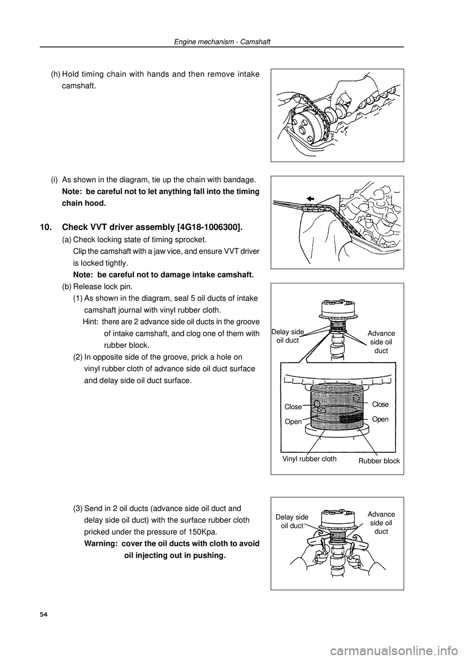
37. Remove transmission assembly.(a) Fix crankshaft with special tool, ant then remove 6 bolts.
(b) Remove transmission assembly.38. Remove clutch assembly [4G18-1601000]
and flywheel components [4G18-1005120J].(a) Fix crankshaft with special tool, ant remove clutch
assembly at first.
(b) Then remove flywheel components.39. Remove throttlesupporting plate [4G18-1008202].
40. Remove intake manifold assembly [4G18-
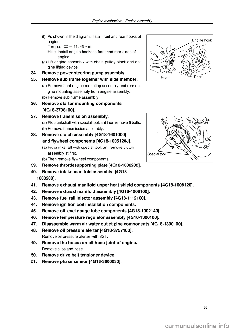
1008200].(f) As shown in the diagram, install front and rear hooks of
engine.
Torque: Hint: install engine hooks to front and rear sides of
engine.
(g) Lift engine assembly with chain pulley block and en-
gine lifting device.Engine mechanism - Engine assemblySpecial tool39 41. Remove exhaust manifold upper heat shield components [4G18-1008120].
42. Remove exhaust manifold assembly [4G18-1008100].
43. Remove fuel rail injector assembly [4G18-1112100].
44. Remove ignition coil installation components.
45. Remove oil level gauge tube components [4G18-1002140].
46. Remove temperature regulator assembly [4G18-1306100].
47. Disassemble warm air water outlet pipe components [4G18-1300100].
48. Remove oil pressure alerter [4G18-3757100].Remove oil pressure alerter with SST.49. Remove the hoses on all hose joint of engine.Remove clips and hose.50. Remove drive belt tensioner device.
51. Remove phase sensor [4G18-3600030].Engine hook
FrontRear
Page 52 of 419

Engine mechanism - Engine assembly64. Install temperature regulator assembly.(a) Check temperature regulator assembly o-ring.
(b) Install temperature regulator assembly as shown in the
diagram.
(c) Install engine water inlet pipe joint components.
Torque: 65. Install oil level gauge tube components.
66. Install ignition coil mounting components.Torque: m67. Install fuel rail injector assembly.(a) Install isolator on cylinder head.
(b) Install fuel rail injector assembly.
Torque: (c) Install fuel pipe retaining clip.68. Install exhaust manifold gasket and exhaust
manifold assembly.Torque: 69. Install exhaust manifold upper heat shield
components.Torque: 70. Install intake manifold assembly.Install new gasket and intake manifold assembly.
Torque: m71. Install throttle supporting plate.Torque: 72. Install flywheel components and clutch assembly.(a) Fix crankshaft with special tool.
(b) Clean bolts and bolt holes.
(c) Coat bolts with adhesive.
Adhesive: thread locking sealant 1234 (Kesaixin 1234).
(d) Install flywheel components.
As sequences shown in the diagram, tighten bolts at
several times.
Torque: 885Nm
(e) Install clutch assembly.Special
tool 41
Page 53 of 419

Engine mechanism - Engine assembly73. Install transmission assembly.(a) Install transmission assembly.
Torque: bolt A: Bolt B: Bolt C: (b) Install 6 bolts.
Torque: 74. nstall starter mounting components.Torque: bolt: Nut: 75. Install sub frame together with side member.Install front mounting assembly and rear mounting
assembly.
Torque: front: Rear: 76. Install power steering pump assembly.Torque: 77. Install engine assembly together with
transmission assembly.(a) Erect engine together with transmission assembly on
engine crane.
(b) Install engine assembly to vehicle.
(c) Temporarily install side member and 6 bolts.
(d) Install left engine mounting assembly.
Torque: (e) Install right engine mounting assembly.
(f) Insert special tool into location hole on right side of sub
frame and vehicle.
(g) Temporarily lock bolt A at first, and then lock bolt B.
(h) Insert special tool into location hole on left side of sub
frame and vehicle.
(i) Temporarily lock bolt A at first, and then lock bolt B.
(j) Insert special tool into location hole on right side of sub
frame and vehicle, and then tighten bolts up to speci-
fied torque.
Torque: bolt A: m
Bolt B: Special
tool
Special tool42
Page 56 of 419

Engine mechanism - Timing chain assemblyTiming chain assemblyReplacement1. Remove engine left bottom shield.
2. Remove engine right bottom shield.
3. Discharge coolant.
4. Remove engine plastic hood components.
5. Remove drive belt.
6. Remove power steering pump assembly.
7. Remove alternator assembly.
8. Uncouple engine wire harness.(a) Remove ignition coil joint, PS fuel pressure switch joint,
fuel line control joint and speed sensor joint.
(b) Remove bolts and nuts of fixed earth wire and put aside
engine wire harness.9. Remove ignition coil assembly.
10. Remove cylinder head cover components.(a) Remove fuel pipe retaining clip and 2 PCV hoses from
cylinder head cover.
(b) Remove 9 bolts, 2 seal washers, cylinder head cover
components and gasket.11. Remove right engine mounting assembly.(a) Remove PS oil pump reservoir and put it aside.
(b) Place wooden block between jack and engine, prop-
erly place the jack, and then remove right engine mount-
ing assembly.12. Turn crankshaft to cylinder 1 compression top
dead center position.
13. Remove damping pulley components
[4G18-1005110].Remove pulley bolts with special tool.
Remove damping pulley components with special tool.Special
tool
Special
tool45
Page 60 of 419

Engine mechanism - Timing chain assembly(b) Coat engine oil on the chain tensioner, and then install
it.
Torque: Note: when installing the chain temsioner, buckle
on the hook again if plunger has ejected.33. Install damping pulley.(a) Align the key groove on the damping pulley with the
key on the crankshaft, and slide damping pulley in.
(b) Install damping pulley bolts with special tool.
Torque: (c) Turn crankshaft counterclockwise to separate the hook
from lock pin on the plunger.
(d) Turn crankshaft clockwise, and check the chain ten-
sion rail is blocked by plunger.
Hint: if the plunger does not eject, press the chain ten-
sion rail toward chain tensioner with screwdriver
or fingers to separate the hook from lock pin and
make the plunger eject.Special
tool 49 Pushing intoSeparationHook
Pin
TurningPlunger
Pushing
intoTurning
Page 63 of 419

Engine mechanism - CamshaftCamshaftReplacement1. Remove engine hood.
2. Remove ignition coil assembly.
3. Remove cylinder head cover assembly.
4. Remove engine right bottom shield.
5. Turn crankshaft to cylinder 1 compression top dead
center position.(a) Turn damping pulley to align its groove with “o” mark on
timing chain hood.
(b) Check dot marks on camshaft timing sprocket and VVT
timing sprocket, and they should be in a line on timing chain
hood surface as shown in the diagram.
Hint: if not, turn crankshaft for one circle (360) again
and align the above marks.6. Remove drive belt.Slowly turn drive belt tensioner clockwise to loosen it.Then
remove drive belt and put back drive belt tensioner slowly and
gently.7. Remove right engine mounting assembly.(a) Remove PS oil pump reservoir and put it aside.
(b) Place wooden block between jack and engine, properly
place the jack, and then remove engine fixing bracket shock
absorber.8. Remove drive belt tensioner assembly.Hint: operate the jack up and down to remove bolts. 52Mark
Mark
Mark
Timing chain
hood surface
Groove
Page 65 of 419

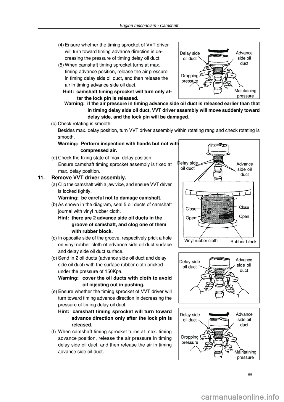
Engine mechanism - Camshaft(h) Hold timing chain with hands and then remove intake
camshaft.
(i) As shown in the diagram, tie up the chain with bandage.
Note: be careful not to let anything fall into the timing
chain hood.10. Check VVT driver assembly [4G18-1006300].(a) Check locking state of timing sprocket.
Clip the camshaft with a jaw vice, and ensure VVT driver
is locked tightly.
Note: be careful not to damage intake camshaft.
(b) Release lock pin.
(1) As shown in the diagram, seal 5 oil ducts of intake
camshaft journal with vinyl rubber cloth.
Hint: there are 2 advance side oil ducts in the groove
of intake camshaft, and clog one of them with
rubber block.
(2) In opposite side of the groove, prick a hole on
vinyl rubber cloth of advance side oil duct surface
and delay side oil duct surface.
(3) Send in 2 oil ducts (advance side oil duct and
delay side oil duct) with the surface rubber cloth
pricked under the pressure of 150Kpa.
Warning: cover the oil ducts with cloth to avoid
oil injecting out in pushing.54Delay side
oil ductAdvance
side oil
duct
Close
OpenClose
Open
Vinyl rubber cloth
Rubber blockDelay side
oil ductAdvance
side oil
duct
Page 66 of 419

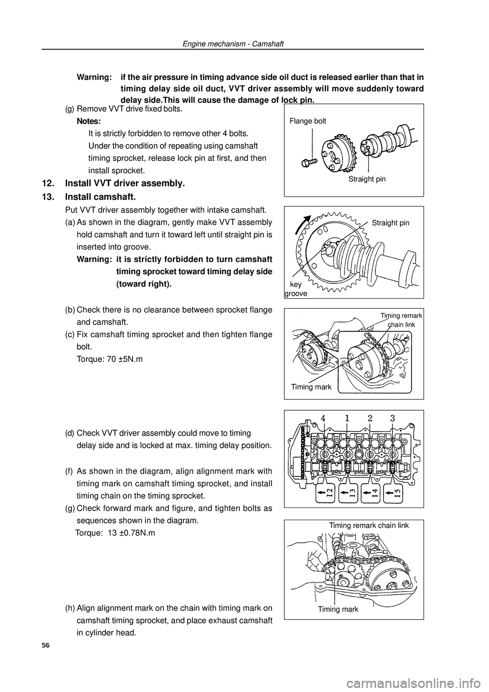
Engine mechanism - Camshaft(4) Ensure whether the timing sprocket of VVT driver
will turn toward timing advance direction in de-
creasing the pressure of timing delay oil duct.
(5) When camshaft timing sprocket turns at max.
timing advance position, release the air pressure
in timing delay side oil duct, and then release the
air in timing advance side oil duct.
Hint: camshaft timing sprocket will turn only af-
ter the lock pin is released.
(d) Check the fixing state of max. delay position.
Ensure camshaft timing sprocket assembly is fixed at
max. delay position.11. Remove VVT driver assembly.(a) Clip the camshaft with a jaw vice, and ensure VVT driver
is locked tightly.
Warning: be careful not to damage camshaft.
(b) As shown in the diagram, seal 5 oil ducts of camshaft
journal with vinyl rubber cloth.
Hint: there are 2 advance side oil ducts in the
groove of camshaft, and clog one of them
with rubber block.
(c) In opposite side of the groove, respectively prick a hole
on vinyl rubber cloth of advance side oil duct surface
and delay side oil duct surface.
(d) Send in 2 oil ducts (advance side oil duct and delay
side oil duct) with the surface rubber cloth pricked
under the pressure of 150Kpa.
Warning:cover the oil ducts with cloth to avoid
oil injecting out in pushing.
(e) Ensure whether the timing sprocket of VVT driver will
turn toward timing advance direction in decreasing the
pressure of timing delay oil duct.
Hint: camshaft timing sprocket will turn toward
advance direction only after the lock pin is
released.
(f) When camshaft timing sprocket turns at max. timing
advance position, release the air pressure in timing
delay side oil duct, and then release the air in timing
advance side oil duct. Warning: if the air pressure in timing advance side oil duct is released earlier than that
in timing delay side oil duct, VVT driver assembly will move suddenly toward
delay side, and the lock pin will be damaged.
(c) Check rotating is smooth.
Besides max. delay position, turn VVT driver assembly within rotating rang and check rotating is
smooth.
Warning: Perform inspection with hands but not with
compressed air.55Delay side
oil ductAdvance
side oil
duct
Close
OpenClose
Open
Vinyl rubber cloth
Rubber block
Delay side
oil ductAdvance
side oil
ductDropping
pressure
Maintaining
pressure Delay side
oil ductAdvance
side oil
duct
Dropping
pressure
Maintaining
pressure Delay side
oil ductAdvance
side oil
duct
Page 67 of 419

Engine mechanism - CamshaftWarning: if the air pressure in timing advance side oil duct is released earlier than that in
timing delay side oil duct, VVT driver assembly will move suddenly toward
delay side.This will cause the damage of lock pin.
(g) Remove VVT drive fixed bolts.
Notes:
It is strictly forbidden to remove other 4 bolts.
Under the condition of repeating using camshaft
timing sprocket, release lock pin at first, and then
install sprocket.12. Install VVT driver assembly.
13. Install camshaft.Put VVT driver assembly together with intake camshaft.
(a) As shown in the diagram, gently make VVT assembly
hold camshaft and turn it toward left until straight pin is
inserted into groove.
Warning: it is strictly forbidden to turn camshaft
timing sprocket toward timing delay side
(toward right).
(b) Check there is no clearance between sprocket flange
and camshaft.
(c) Fix camshaft timing sprocket and then tighten flange
bolt.
Torque: 70 ±5N.m
(d) Check VVT driver assembly could move to timing
delay side and is locked at max. timing delay position.
(f) As shown in the diagram, align alignment mark with
timing mark on camshaft timing sprocket, and install
timing chain on the timing sprocket.
(g) Check forward mark and figure, and tighten bolts as
sequences shown in the diagram.
Torque: 13 ±0.78N.m
(h) Align alignment mark on the chain with timing mark on
camshaft timing sprocket, and place exhaust camshaft
in cylinder head.Straight pin
key
grooveFlange bolt
Straight pin56Timing remark
chain linkTiming mark
Timing remark chain link
Timing mark
Page 69 of 419

Engine mechanism - Camshaft(n) Install chain tensioner components.
(1) Check o-ring is clean, and buckle on the hook as
shown in the diagram.
(2) Coat engine oil on the chain tensioner, and then
install it.
Torque: 9 ±1.8N.m
Note:when installing the chain temsioner,
buckle on the hook again if plunger has
ejected.
(3) Turn crankshaft counterclockwise to separate the
hook from lock pin on the plunger.
(4) Turn crankshaft clockwise, and check the sliding
parts are blocked by plunger.
Hint: if the plunger does not eject, press the ten-
sion rail toward chain tensioner with
screwdriver or fingers to separate the hook
from lock pin and make the plunger eject.Pushing into
Turning Plunger
Pushing into58Lifting
Hook Pressing
in
Pin
PinHook Sepa-
rate